weight SSANGYONG RODIUS 2005 Service Manual
[x] Cancel search | Manufacturer: SSANGYONG, Model Year: 2005, Model line: RODIUS, Model: SSANGYONG RODIUS 2005Pages: 502, PDF Size: 70.43 MB
Page 122 of 502

07-6
RODIUS 2005.07
2110-01
ENGINE COOLING SYSTEM
2. DESCRIPTION AND OPERATION
1) GENERAL DESCRIPTION
The cooling system maintains the engine temperature at an efficient level during all engine
operating conditions. When the engine is cold, the cooling system cools the engine slowly o
r
not at all. This slow cooling of the engine allows the engine to warm up quickly.
The cooling system includes a radiator and recovery subsystem, cooling fans, a thermostat and
housing, a water pump, and a water pump drive belt. The timing belt drives the water pump.
All components must function properly for the cooling system to operation. The water pump
draws the coolant from the radiator. The coolant then circulates through water jackets in the
engine block, the intake manifold, and the cylinder head. When the coolant reaches the
operating
temperature of the thermostat, the thermostat opens. The coolant then goes back to the
radiator where it cools.
This system directs some coolant through the hoses to the heat core. This provides for heating
and defrosting. The coolant reservoir is connected to the radiator to recover the coolant
displaced by expansion from the high temperatures. The coolant reservoir maintains the correct
coolant level.
The cooling system for this vehicle has no radiator cap or filler neck. The coolant is added to
the cooling system through the coolant reservoir.
2) RADIATOR
This vehicle has a lightweight tube-and-fin aluminum radiator. Plastic tanks are mounted on the
upper and the lower sides of the radiator core.
On vehicles equipped with automatic transaxles, the transaxle fluid cooler lines run through the
radiator tank. A radiator drain plug is on this radiator.
To drain the cooling system, open the drain plug.
Page 256 of 502

0-4
RODIUS 2005.07
4892-01
ABS SYSTEM
2. GENERAL INFORMATION
The aim of the ABS is to mmaintain steerability and driving stability and to take the burden off
the driver. If the stopping distance is shorter on some road surfaces (carriageway conditions),
this is a gift of physics and not a development aim.
ABS is a device which senses that one or more of the wheels are locking up during braking. It
monitors the rotational speeds of the wheels and reduces hydraulic pressure to any wheel it
senses locking up. It is controlled by both mechanical and electronic components. When you
apply the brakes, the ABS will regulate the flow of brake fluid being delivered to the brake
calipers. By the use of electronic computers, the brakes rapidly alternate (at a rate of 30 times
per second) from full pressure to full release.
1) DRIVING PHYSICS
To give you a better understanding of the tasks and functions of ABS, we will first look at the
physics principles.
(1) The Stopping Distance
The stopping distance depends on the vehicle weight and initial speed when braking starts.
This also applies for vehicle with ABS, where ABS always tries to set an optimum brake force
on each wheel. As great forces are exerted between the tires and the carriageway when
braking, even with ABS the wheels may scream and rubber is left on the road. With an
ABS
skid mark one may be able to clearly recognize the tire profile. The skid mark of an ABS vehicle
does not however leave any hint of the speed of the vehicle in the case of an accident, as it can
only be clearly drawn at the start of braking.
(2) Brake Force on a Wheel
The maximum possible brake force on a wheel depends on the wheel load and the adhesion
coefficient between tire and carriageway. With a low adhesion coefficient the brake force, which
can be obtained is very low. You are bound to know the result already from driving on winte
r
roads. With a high adhesion coefficient on a dry road, the brake force, which can be obtained,
is considerably higher. The brake force, which can be obtained, can be calculated from below
formula:
Page 257 of 502

0-5
ABS SYSTEM
RODIUS 2005.07
4892-01
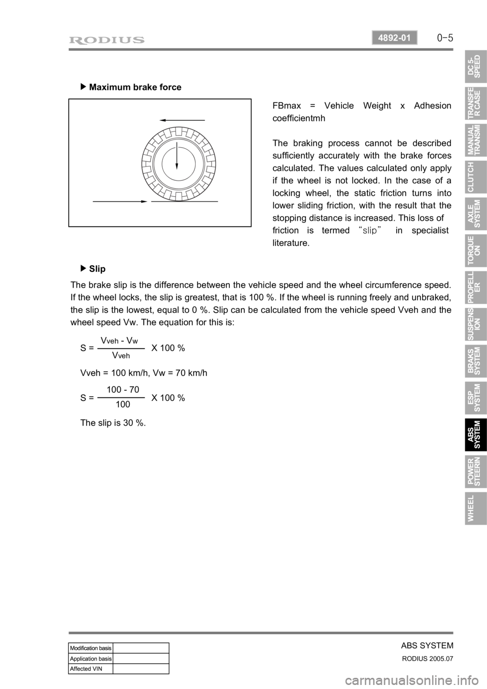
Maximum brake force ▶
FBmax = Vehicle Weight x Adhesion
coefficientmh
The braking process cannot be described
sufficiently accurately with the brake forces
calculated. The values calculated only apply
if the wheel is not locked. In the case of a
locking wheel, the static friction turns into
lower sliding friction, with the result that the
stopping distance is increased. This loss of
friction is termed “slip” in specialist
literature.
Slip ▶
The brake slip is the difference between the vehicle speed and the wheel circumference speed.
If the wheel locks, the slip is greatest, that is 100 %. If the wheel is running freely and unbraked,
the slip is the lowest, equal to 0 %. Slip can be calculated from the vehicle speed Vveh and the
wheel speed Vw. The equation for this is:
S = X 100 %
Vveh = 100 km/h, Vw = 70 km/h
S = X 100 %
The slip is 30 %.
Vveh - Vw
Vveh
100 - 70
100
Page 282 of 502

0-4
RODIUS 2005.07
4710-09
WHEEL
1. OVERVIEW OF WHEEL & TIRE
1) Tire And wheel Balancing
There are two types of the tire and wheel balancing: static and dynamic.
Static balance is the equaldistribution of weight around the wheel. assemblies that are statically
unbalanced cause a bouncing action called wheel tramp. This condition may eventually cause
uneven tire wear.
Dynamic balance is the equal distributio of weight on eeach side of the centerline so that when
the assembly spins there is no tendency for it to move frim side to side . Assemblies that are
dynamically unbalanced may cause wheel shimmy.
General Balance Precautions ▶
Remove all deposits of foreign material from the inside of the wheel.
Remove stones frim the gread in order to avoid operator injury during spin balancing -
Inspect the tire for any damage. Balance the tire according to the equipment manufacturer’s
recommendations.
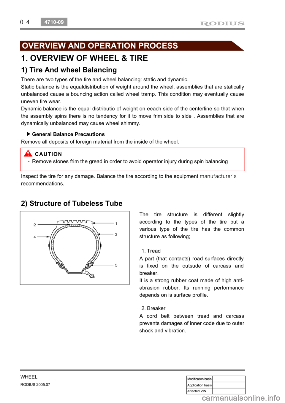
2) Structure of Tubeless Tube
The tire structure is different slightly
according to the types of the tire but a
various type of the tire has the common
structure as following;
Tread 1.
A part (that contacts) road surfaces directly
is fixed on the outsude of carcass and
breaker.
It is a strong rubber coat made of high anti-
abrasion rubber. Its running performance
depends on is surface profile.
A cord belt between tread and carcass
prevents damages of inner code due to oute
r
shock and vibration.Breaker 2.