ECU SSANGYONG RODIUS 2006 User Guide
[x] Cancel search | Manufacturer: SSANGYONG, Model Year: 2006, Model line: RODIUS, Model: SSANGYONG RODIUS 2006Pages: 444, PDF Size: 56.32 MB
Page 169 of 444

0-7
ELECTRIC GENERAL
RODIUS 2007.07
0000-00
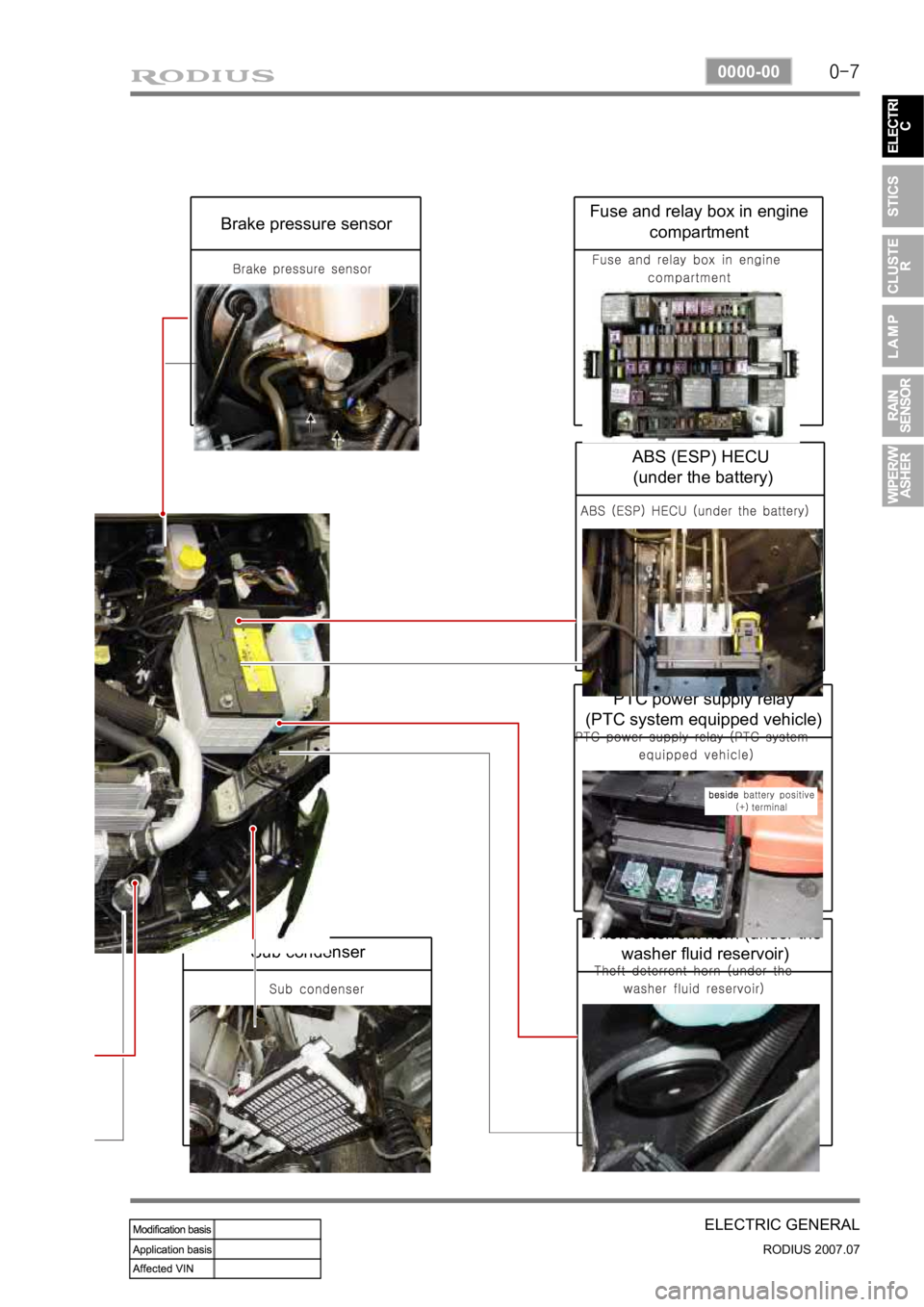
Sub condenser
Theft deterrent horn (under the washer fluid reservoir)
PTC power supply relay
(PTC system equipped vehicle)
ABS (ESP) HECU
(under the battery)
Fuse and relay box in engine compartmentBrake pressure sensor
Page 178 of 444

0-5
STICS
RODIUS 2007.07
8710-01
The STICS in this vehicle has similar functions with the one used in the new Rexton. Additional
function of diagnosing through SCAN-Tool has been added into new STICS.
The major difference in hardware-wise is that STICS receives vehicle collision signal from G-
sensor in the airbag module to activate automatic door unlock function when the vehicle
collided over 15 km/h of vehicle speed.
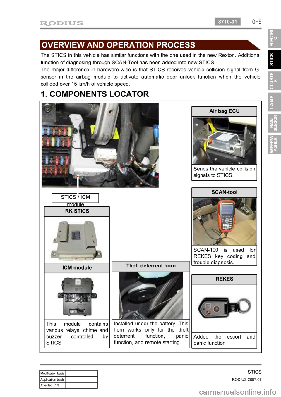
1. COMPONENTS LOCATOR
STICS / ICM module
Air bag ECU
Sends the vehicle collision
signals to STICS.
Theft deterrent horn
Installed under the battery. This
horn works only for the theft
deterrent function, panic
function, and remote starting.
SCAN-tool
SCAN-100 is used fo
r
REKES key coding and
trouble diagnosis.
REKES
Added the escort and
panic function
RK STICS
ICM module
This module contains
various relays, chime and
buzzer controlled by
STICS
Page 279 of 444

0-6
RODIUS 2007.07
3240-01
TORQUE ON DEMAND
When turning on the road with low friction rate ▶
During cornering on roads such as unpaved, snowy, icy and muddy, ground grab capacity is
increased by distributing required torque and, at the same time, comfortable steering operation
is maintained by controlling the ground grab capacity at high level.
Distribution ratio: 30 % for front wheels and 70 % for rear wheels.
When climbing or starting off on the road with low friction rate ▶
In order to secure the maximum ground grab capacity and driving force during climbing o
r
starting off on the roads such as unpaved, snowy and icy road, the system controls the driving
force to distribute properly in full 4WD mode.
Distribution ratio: 44 % for front wheels and 56 % for rear wheels.
Page 303 of 444

0-4
RODIUS 2007.07
4892-01
ESP SYSTEM
1. COMPONENTS AND LOCATIONS
2WD vehicle has the longitudinal sensor in the HECU.
1. HECU: (Hydraulic &
Engine conrol unit) 2. Pressure sensor 3. Wheel speed sensor
4. Sensor cluster:
(Yaw rate + lateral sensor + longitudinal sensor) 5. Steering wheel angle
sensor 6. ESP off switch (Electronic
Stability Program Switch) ESP Warning lamp
Page 305 of 444

0-6
RODIUS 2007.07
4892-01
ESP SYSTEM
3. ESP SYSTEM DESCRIPTION
1) Principle of ESP
ESP (Electronic Stability Program) recognizes critical driving conditions, such as panic
reactions in dangerous situations, and stabilizes the vehicle by wheel-individual braking and
engine control intervention with no need for actuating the brake. This system is developed to
help the driver avoid the danger of losing the control of the vehicle stability due to under-
steering or over-steering during cornering.
The yaw rate sensor, lateral sensor and longitudinal sensor in the sensor cluster and the
steering wheel angle sensor under the steering column detect the spin present at any wheels
during over-steering, under-steering or cornering. The ESP ECU controls against over-steering
or under-steering during cornering by controlling the vehicle stability using the input values from
the sensors and applying the brakes independently to the corresponding wheels.
The system also controls during cornering by detecting the moment right before the spin and
automatically limiting the engine output (coupled with the ASR system).
Understeering is when the steering wheel is
steered to a certain angle during driving and
the front tires slip toward the reverse
direction of the desired direction. Generally,
vehicles are designed to have unde
r
steering. The vehicle can return back to
inside of cornering line when the steering
wheel is steered toward the inside even
when the vehicle front is slipped outward.
As
the centrifugal force increases, the tires can
easily lose the traction and the vehicle tends
to slip outward when the curve angle gets
bigger and the speed increases. Under steering
ESP controls during under steering
The ESP system recognizes the directional
angle with the steering wheel angle senso
r
and senses the slipping route that occurs
reversely against the vehicle cornering
direction during understeering with the yaw
rate sensor and the lateral sensor. Then the
ESP system applies the brake at the rea
r
inner wheel to compensate the yaw moment
value.
In this way, the vehicle does not lose its
driving direction and the driver can steer the
vehicle as driver intends.
Page 309 of 444

0-10
RODIUS 2007.07
4892-01
ESP SYSTEM
4) HBA (Hydraulic Brake Assist System)
(1) Purpose
HBA (Hydraulic Brake Assist) system helps in an emergency braking situation when the driver
applies the brake fast, but not with sufficient pressure, which leads to dangerously long braking
distance. ECU recognizes the attempt at full braking and transmits the signal calling for full
brake pressure from the hydraulic booster. An inexperienced, elderly or physically weak drive
r
may suffer from the accident by not fully pressing the brake pedal when hard braking is
required
under emergency. The HBA System increases the braking force under urgent situations to
enhance the inputted braking force from the driver.
Based on the fact that some drivers depress the brake pedal too soft even under when hard
braking is necessary, the HECU system is a safety supplementary system that builds high
braking force during initial braking according to pressure value of the brake pressure senso
r
and the pressure changes of the pressure sensor intervals.
When the system is designed to apply high braking force when brake pedal is depressed softly
by an elderly or physically weak driver, the vehicle will make abrupt stopping under normal
braking situation due to high braking pressure at each wheels.
Page 310 of 444

0-11
ESP SYSTEM
RODIUS 2007.07
4892-01
(2) Operation
The brake pressure value and the changed value of the pressure sensor are the conditions in
which the HBA System operates. There are 2 pressure sensors under the master cylinder.
When the ESP ECU system determines that emergency braking is present, the pump operates,
the brake fluid in the master cylinder is sent to the pump and the braking pressure is delivered
to the wheels via the inlet valves.
If the drive depress the brake pedal slowly, the pressure change is not high. In this case, only
the conventional brake system with booster is activated.
Page 315 of 444

0-16
RODIUS 2007.07
4892-01
ESP SYSTEM
▶When applied ABS (decreased pressure)
The pressure decreases just before the wheel speed drops and the wheels. The inlet valve
closes and the outlet valve opens as in the ABS HECU and the oil is gathered at the low
pressure chamber while no additional oil is being supplied.
Then the pump operates to allow fast oil drainage.
Page 318 of 444

0-19
ESP SYSTEM
RODIUS 2007.07
4892-01
▶Hydraulic Diagram of HBA
The above figure shows one front and one rear wheel and the same hydraulic circuit forms as
in the ESP operation.
When HECU recognizes that it is an emergency and it is required for hard braking, depending
on the pressure value of the brake pressure sensor and pressure changes caused by the
pressure sensor timing, it operates the pump immediately to apply the brake pressure at the
wheels.
Then, the pressure in the pump increases until just before the corresponding wheel gets locked.
The motor still keeps rotating and the outlet valve and the separation valve are will stay closed.
When the wheel starts to lock, the HBA function cancels and switches to ABS operation.
Page 328 of 444

0-10
RODIUS 2007.07
4892-01
ABS SYSTEM
3. ON-VEHICLE SERVICE
(1) Electronic system service precautions
Take care to avoid electronic brake control module (HECU) circuit overloading. In testing for
opens or shorts, do not ground or apply voltage to any circuit unless instructed to do so by the
diagnostic procedure. Test circuits only with a high-impedance multi-meter. Never remove o
r
apply power to any control module with the ignition switch in the ON position. Always turn the
ignition to the OFF position before removing or connecting battery cables, fuses or connectors.
(2) General service precautions
Disconnect the HECU connector before performing any vehicle welding work using an electric
arc welder. Do not attempt to disassemble any component designated as nonserviceable. The
hydraulic modulator and the HECU can be seperated. (There is however no access to repai
r
the each components.)
(3) Bleeding system
Replacement modulators are shipped already filled and bled. In normal procedures requiring
removal of the modulator, such as to replace the HECU, air will not enter the modulator, and
normal bleeding will be all that is needed.
If air enters the hydraulic modulator, or if an unfilled modulator is installed, use the brake
bleeding program in the scan tool to bleed the modulator. Manual bleeding of the hydraulic
modulator is not possible.
1) Service Precautions
Brake Fluid may irritate eyes and skin. In case of contact, take the following actions:
Eye contact - rinse thoroughly with water.
Skin contact - wash with soap and water.
Ingestion - consult a physician immediately. -
-
-
To help avoid personal injury due to poor braking. DO NOT Tap into the vehicle’s
brake system to operate a trailer brake system.
When fasteners are removed, always reinstall them at the same location from which they
were removed. If a fastener needs to be replaced, use the correct part number fastener
for is not available, a fastener of equal size and strength (or stronger) may be used.
Fasteners that are not reused, and those requiring thread-locking compound will be
called out. The correct torque values must be used when installing fasteners that require
them. If the above procedures are not followed, parts or system damage could result.