wheel SSANGYONG RODIUS 2006 Workshop Manual
[x] Cancel search | Manufacturer: SSANGYONG, Model Year: 2006, Model line: RODIUS, Model: SSANGYONG RODIUS 2006Pages: 444, PDF Size: 56.32 MB
Page 337 of 444
0-19
ABS SYSTEM
RODIUS 2007.07
4892-01
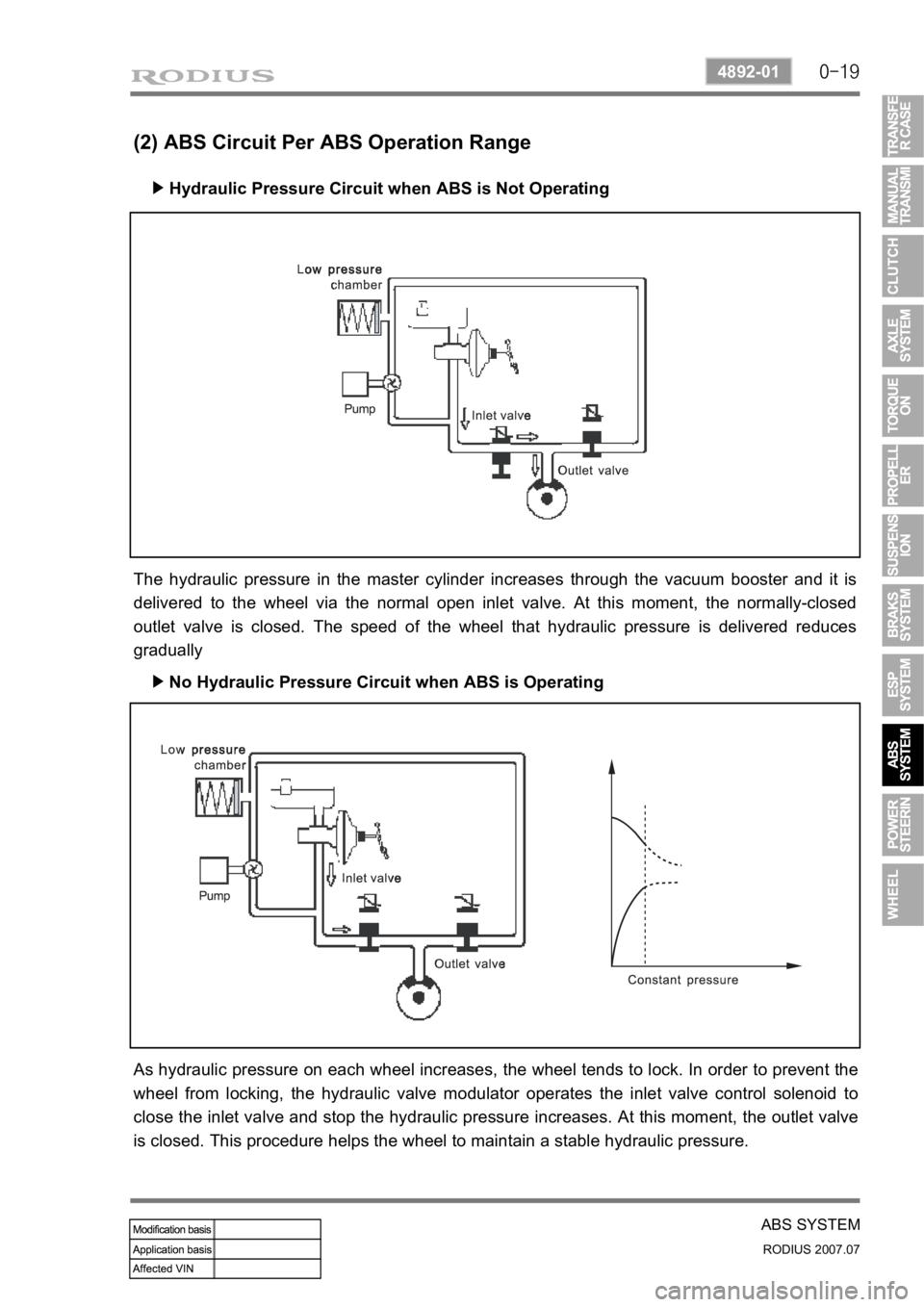
(2) ABS Circuit Per ABS Operation Range
Hydraulic Pressure Circuit when ABS is Not Operating ▶
No Hydraulic Pressure Circuit when ABS is Operating ▶
The hydraulic pressure in the master cylinder increases through the vacuum booster and it is
delivered to the wheel via the normal open inlet valve. At this moment, the normally-closed
outlet valve is closed. The speed of the wheel that hydraulic pressure is delivered reduces
gradually
As hydraulic pressure on each wheel increases, the wheel tends to lock. In order to prevent the
wheel from locking, the hydraulic valve modulator operates the inlet valve control solenoid to
close the inlet valve and stop the hydraulic pressure increases. At this moment, the outlet valve
is closed. This procedure helps the wheel to maintain a stable hydraulic pressure.
Page 338 of 444
0-20
RODIUS 2007.07
4892-01
ABS SYSTEM
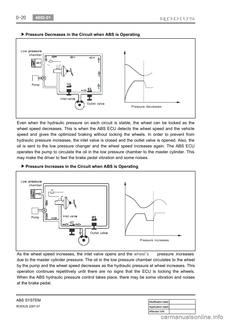
Pressure Decreases in the Circuit when ABS is Operating ▶
Pressure Increases in the Circuit when ABS is Operating ▶
Even when the hydraulic pressure on each circuit is stable, the wheel can be locked as the
wheel speed decreases. This is when the ABS ECU detects the wheel speed and the vehicle
speed and gives the optimized braking without locking the wheels. In order to prevent from
hydraulic pressure increases, the inlet valve is closed and the outlet valve is opened. Also, the
oil is sent to the low pressure changer and the wheel speed increases again. The ABS ECU
operates the pump to circulate the oil in the low pressure chamber to the master cylinder. This
may make the driver to feel the brake pedal vibration and some noises.
As the wheel speed increases, the inlet valve opens and the wheel’s pressure increases
due to the master cylinder pressure. The oil in the low pressure chamber circulates to the wheel
by the pump and the wheel speed decreases as the hydraulic pressure at wheel increases. This
operation continues repetitively until there are no signs that the ECU is locking the wheels.
When the ABS hydraulic pressure control takes place, there may be some vibration and noises
at the brake pedal.
Page 340 of 444
0-22
RODIUS 2007.07
4892-01
ABS SYSTEM
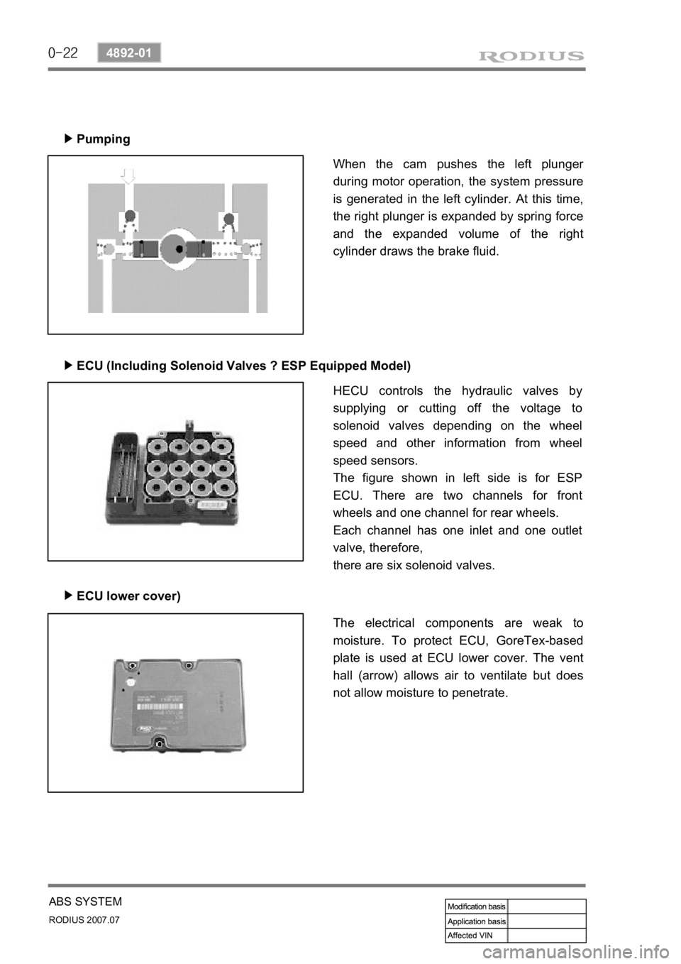
Pumping
▶
ECU (Including Solenoid Valves ? ESP Equipped Model)
▶
ECU lower cover)
▶
When the cam pushes the left plunger
during motor operation, the system pressure
is generated in the left cylinder. At this time,
the right plunger is expanded by spring force
and the expanded volume of the right
cylinder draws the brake fluid.
HECU controls the hydraulic valves by
supplying or cutting off the voltage to
solenoid valves depending on the wheel
speed and other information from wheel
speed sensors.
The figure shown in left side is for ESP
ECU. There are two channels for front
wheels and one channel for rear wheels.
Each channel has one inlet and one outlet
valve, therefore,
there are six solenoid valves.
The electrical components are weak to
moisture. To protect ECU, GoreTex-based
plate is used at ECU lower cover. The vent
hall (arrow) allows air to ventilate but does
not allow moisture to penetrate.
Page 343 of 444
0-5
POWER STEERING SYSTEM
RODIUS 2007.07
4610-00
4. OVERVIEW
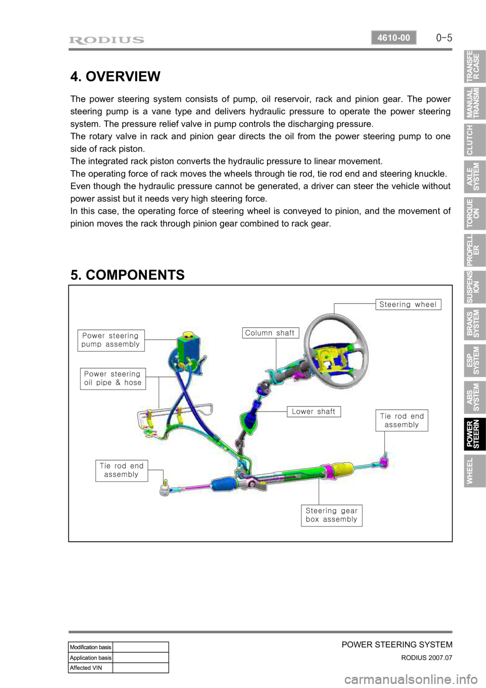
The power steering system consists of pump, oil reservoir, rack and pinion gear. The power
steering pump is a vane type and delivers hydraulic pressure to operate the power steering
system. The pressure relief valve in pump controls the discharging pressure.
The rotary valve in rack and pinion gear directs the oil from the power steering pump to one
side of rack piston.
The integrated rack piston converts the hydraulic pressure to linear movement.
The operating force of rack moves the wheels through tie rod, tie rod end and steering knuckle.
Even though the hydraulic pressure cannot be generated, a driver can steer the vehicle without
power assist but it needs very high steering force.
In this case, the operating force of steering wheel is conveyed to pinion, and the movement o
f
pinion moves the rack through pinion gear combined to rack gear.
5. COMPONENTS
Page 346 of 444
0-8
RODIUS 2007.07
4610-00
POWER STEERING SYSTEM
3. POWER STEERING PUMP
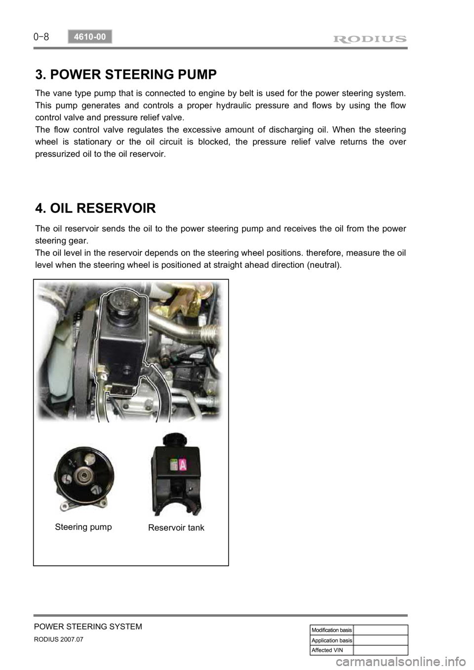
The vane type pump that is connected to engine by belt is used for the power steering system.
This pump generates and controls a proper hydraulic pressure and flows by using the flow
control valve and pressure relief valve.
The flow control valve regulates the excessive amount of discharging oil. When the steering
wheel is stationary or the oil circuit is blocked, the pressure relief valve returns the ove
r
pressurized oil to the oil reservoir.
4. OIL RESERVOIR
The oil reservoir sends the oil to the power steering pump and receives the oil from the power
steering gear.
The oil level in the reservoir depends on the steering wheel positions. therefore, measure the oil
level when the steering wheel is positioned at straight ahead direction (neutral).
Steering pump Reservoir tank
Page 347 of 444
0-3
WHEEL
RODIUS 2007.07
4710-09
4170-09WHEEL & TIRE
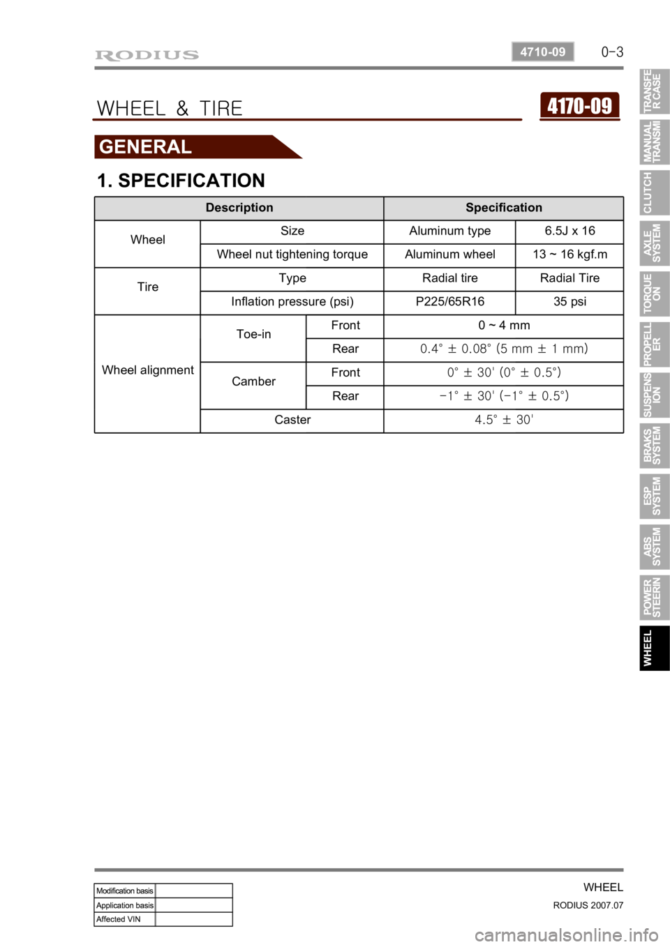
1. SPECIFICATION
Description Specification
WheelSize Aluminum type 6.5J x 16
Wheel nut tightening torque Aluminum wheel 13 ~ 16 kgf.m
TireType Radial tire Radial Tire
Inflation pressure (psi) P225/65R16 35 psi
Wheel alignmentToe-inFront 0 ~ 4 mm
Rear0.4° ± 0.08° (5 mm ± 1 mm)
CamberFront0° ± 30' (0° ± 0.5°)
Rear-1° ± 30' (-1° ± 0.5°)
Caster4.5° ± 30'
Page 348 of 444
0-4
RODIUS 2007.07
4710-09
WHEEL
1. OVERVIEW OF WHEEL & TIRE
1) Tire And wheel Balancing
There are two types of the tire and wheel balancing: static and dynamic.
Static balance is the equaldistribution of weight around the wheel. assemblies that are statically
unbalanced cause a bouncing action called wheel tramp. This condition may eventually cause
uneven tire wear.
Dynamic balance is the equal distributio of weight on eeach side of the centerline so that when
the assembly spins there is no tendency for it to move frim side to side . Assemblies that are
dynamically unbalanced may cause wheel shimmy.
General Balance Precautions ▶
Remove all deposits of foreign material from the inside of the wheel.
Remove stones frim the gread in order to avoid operator injury during spin balancing -
Inspect the tire for any damage. Balance the tire according to the equipment
manufacturer’s recommendations.
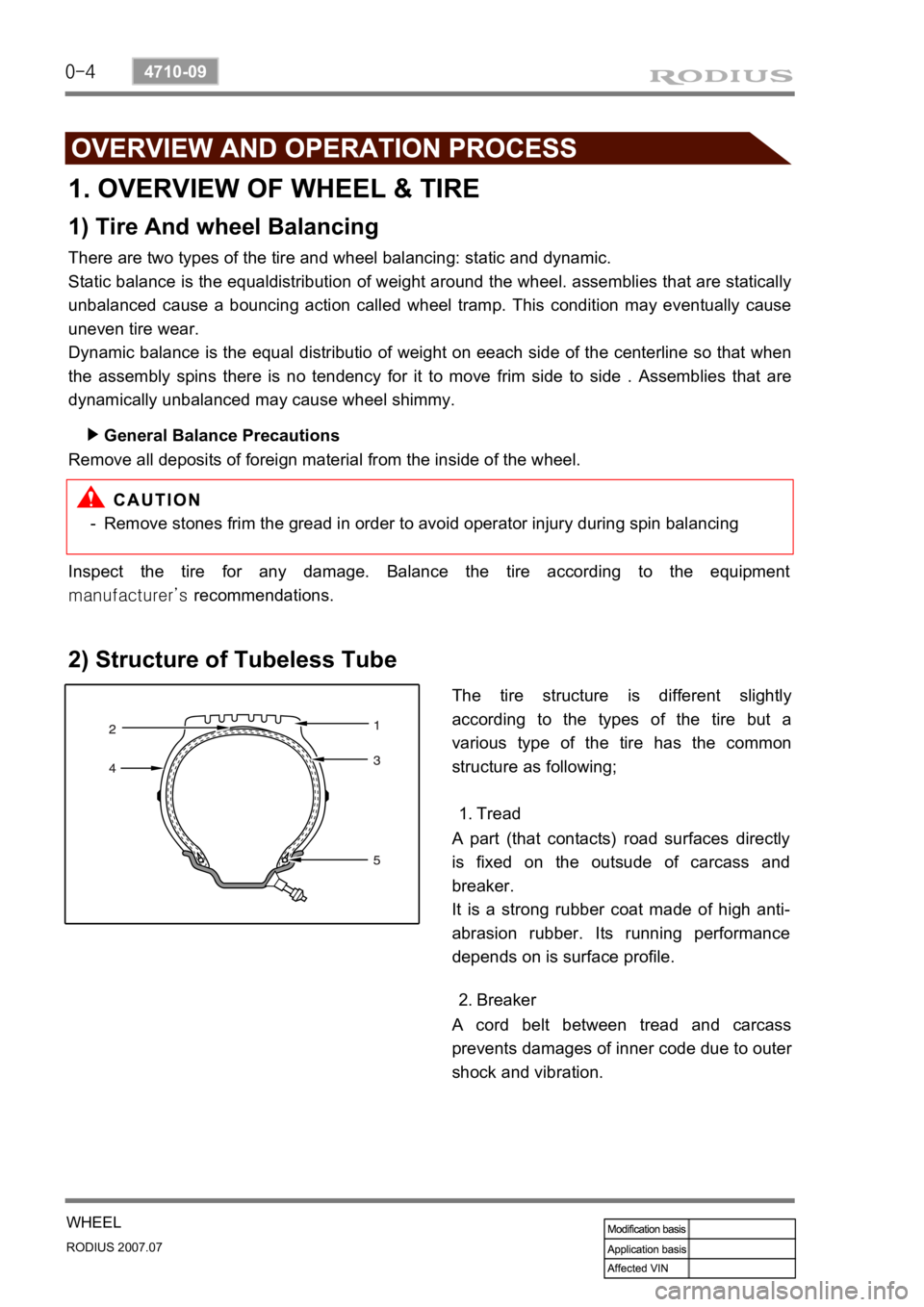
2) Structure of Tubeless Tube
The tire structure is different slightly
according to the types of the tire but a
various type of the tire has the common
structure as following;
Tread 1.
A part (that contacts) road surfaces directly
is fixed on the outsude of carcass and
breaker.
It is a strong rubber coat made of high anti-
abrasion rubber. Its running performance
depends on is surface profile.
A cord belt between tread and carcass
prevents damages of inner code due to oute
r
shock and vibration.Breaker 2.
Page 349 of 444
0-5
WHEEL
RODIUS 2007.07
4710-09
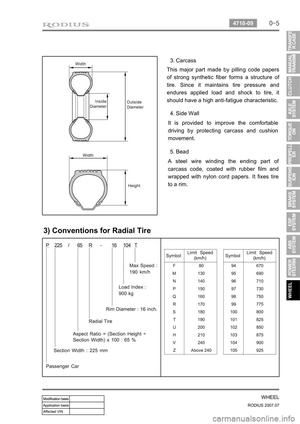
Carcass 3.
This major part made by pilling code papers
of strong synthetic fiber forms a structure o
f
tire. Since it maintains tire pressure and
endures applied load and shock to tire, it
should have a high anti-fatigue characteristic.
Side Wall 4.
It is provided to improve the comfortable
driving by protecting carcass and cushion
movement.
Bead 5.
A steel wire winding the ending part o
f
carcass code, coated with rubber film and
wrapped with nylon cord papers. It fixes tire
to a rim.
3) Conventions for Radial Tire
Page 350 of 444
0-6
RODIUS 2007.07
4710-09
WHEEL
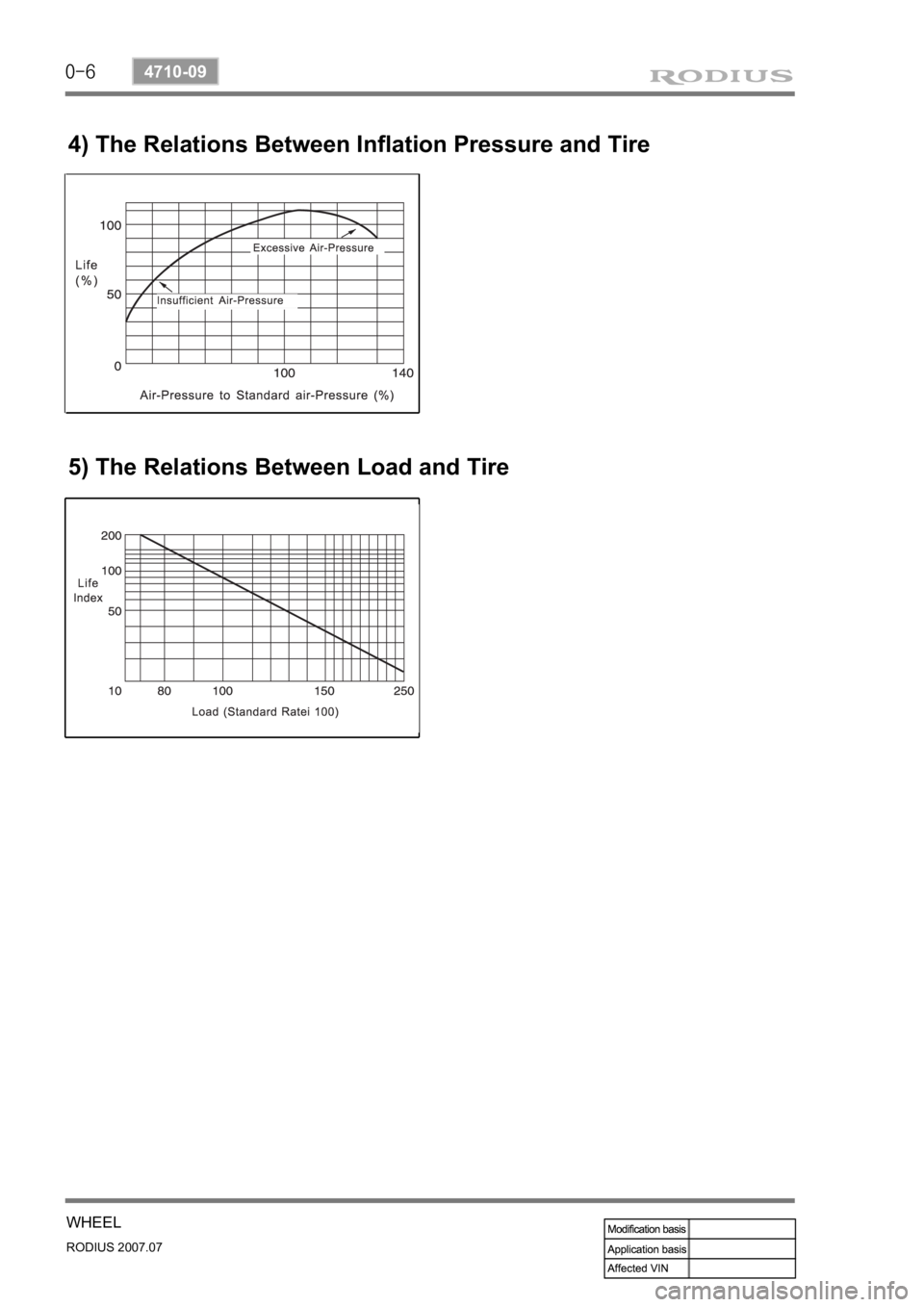
4) The Relations Between Inflation Pressure and Tire
5) The Relations Between Load and Tire
Page 351 of 444
0-7
WHEEL
RODIUS 2007.07
4710-09
2. TIRE’S ABNORMAL PHENOMENA
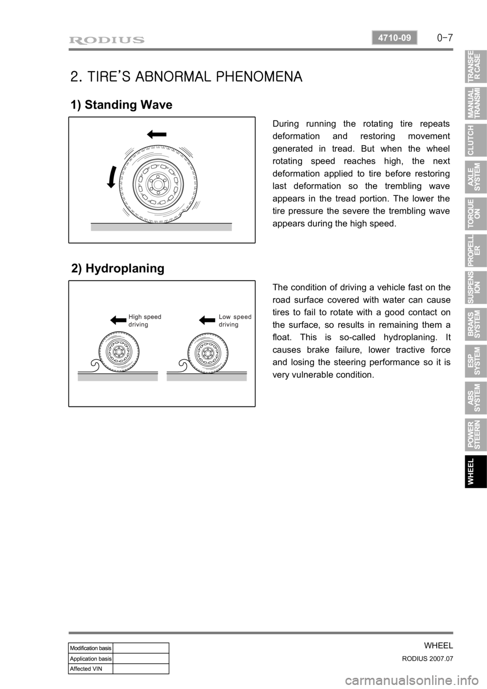
1) Standing Wave
2) Hydroplaning
During running the rotating tire repeats
deformation and restoring movement
generated in tread. But when the wheel
rotating speed reaches high, the next
deformation applied to tire before restoring
last deformation so the trembling wave
appears in the tread portion. The lower the
tire pressure the severe the trembling wave
appears during the high speed.
The condition of driving a vehicle fast on the
road surface covered with water can cause
tires to fail to rotate with a good contact on
the surface, so results in remaining them a
float. This is so-called hydroplaning. It
causes brake failure, lower tractive force
and losing the steering performance so it is
very vulnerable condition.