wheel SSANGYONG RODIUS 2006 User Guide
[x] Cancel search | Manufacturer: SSANGYONG, Model Year: 2006, Model line: RODIUS, Model: SSANGYONG RODIUS 2006Pages: 444, PDF Size: 56.32 MB
Page 278 of 444

0-5
TORQUE ON DEMAND
RODIUS 2007.07
3240-01
2. GENERAL DESCRIPTION
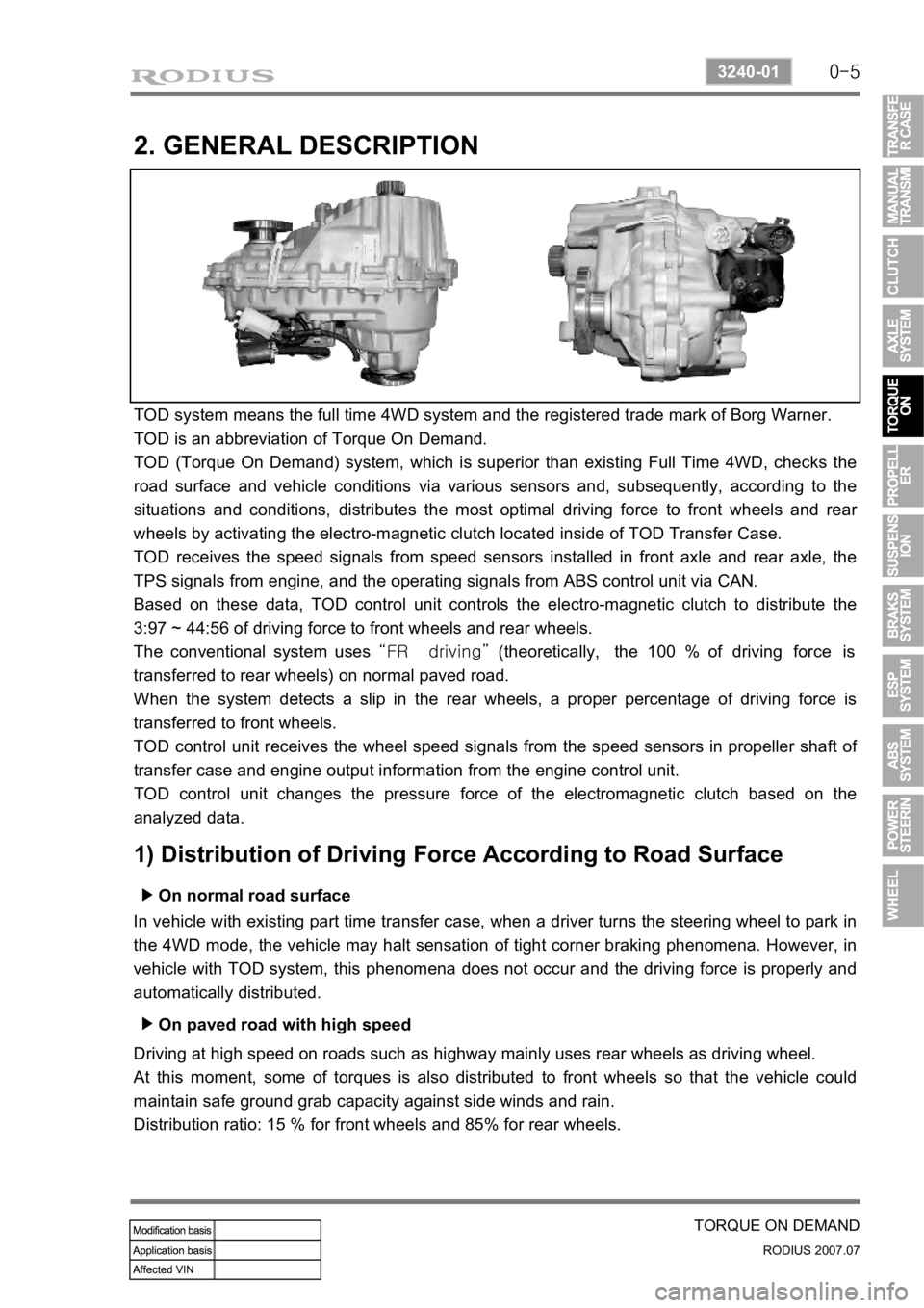
TOD system means the full time 4WD system and the registered trade mark of Borg Warner.
TOD is an abbreviation of Torque On Demand.
TOD (Torque On Demand) system, which is superior than existing Full Time 4WD, checks the
road surface and vehicle conditions via various sensors and, subsequently, according to the
situations and conditions, distributes the most optimal driving force to front wheels and rea
r
wheels by activating the electro-magnetic clutch located inside of TOD Transfer Case.
TOD receives the speed signals from speed sensors installed in front axle and rear axle, the
TPS signals from engine, and the operating signals from ABS control unit via CAN.
Based on these data, TOD control unit controls the electro-magnetic clutch to distribute the
3:97 ~ 44:56 of driving force to front wheels and rear wheels.
The conventional system uses “FR driving” (theoretically, the 100 % of driving force is
transferred to rear wheels) on normal paved road.
When the system detects a slip in the rear wheels, a proper percentage of driving force is
transferred to front wheels.
TOD control unit receives the wheel speed signals from the speed sensors in propeller shaft o
f
transfer case and engine output information from the engine control unit.
TOD control unit changes the pressure force of the electromagnetic clutch based on the
analyzed data.
1) Distribution of Driving Force According to Road Surface
On normal road surface ▶
In vehicle with existing part time transfer case, when a driver turns the steering wheel to park in
the 4WD mode, the vehicle may halt sensation of tight corner braking phenomena. However, in
vehicle with TOD system, this phenomena does not occur and the driving force is properly and
automatically distributed.
On paved road with high speed ▶
Driving at high speed on roads such as highway mainly uses rear wheels as driving wheel.
At this moment, some of torques is also distributed to front wheels so that the vehicle could
maintain safe ground grab capacity against side winds and rain.
Distribution ratio: 15 % for front wheels and 85% for rear wheels.
Page 279 of 444

0-6
RODIUS 2007.07
3240-01
TORQUE ON DEMAND
When turning on the road with low friction rate ▶
During cornering on roads such as unpaved, snowy, icy and muddy, ground grab capacity is
increased by distributing required torque and, at the same time, comfortable steering operation
is maintained by controlling the ground grab capacity at high level.
Distribution ratio: 30 % for front wheels and 70 % for rear wheels.
When climbing or starting off on the road with low friction rate ▶
In order to secure the maximum ground grab capacity and driving force during climbing o
r
starting off on the roads such as unpaved, snowy and icy road, the system controls the driving
force to distribute properly in full 4WD mode.
Distribution ratio: 44 % for front wheels and 56 % for rear wheels.
Page 280 of 444

0-7
TORQUE ON DEMAND
RODIUS 2007.07
3240-01
2) Transfer Case
(1) Planetary gear set
Planetary Gear set consists of sun gear, ring gear and carrier. It is engaged with the gear in
“HIGH-LOW” collar to increase the driving force by reducing vehicle speed.
Sun gear is connected to input shaft and ring gear is fixed into the transfer case.
Splined rear output shaft is able to slide on the “HIGH - LOW” collar.
The inside and outside ends of “HIGH - LOW” collar have machined gear. The input
shaft transmits the power to driving wheels by engaging with sun gear and carrier gear.
If the 4WD switch is at “4WD HIGH”, the TOD control unit operates the shift motor to
engage “HIGH - LOW” collar directly with input shaft for transmitting the driving force
to front and rear propeller shafts.
When a driver selects “4WD LOW”, the TOD control unit controls the electro-
magnetic clutch and operates the shift motor to engage “HIGH - LOW” collar with
carrier.
The power from transmission is increased up to 2.48:1 by reduction ratio from planetary
gear, and then is sent to front and rear propeller shafts. null
(2) Ball type slant cam and clutch
disc pack
If the speed sensors installed on front and
rear propeller shafts detect the slips at front
and rear wheels, and these slips exceed
the specified range, TOD control unit
controls electromagnetic clutch to transmit
driving force to front wheels.
At this time, ball slant cam is moved to
compress multi-disc located in clutch disc to
transmit driving force to front wheels.
Page 281 of 444

0-8
RODIUS 2007.07
3240-01
TORQUE ON DEMAND
(3) Electro Magnetic Clutch (EMC)
EMC consists of coil and housing. TOD control unit controls EMC by controlling duty cycle
according to the road and driving conditions. These controls use the continuity time and amount
of electric current to determine the torque to be transmitted to front wheels.
Basic controls in EMC ▶
Page 286 of 444

0-13
TORQUE ON DEMAND
RODIUS 2007.07
3240-01
2) 4WD Operation Overview
To make the mode shift easier, stop the vehicle, depress the brake pedal, select the mode
switch, and move the selector lever with the sequence of [N-P-N].
3) Mode Switch
Selection Mode ▶
The TOD system has 2 selectable mode, 4H and 4L.
4H is the normal operating mode when drive of which gear ratio is 1:1 and 4L mode distributes
power to front and rear wheels 50:50 of which gear ratio is 2.48:1.
4L Mode ▶
When selecting 4L mode, EMC is locked to apply maximum torque into front and rear propelle
r
shafts (when the wheel speed is more than 87Hz).
Shift motor rotates also 4L position by rotation of cam thus propeller shaft torque changes from
1:1 to 2.48:1 by planetary gear set.
Releasing the 4L Mode ▶
When selecting 4H mode, 4L drive mode is
released and 4H mode is resumed.
“4H” switch: Self-return type
“4L” switch: Push lock type ·
·
Page 299 of 444

0-6
RODIUS 2007.07
4830-01
BRAKS SYSTEM
2. BRAKE SYSTEM OPERATION PROCESS
1) Brake System
Even though a driver cuts off the power, while driving, the vehicle continues to move due to the
law of inertia. Therefore, a braking device is needed to stop the vehicle. The brake system
normally uses the frictional discs that converts the kinetic energy to the thermal energy by
frictional operation.
The brake system consists of the brake disc (front wheel), brake disc or drum (rear wheel),
parking brake (mechanical type), master cylinder, booster, pedal and supply lines (pipes and
hoses).
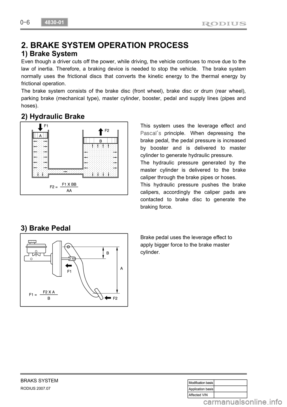
2) Hydraulic Brake
This system uses the leverage effect and
Pascal’s principle. When depressing the
brake pedal, the pedal pressure is increased
by booster and is delivered to maste
r
cylinder to generate hydraulic pressure.
The hydraulic pressure generated by the
master cylinder is delivered to the brake
caliper through the brake pipes or hoses.
This hydraulic pressure pushes the brake
calipers, accordingly the caliper pads are
contacted to brake disc to generate the
braking force.
3) Brake Pedal
Brake pedal uses the leverage effect to
apply bigger force to the brake master
cylinder.
Page 300 of 444

0-7
BRAKS SYSTEM
RODIUS 2007.07
4830-01
4) Master Cylinder
The brake master cylinder is designed to
convert the force from the brake maste
r
cylinder to the high hydraulic pressure. The
brake system uses the tandem type master
cylinder with in-line 2 pistons.
The in-line 2 pistons generate the hydraulic
pressure. The piston cup on the piston keeps
the sealing conditions in cylinder and
prevents the oil leaks. The hydraulic
pressure generated by the primary piston is
delivered to the front wheels, and the
hydraulic pressure generated by the
secondary piston is delivered to the rea
r
wheels.
5) Brake Booster
The brake booster is a power assist device for brake system. It relieves the pedal depressing
force by using the pressure difference between the vacuum pressure generated by vacuum
pump in intake manifold and the atmospheric pressure.
▶Pressure distribution at working
When depressing the brake pedal, the push
rod (1) in booster pushes the poppet (2) and
valve plunger (3). The poppet (2) pushes the
power piston seat (5) resulting in closing the
vacuum valve (9). The chamber (A) and (B)
in power cylinder are isolated and the valve
plunger (3) is separated from the poppet (2).
And then the air valve (6) opens and ai
r
flows into the chamber (B) through filter.
Then, the power piston (5) pushes the
master cylinder push rod (7) to assist the
brake operation.
▶Pressure distribution after working
When releasing the brake pedal, the valve
plunger (3) returns back to the original
position by return spring (4) and the air valve
(6) closes. At this time, the vacuum valve (9)
opens and the pressure difference between
chamber (A) and (B) in power cylinder is
eliminated. Accordingly, the power piston (5)
returns back to original position by the
reaction of master cylinder (10) and the
diaphragm return spring (8).
Page 302 of 444

0-3
ESP SYSTEM
RODIUS 2007.07
4892-01
8510-56ABS/ESP System
1. SPECCIFICATIONS OF ESP SYSTEM
1) Specifications Of Pressure Sensor
2) Specifications Of Sensor Cluster
(sensor cluster: yaw rate sensor + lateral acceleration sensor + Longitudinal acceleration sensor)
3) Specifications Of Wheel Speed Sensor
4) Specifications Of Steering Wheel Angle sensor
Page 303 of 444

0-4
RODIUS 2007.07
4892-01
ESP SYSTEM
1. COMPONENTS AND LOCATIONS
2WD vehicle has the longitudinal sensor in the HECU.
1. HECU: (Hydraulic &
Engine conrol unit) 2. Pressure sensor 3. Wheel speed sensor
4. Sensor cluster:
(Yaw rate + lateral sensor + longitudinal sensor) 5. Steering wheel angle
sensor 6. ESP off switch (Electronic
Stability Program Switch) ESP Warning lamp
Page 305 of 444

0-6
RODIUS 2007.07
4892-01
ESP SYSTEM
3. ESP SYSTEM DESCRIPTION
1) Principle of ESP
ESP (Electronic Stability Program) recognizes critical driving conditions, such as panic
reactions in dangerous situations, and stabilizes the vehicle by wheel-individual braking and
engine control intervention with no need for actuating the brake. This system is developed to
help the driver avoid the danger of losing the control of the vehicle stability due to under-
steering or over-steering during cornering.
The yaw rate sensor, lateral sensor and longitudinal sensor in the sensor cluster and the
steering wheel angle sensor under the steering column detect the spin present at any wheels
during over-steering, under-steering or cornering. The ESP ECU controls against over-steering
or under-steering during cornering by controlling the vehicle stability using the input values from
the sensors and applying the brakes independently to the corresponding wheels.
The system also controls during cornering by detecting the moment right before the spin and
automatically limiting the engine output (coupled with the ASR system).
Understeering is when the steering wheel is
steered to a certain angle during driving and
the front tires slip toward the reverse
direction of the desired direction. Generally,
vehicles are designed to have unde
r
steering. The vehicle can return back to
inside of cornering line when the steering
wheel is steered toward the inside even
when the vehicle front is slipped outward.
As
the centrifugal force increases, the tires can
easily lose the traction and the vehicle tends
to slip outward when the curve angle gets
bigger and the speed increases. Under steering
ESP controls during under steering
The ESP system recognizes the directional
angle with the steering wheel angle senso
r
and senses the slipping route that occurs
reversely against the vehicle cornering
direction during understeering with the yaw
rate sensor and the lateral sensor. Then the
ESP system applies the brake at the rea
r
inner wheel to compensate the yaw moment
value.
In this way, the vehicle does not lose its
driving direction and the driver can steer the
vehicle as driver intends.