ignition SSANGYONG RODIUS 2006 Service Manual
[x] Cancel search | Manufacturer: SSANGYONG, Model Year: 2006, Model line: RODIUS, Model: SSANGYONG RODIUS 2006Pages: 444, PDF Size: 56.32 MB
Page 4 of 444
0-4undefined
0000-00
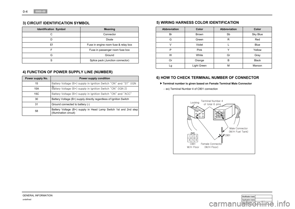
GENERAL INFORMATION3) CIRCUIT IDENTIFICATION SYMBOL
Identification Symbol Meaning
C Connector
D Diode
Ef Fuse in engine room fuse & relay box
F Fuse in passenger room fuse box
G Ground
S Splice pack (Junction connector)
5) WIRING HARNESS COLOR IDENTIFICATION
Abbreviation Color Abbreviation Color
Br Brown Sb Sky Blue
G Green R Red
V Violet L Blue
P Pink Y Yellow
W White Gr Gray
Or Orange B Black
Lg Light Green M Maroon
6) HOW TO CHECK TERMINAL NUMBER OF CONNECTOR
Terminal number is given based on Female Terminal Male Connector ▶
ex) Terminal Number 4 of C901 connection -
Power supply No. Power supply condition
15<00690088009b009b008c009900a00047007d00960093009b0088008e008c0047004f0069005200500047009a009c00970097009300a000470090009500470070008e00950090009b0090009600950047007a009e0090009b008a008f004702c80076007502
c9004700880095008b004702c8007a007b02c90047004f0070>GN
1)
15A<00690088009b009b008c009900a00047007d00960093009b0088008e008c0047004f0069005200500047009a009c00970097009300a000470090009500470070008e00950090009b0090009600950047007a009e0090009b008a008f004702c80076007502
c90047004f0070006e0075004700590050>
15C<00690088009b009b008c009900a00047007d00960093009b0088008e008c0047004f0069005200500047009a009c00970097009300a000470090009500470070008e00950090009b0090009600950047007a009e0090009b008a008f004702c80076007502
c9004700880095008b004702c80068006a006a02c9>
30 Battery Voltage (B+) supply directly regardless of Ignition Switch
31 Ground connected to battery (-)
58Battery Voltage (B+) supply in Head Lamp Switch 1st and 2nd step
(Illumination circuit)4) FUNCTION OF POWER SUPPLY LINE (NUMBER)
Page 67 of 444
01-7
ENGINE INFORMATION
RODIUS 2007.07
0000-00
2. DESCRIPTION AND OPERATION
1) Cleanliness And Care
An automobile engine is a combination of many machined, honed, polished and lapped
surfaces with tolerances that are measured in the ten-thousanths of an inch. When any internal
engine parts are serviced, care and cleanliness are important. A liberal coating of enigne oil
should be applied to friction areas during assembly, to protect and lubricate the surfaces on
initial operation.
Proper cleaning and protection of machined surfaces and friction areas is part of the repai
r
procedure. This is considered standard shop practice even if not specifically stated.
Whenever valve train components are removed for service, they should be kept in order.
They should be installed in the same locations, and with the same mating surfaces, as when
they were removed. Battery cables should be disconnected before any major work is performed
on the engine. Failure to disconnect cables may result in damage to wire harness or othe
r
electrical parts.
2) On-Engine Service
Disconnect the negative battery cable before removing or installing any electrical unit, or
when a tool or equipment could easily come in contact with exposed electrical terminals.
Disconnecting this cable will help prevent personal injury and damage to the vehicle.
The ignition must also be in LOCK unless otherwise noted.
Notice Any time the air cleaner is removed, the intake opening -
Any time the air cleaner is removed, the intake opening should be covered. This will
protect against accidental entrance of foreign material, which could follow the intake
passage into the cylinder and cause extensive damage when the engine is started.g -
Page 90 of 444
08-5
ENGINE ELECTRIC DEVICES
RODIUS 2007.07
0000-00
1. CHARGING SYSTEM OPERATION
Alternators use a new type of regulator that incorpo-rates a diode trio. A Delta stator, a rectifier
bridge, and a rotor with slip rings and brushes are electrically similar to earlier alternators.
A conventional pulley and fan are used. There is no test hole.
1) CHARGING TIME REQUIRED
The time required to charge a battery will vary depending upon the following factors:
▶ Size of Battery
A Completely discharged large heavy-duty battery required more than twice the
recharging time as a completely discharged small passenger car battery. -
▶ Temperature
A longer time will be needed to charge any battery at -18°C (0°F) than at 27°C
(80°F). When a fast charger is connected to a cold battery, the current accepted
by the battery will be very low at first. The battery will accept a higher current rate as the
battery warms. -
▶ Charger Capacity
A charger which can supply only 5 amperes will require a much longer charging period
than a charger that can supply 30 amperes or more. -
▶ State-of-Charge
A completely discharged battery requires more than twice as much charge as a onehal
f
charged battery. Because the electrolyte is nearly pure water and a poor conductor in a
completely discharged battery, the current accepted by the battery is very low at first.
Later, as the charging current causes the electrolyte acid content to increase, the
charging current will likewise increase. -
2. STARTING SYSTEM OPERATION
The engine electrical system includes the battery, the ignition, the starter, the alternator, and all
the related wiring. Diagnostic tables will aid in troubleshooting system faults. When a fault is
traced to a particular component, refer to that component section of the service manual. The
starting system circuit consists of the battery, the starter motor, the ignition switch, and all the
related electrical wiring. All of these components are connected electrically.
Page 91 of 444
08-6
RODIUS 2007.07
0000-00
ENGINE ELECTRIC DEVICES
3. IGNITION SYSTEM OPERATION
This ignition system does not use a conventional distributor and coil. It uses a crankshaft
position sensor input to the Engine Control Module (ECM).
The ECM then determines Electronic Spark Timing (EST) and triggers the electronic ignition
system ignition coil.
This type of distributorless ignition system uses a “waste spark” method of spark
distribution. Each cylinder is paired with the cylinder that is opposite it (2.3L DOHC: 2 - 3 or 1 -
4, 3.2L DOHC: 1 - 6 or 2 - 5 or 3 - 4).
The spark occurs simultaneously in the cylinder coming up on the compression stroke and in
the cylinder coming up on the exhaust stroke.
The cylinder on the exhaust stroke requires very little of the available energy to fire the spark
plug.
The remaining energy is available to the spark plug in the cylinder on the compression stroke.
These systems use the EST signal from the ECM to control the EST.
The ECM uses the following information: Engine load (mass air flow sensor, manifold ai
r
pressure sensor).
Engine coolant temperature.
Intake air temperature.
Crankshaft position.
Engine speed (rpm).
1) Electronic Ignition System Ignition Coil
The Electronic Ignition (EI) system ignition coil is located on the cylinder head cover.
The double ended coils re ceive the signal for the ECM which controls the spark advance.
Each EI system ignition coil provides the high voltage to two spark plugs simultaneously;
3.2L DOHC
T1/1: cylinder 2 and 5
T1/2: cylinder 3 and 4
T1/3: cylinder 1 and 6
The EI system ignition coil is not serviceable and must be replaced as an assembly.
Page 180 of 444

0-7
STICS
RODIUS 2007.07
8710-01
3. FUNCTIONS OF RK STICS
1) Wiper Control
(1) Wiper MIST and Washer Coupled Wiper
The wiper relay is turned on 0.3 seconds (T1) after turning “ON” the washer switch for
0.2 ~ 0.59 seconds (T2) with the ignition key “ON”, and it is turned off when the
parking terminal is turned off. 1.
The wiper relay is turned on 0.3 seconds (T1) after turning “ON” the washer switch
over 0.6 seconds (T2) with the ignition key “ON”, and it is turned on three times
immediately after turning off the washer switch. 2.
Page 183 of 444

0-10
RODIUS 2007.07
8710-01
STICS
Rain sensing operation point ▶
The wiper relay is turned on and the wiper motor runs one cycle when the ignition key is
turned to “ON” position (while the wiper switch is in “AUTO” position).
The wiper relay (LO) is turned on and the wiper motor runs one cycle when changing the
wiper switch to “AUTO” position from any other positions (while the ignition key is in
“ON” position). When the wiper switch is turned to “AUTO” position again from other
positions, the system drives the wiper relay (LO) to run the wiper motor one cycle only when
the rain sensor detects the “Rain Detected” signal. 1)
2)
Rain sensing sensitivity control ▶
The wiper relay is turned on and the wiper motor runs one cycle when the volume sensitivity is
increased (ex: from 0 to 1) (while the ignition key is in “ON” position, the wiper switch is
in “AUTO” position, and the wiper motor is in “Parked” position). However, the wiper
motor can be operated only when the rain sensor detects the “Rain Detected” signal.
* If the volume sensitivity is changed more than 2 stages within 2 seconds, the wiper motor runs
only one cycle.
Page 185 of 444

0-12
RODIUS 2007.07
8710-01
STICS
Defective rain sensor ▶
The wiper relay (LO) is turned on and the wiper motor runs one cycle when the wipe
r
sensitivity is changed to 2 from 3 during receiving the malfunction signal (1) from the rain
sensor (while the ignition key is in “ON” position and the wiper switch is in “AUTO”
position). 1)
The wiper relay (LO) is turned on and the wiper motor runs one cycle when the wiper
sensitivity is changed to 3 from 4 during receiving the malfunction signal (2) from the rain
sensor (while the ignition key is in “ON” position and the wiper switch is in “AUTO”
position). 2)
Page 186 of 444

0-13
STICS
RODIUS 2007.07
8710-01
The wiper relay (LO) is turned on and the wiper motor runs one cycle when the wiper
sensitivity is changed to 2 from 1 during receiving the malfunction signal (3) from the rain
sensor (while the ignition key is in “ON” position and the wiper switch is in “AUTO”
position). Also, the wiper relay (LO) is turned on and the wiper motor runs one cycle when
the wiper sensitivity is changed to 2 from 1 during receiving the ground fixed or IGN fixed
signal from the rain sensor. 3)
Page 187 of 444
0-14
RODIUS 2007.07
8710-01
STICS
(3) Speed Sensitive INT (Intermittent) Wiper
For STICS without rain sensor, perform the following operation:
1. Controls the wiper intermittent operation by the values from vehicle speed and volume.
Calculates and converts the Intermittent interval automatically by using the vehicle speed
and INT VOLUME when the ignition switch is in “ON” position and the INT switch is in
“ON” position (the engine is running).
The wipers are operated in vehicle speed sensitive mode when turning the INT switch
to “ON” position with the engine running or starting the engine with the INT switch
positioned “ON”.
Intermittent interval (at 0 km/h): 3 ± 0.5 ~ 19 ± 2 seconds -
-
-
2. Vehicle speed calculation
[Input the vehicle speed]
It is calculated by the numbers of input pulses for one second.
1 [pulses/sec] = 60 [km/h] x 60 [sec] / 637 pulses = 1.41 [km/h]
3. VOLUME calculation
Calculates the INT VOLUME with 5 grades as shown in the table in next page. -
4. Pause time calculation
Pause time: the duration that wipers are stopped at parking position
Elapsed time: the duration after the wiper motor started to operate from parking position
The pause time is calculated by the vehicle speed and VOLUME value as shown in the
table in next page. -
-
-
If the pause time is below 1.0 second, the wipers operate without pause.
If the pause time is over 1.5 seconds, the wipers operate intermittently. ·
·
Page 189 of 444

0-16
RODIUS 2007.07
8710-01
STICS
2) Ignition Key Reminder
(1) Key Reminder Warning
The chime buzzer output in the ICM box continues when opening the driver’s door
while the ignition key is inserted into ignition switch.
When removing the ignition key or closing the driver’s door during chime buzzer output,
the output turns off.
This function is not available when the ignition switch is “ON”. 1.
2.
3.
(2) Key Reminder
This function does not work if the vehicle speed is over 3 km/h.
The system outputs “UNLOCK” for 5 seconds (T2) from 0.5 seconds after the driver’s
door is opened and the door lock switch is changed to “LOCK” (while the ignition key
is in ignition switch).
The system outputs “UNLOCK” for 5 seconds (T2) when the door lock switch is
changed to “LOCK” from “UNLOCK” and the driver’s door is closed within 0.5
seconds (T1) (while the ignition key is in ignition switch). 1.
2.
3.
Operating conditions for (*1) and (*2)
<004f00510058005000610047006b00990090009d008c009902c5009a0047008b00960096009900470090009a004700960097008c0095008c008b004700880095008b0047008b00990090009d008c009902c5009a0047008b00960096009900470093009600
8a00920047009a009e0090009b008a008f00470090009a0047>turned to LOCK
<004f0051005900500061004700770088009a009a008c0095008e008c009902c5009a0047008b00960096009900470090009a004700960097008c0095008c008b004700880095008b004700970088009a009a008c0095008e008c009902c5009a0047008b00
9600960099004700930096008a00920047009a009e0090009b>ch is turned to LOCK -