oil SSANGYONG RODIUS 2007 User Guide
[x] Cancel search | Manufacturer: SSANGYONG, Model Year: 2007, Model line: RODIUS, Model: SSANGYONG RODIUS 2007Pages: 465, PDF Size: 56.32 MB
Page 107 of 465

0-11
ENGINE GENERAL
RODIUS 2006.09
0000-00
3) D27DT Engine Performance Curve
(1) Output and Torque
(2) Oil Temperature/Pressure and Boost Pressure
Page 122 of 465
0-26
RODIUS 2006.09
0000-00
ENGINE GENERAL
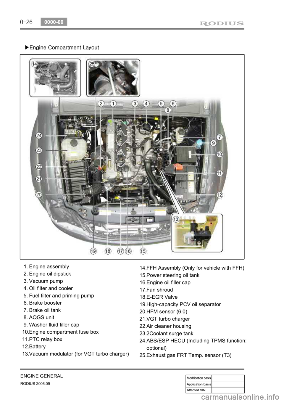
▶Engine Compartment Layout
Engine assembly
Engine oil dipstick
Vacuum pump
Oil filter and cooler
Fuel filter and priming pump
Brake booster
Brake oil tank
AQGS unit
Washer fluid filler cap
Engine compartment fuse box
PTC relay box
Battery
Vacuum modulator (for VGT turbo charger) 1.
2.
3.
4.
5.
6.
7.
8.
9.
10.
11.
12.
13.FFH Assembly (Only for vehicle with FFH)
Power steering oil tank
Engine oil filler cap
Fan shroud
E-EGR Valve
High-capacity PCV oil separator
HFM sensor (6.0)
VGT turbo charger
Air cleaner housing
2Coolant surge tank
ABS/ESP HECU (Including TPMS function:
optional)
Exhaust gas FRT Temp. sensor (T3) 14.
15.
16.
17.
18.
19.
20.
21.
22.
23.
24.
25.
Page 216 of 465

0-4
RODIUS 2006.09
8010-10
CLUSTER
2. DESCRIPTIONS OF INDICATOR DISPLAY
1. Immobilizer indicator
2. Glow indicator
3. Winter mode indicator
4. Left turn signal indicator
5. Auto shift indicator (for automatic transmission)
6. Right turn signal indicator
7. Harzard indicator*
8. Engine check warning light
9. Cruise control indicator*
10. 4WD CHECK warning light
11. 4WD HIGH indicator
12. 4WD LOW indicator
13. Brake warning light14. Battery charge warning light
15. Seat belt reminder
16. Low fuel level warning light
17. Heated glass indicator
18. Door open warning light
19. High beam indicator
20. Engine oil pressure warning light
21. Air bag warning light
22. Water separator warning light
23. ABS warning light
24. EBD warning light
25. ESP warning light
Page 278 of 465

0-9
TRANSFER CASE
RODIUS 2006.09
3410-01
Ring, snap
Ring, snap
Ring, snap
Bearing
Hub, circular
Asm. -shaft, input
Plate, thrust
Gear, sun
Snap ring
Asm. -carrier (complete)
Hub reduction
Asm. -shaft, main
Clamp hose
Hose
Filter
Asm. -coil, electric
Asm. -cam/coil hsg.
Ring, snap
Armature
Hub, lockup
Spring, sleeve return
Collar, lockup
Sprocket, driving
Spring, return
Rail, shift
Fork, shift
Asm. -fork, shift
Cam, electric shift
Spring, torsion
Spacer
Shaft, shift
Ring, retaining
Asm. -case, transfer
Barb, breather 1.
2.
3.
4.
5.
6.
7.
8.
9.
10.
11.
12.
13.
14.
15.
16.
17.
18.
19.
20.
21.
22.
23.
24.
25.
26.
27.
28.
29.
30.
31.
32.
33.
34.Decal
Shaft, output
Deflector, dust
Magnet
Ring snap
Sprocket lower
Spacer
Chain
Ring retaining
Bearing
Bearing
Cover
Bendable clip
Bolt, Metric
Seal, oil
Washer
Nut, Metric
Flange, companion
Seal, oil
Spacer
Tone wheel (upper)
Nut, Metric
Clip, “J”
Bolt, hex head
Bracket, relay mounting
Locking clip
Connector
Bolt, hex head
Capscrew, hex head
Asm. -motor, electric
Seal, oil
Plug, pipe
Sealing Compound 35.
36.
37.
38.
39.
40.
41.
42.
43.
44.
45.
46.
47.
48.
49.
50.
51.
52.
53.
54.
55.
56.
57.
58.
59.
60.
61.
62.
63.
64.
65.
66.
Page 302 of 465
0-8
RODIUS 2006.09
3240-01
TORQUE ON DEMAND
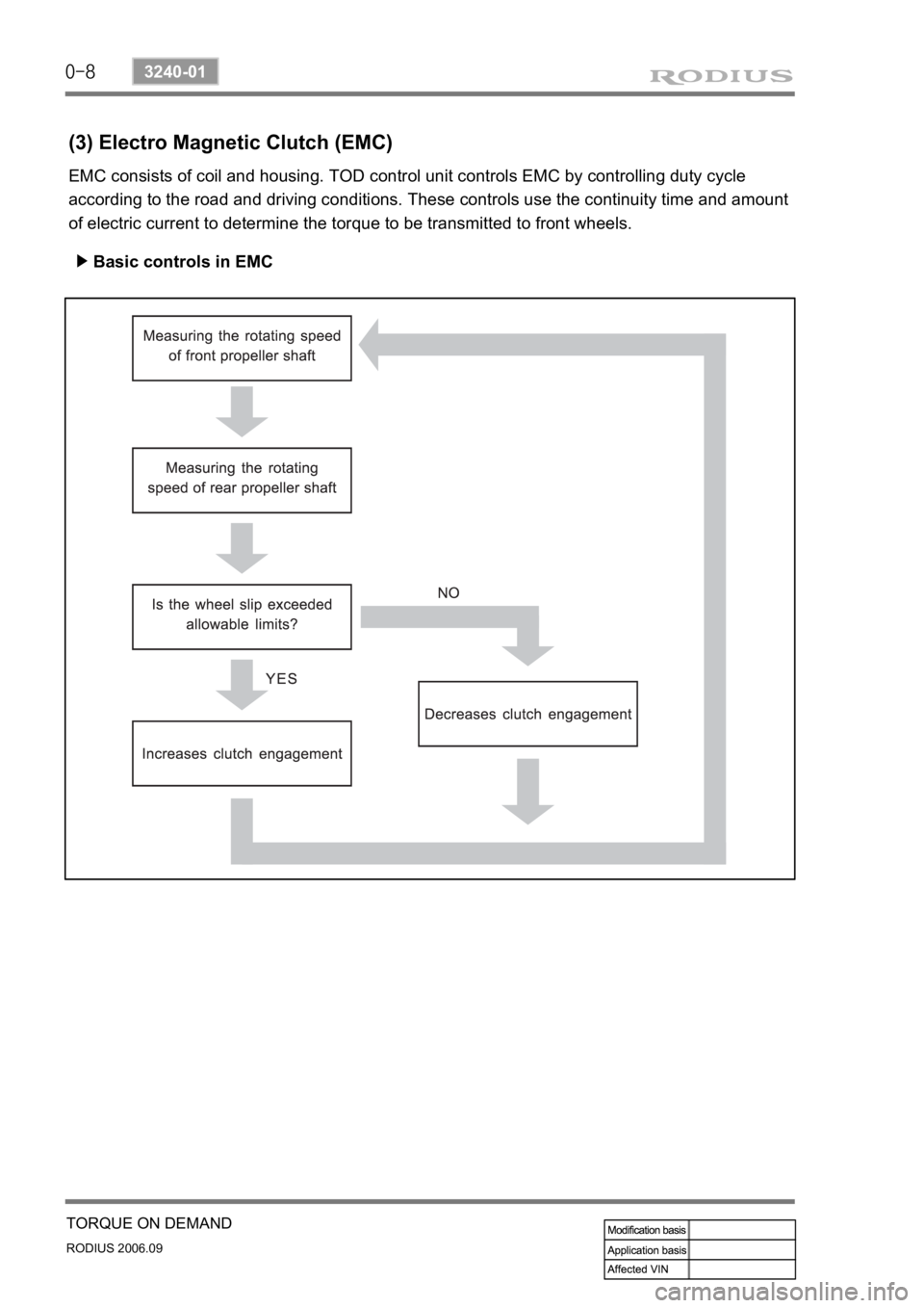
(3) Electro Magnetic Clutch (EMC)
EMC consists of coil and housing. TOD control unit controls EMC by controlling duty cycle
according to the road and driving conditions. These controls use the continuity time and amount
of electric current to determine the torque to be transmitted to front wheels.
Basic controls in EMC ▶
Page 313 of 465

0-5
SUSPENSION SYSTEM
RODIUS 2006.09
4111-01
3. STRUCTURE OF SHOCK ABSORBER AND COIL SPRING
1) front coil spring
▶ Specification
Page 316 of 465

0-8
RODIUS 2006.09
4111-01
SUSPENSION SYSTEM
4) rear coil spring
Steel for high tensional spring is adapted.
Maintain more than 20 mm of freeplay when compressed.
Spring seat applied. ·
·
·
▶ Specification
Page 321 of 465
0-7
BRAKS SYSTEM
RODIUS 2006.09
4830-01
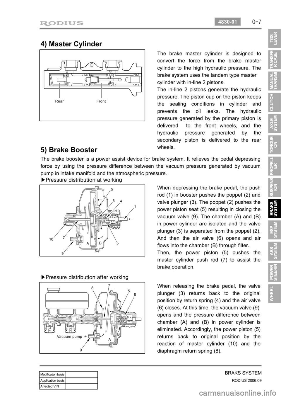
4) Master Cylinder
The brake master cylinder is designed to
convert the force from the brake maste
r
cylinder to the high hydraulic pressure. The
brake system uses the tandem type master
cylinder with in-line 2 pistons.
The in-line 2 pistons generate the hydraulic
pressure. The piston cup on the piston keeps
the sealing conditions in cylinder and
prevents the oil leaks. The hydraulic
pressure generated by the primary piston is
delivered to the front wheels, and the
hydraulic pressure generated by the
secondary piston is delivered to the rea
r
wheels.
5) Brake Booster
The brake booster is a power assist device for brake system. It relieves the pedal depressing
force by using the pressure difference between the vacuum pressure generated by vacuum
pump in intake manifold and the atmospheric pressure.
▶Pressure distribution at working
When depressing the brake pedal, the push
rod (1) in booster pushes the poppet (2) and
valve plunger (3). The poppet (2) pushes the
power piston seat (5) resulting in closing the
vacuum valve (9). The chamber (A) and (B)
in power cylinder are isolated and the valve
plunger (3) is separated from the poppet (2).
And then the air valve (6) opens and ai
r
flows into the chamber (B) through filter.
Then, the power piston (5) pushes the
master cylinder push rod (7) to assist the
brake operation.
▶Pressure distribution after working
When releasing the brake pedal, the valve
plunger (3) returns back to the original
position by return spring (4) and the air valve
(6) closes. At this time, the vacuum valve (9)
opens and the pressure difference between
chamber (A) and (B) in power cylinder is
eliminated. Accordingly, the power piston (5)
returns back to original position by the
reaction of master cylinder (10) and the
diaphragm return spring (8).
Page 322 of 465
0-8
RODIUS 2006.09
4830-01
BRAKS SYSTEM
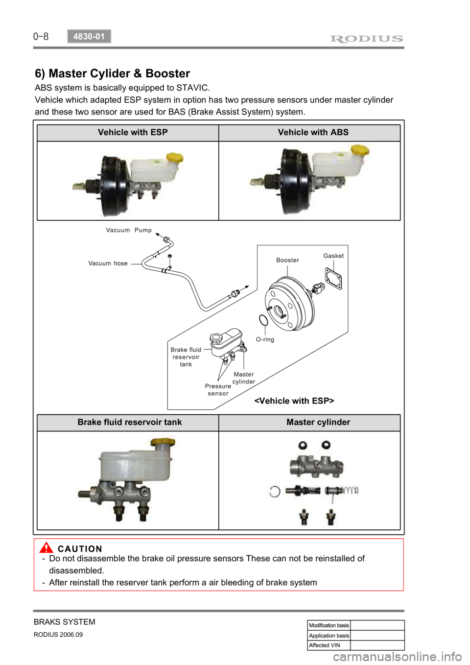
6) Master Cylider & Booster
ABS system is basically equipped to STAVIC.
Vehicle which adapted ESP system in option has two pressure sensors under master cylinder
and these two sensor are used for BAS (Brake Assist System) system.
Do not disassemble the brake oil pressure sensors These can not be reinstalled of
disassembled.
After reinstall the reserver tank perform a air bleeding of brake system
-
-
Vehicle with ESP Vehicle with ABS
Brake fluid reservoir tank Master cylinder
Page 336 of 465
0-16
RODIUS 2006.09
4892-01
ESP SYSTEM
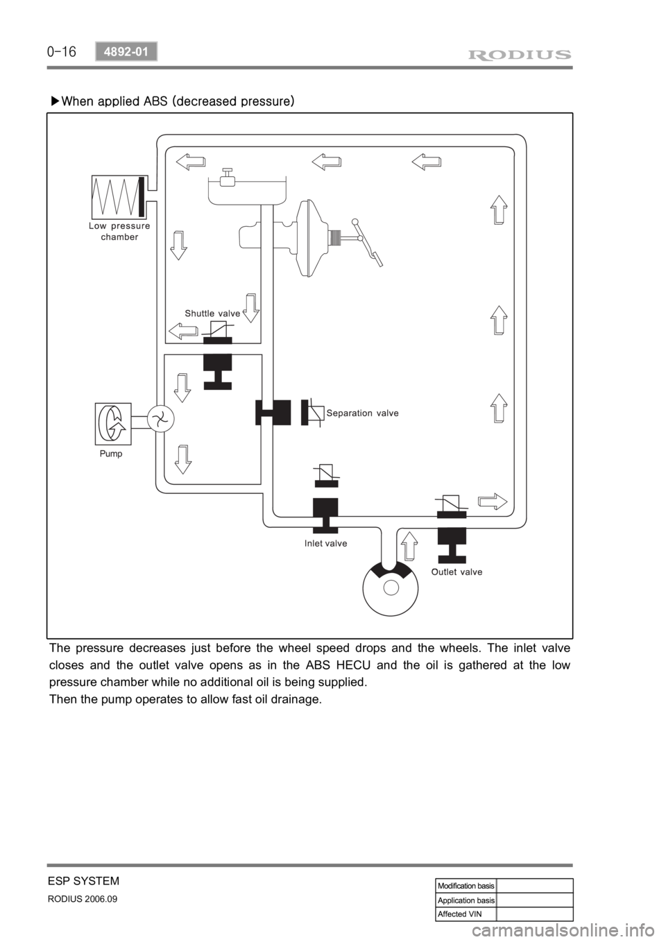
▶When applied ABS (decreased pressure)
The pressure decreases just before the wheel speed drops and the wheels. The inlet valve
closes and the outlet valve opens as in the ABS HECU and the oil is gathered at the low
pressure chamber while no additional oil is being supplied.
Then the pump operates to allow fast oil drainage.