ignition SSANGYONG RODIUS 2007 Owner's Manual
[x] Cancel search | Manufacturer: SSANGYONG, Model Year: 2007, Model line: RODIUS, Model: SSANGYONG RODIUS 2007Pages: 465, PDF Size: 56.32 MB
Page 206 of 465

0-33
STICS
RODIUS 2006.09
8710-01
12) Time Lag Power Window Control
The power window is turned off when turning the ignition key to “ON” position.
The power window relay is turned “ON” for 90 seconds (T1) when turning the ignition
key to “OFF” position.
However, the power window relay stays on for 90 seconds (T2) when the ignition key is
turned to “OFF” position while the door is opened.
The power window relay is turned “ON” again for 90 seconds (T2) just for once when
opening the door during its extended operation period of 90 seconds (T1).
The power window relay is turned “OFF” when closing the door during its extended
operation period of 90 seconds (T2). 1.
2.
3.
4.
Page 211 of 465
0-38
RODIUS 2006.09
8710-01
STICS
14) Theft Deterrent
(1) Description of Burglar Alarm Function
Description of Burglar Alarm Function ▶
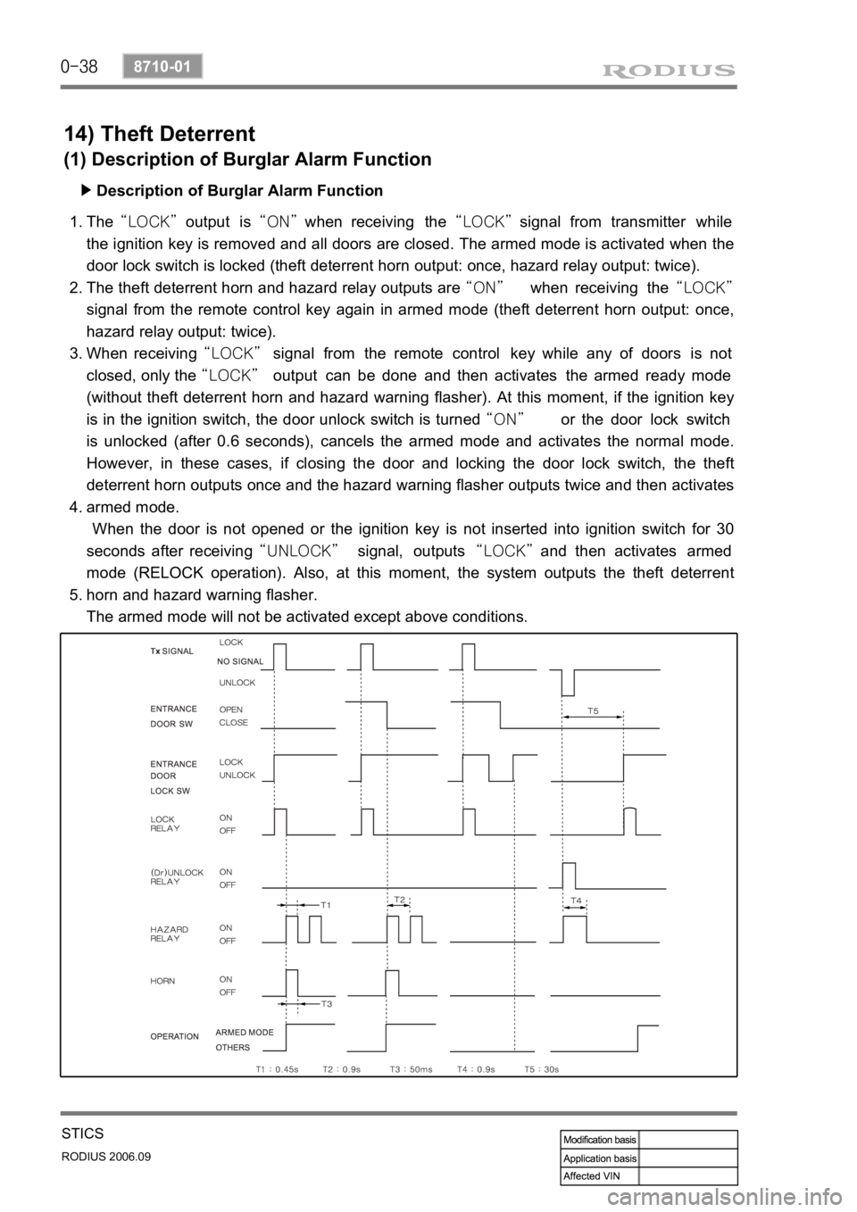
The “LOCK” output is “ON” when receiving the “LOCK” signal from transmitter while
the ignition key is removed and all doors are closed. The armed mode is activated when the
door lock switch is locked (theft deterrent horn output: once, hazard relay output: twice).
The theft deterrent horn and hazard relay outputs are “ON” when receiving the “LOCK”
signal from the remote control key again in armed mode (theft deterrent horn output: once,
hazard relay output: twice).
When receiving “LOCK” signal from the remote control key while any of doors is not
closed, only the “LOCK” output can be done and then activates the armed ready mode
(without theft deterrent horn and hazard warning flasher). At this moment, if the ignition key
is in the ignition switch, the door unlock switch is turned “ON” or the door lock switch
is unlocked (after 0.6 seconds), cancels the armed mode and activates the normal mode.
However, in these cases, if closing the door and locking the door lock switch, the theft
deterrent horn outputs once and the hazard warning flasher outputs twice and then activates
armed mode.
When the door is not opened or the ignition key is not inserted into ignition switch for 30
seconds after receiving “UNLOCK” signal, outputs “LOCK” and then activates armed
mode (RELOCK operation). Also, at this moment, the system outputs the theft deterrent
horn and hazard warning flasher.
The armed mode will not be activated except above conditions.
Ex) The armed mode will not be activated when the door is locked by the ignition key. 1.
2.
3.
4.
5.
Page 212 of 465
0-39
STICS
RODIUS 2006.09
8710-01
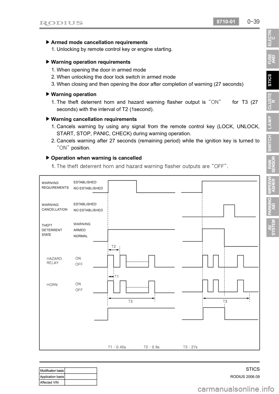
Armed mode cancellation requirements ▶
Unlocking by remote control key or engine starting. 1.
Warning operation requirements ▶
When opening the door in armed mode
When unlocking the door lock switch in armed mode
When closing and then opening the door after completion of warning (27 seconds) 1.
2.
3.
Warning operation ▶
The theft deterrent horn and hazard warning flasher output is “ON” for T3 (27
seconds) with the interval of T2 (1second). 1.
Warning cancellation requirements ▶
Cancels warning by using any signal from the remote control key (LOCK, UNLOCK,
START, STOP, PANIC, CHECK) during warning operation.
Cancels warning after 27 seconds (remaining period) while the ignition key is turned to
“ON” position. 1.
2.
Operation when warning is cancelled ▶
<007b008f008c0047009b008f008c008d009b0047008b008c009b008c00990099008c0095009b0047008f009600990095004700880095008b0047008f008800a100880099008b0047009e00880099009500900095008e0047008d00930088009a008f008c00
9900470096009c009b0097009c009b009a004700880099008c> “OFF”. 1.
Page 214 of 465
0-41
STICS
RODIUS 2006.09
8710-01
16) Auto Light Function
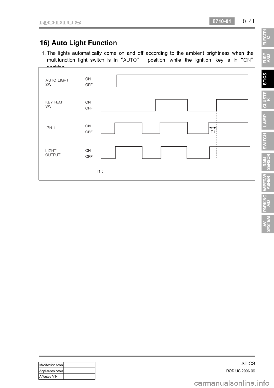
The lights automatically come on and off according to the ambient brightness when the
multifunction light switch is in “AUTO” position while the ignition key is in “ON”
position. 1.
Page 232 of 465

0-9
LAMP
RODIUS 2006.09
8310-01
4. Luggage room lamp
: one at center (12V - 5W)
Luggage room lamp is turned on
and off when the switch (1) is
pressed in and out.
Luggage lamp is turned on and of
f
when opening and closing one o
f
rear doors with the front room lamp
switch pressed in.
5. Glove box lamp
: one at center (12V - 5W)
6. Door courtesy lamp
: one at each door (12V - 5W)
Door courtesy lamp is turned on when
opening a door while the ignition switch
is in “ON” position.
Rear (third row set) room lamp
Rear (second row set) room lamp
Front room lamp
Glove box lamp
Center console lamp
Page 258 of 465
0-9
PARKING AID SYSTEM
RODIUS 2006.09
8790-04
3) Cautions on parking aid system
Note that the display does not show everything in the rear area.
Always check nobody, especially animals and children, is behind the vehicle.
Normal precautions when reversing should be maintained. *
*
The parking aid system is just a supplemental device to help your parking operation.
Always keep the safety precautions.
Do not press or shock the sensors by hitting or high-pressure water gun while washing, o
r
the sensors will be damaged.
If the system is in normal operating conditions, a short beep sounds when the gear selecto
r
lever is moved into “R” position with the ignition key “ON”.
If the system is in abnormal operating conditions, a beep sounds for 3 seconds when the
gear selector lever is moved into “R” position with the ignition key “ON” or engine
running. However, it is also occurred when the obstacle is within 50 cm from the rea
r
bumper. 1.
2.
3.
4.
5.
(1) The parking aid system will not work or improperly work under
following cases:
▶Certain obstacles that sensors can not detect
- Wires, ropes, chains.
- Cotton, sponge, clothes, snow that absorb ultrasonic waves.
- Obstacles lower than the bumper.
▶Not defective but improperly working
- When the sensing portion is frozen.
- When the sensing portion is covered by rain, water drops, snow or mud.
- When receiving other ultrasonic signals
(metal sound or air braking noises from heavy commercial vehicles).
- When a high-power radio is turned on.
▶Narrowed sensing area
- When the sensing portion is partially covered by snow or mud.
<00540047007a009c009900990096009c0095008b00900095008e0047009b008c00940097008c00990088009b009c0099008c00470096008d0047009a008c0095009a0096009900470090009a0047009b009600960047008f0090008e008f0047004f008800
97009700990096009f005500470096009d008c00990047005f>0°C) or too low (approx.
below -
30°C)
▶Not defective but may occur improper working
- When driving on the rough road, gravel road, hill and grass.
- When the bumper height is changed due to the heavy load.
- When the sensing portion is frozen.
- When the sensing portion is covered by rain, water drops, snow or mud.
- When receiving other ultrasonic signals
(metal sound or air braking noises from heavy commercial vehicles).
- When a high-power radio is turned on.
- When some accessories are attached in detecting ranges
Page 261 of 465
0-12
RODIUS 2006.09
8790-04
PARKING AID SYSTEM
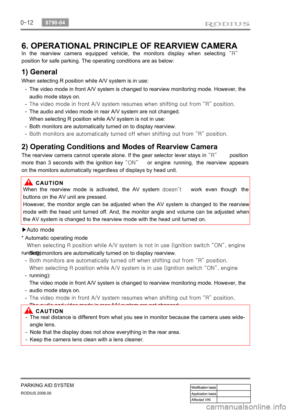
6. OPERATIONAL PRINCIPLE OF REARVIEW CAMERA
In the rearview camera equipped vehicle, the monitors display when selecting “R”
position for safe parking. The operating conditions are as below:
1) General
When selecting R position while A/V system is in use:
The video mode in front A/V system is changed to rearview monitoring mode. However, the
audio mode stays on.
<007b008f008c0047009d0090008b008c0096004700940096008b008c0047009000950047008d009900960095009b004700680056007d0047009a00a0009a009b008c009400470099008c009a009c0094008c009a0047009e008f008c00950047009a008f00
90008d009b00900095008e00470096009c009b0047008d0099>om “R” position.
The audio and video mode in rear A/V system are not changed.
When selecting R position while A/V system is not in use:
Both monitors are automatically turned on to display rearview.
<00690096009b008f00470094009600950090009b00960099009a004700880099008c00470088009c009b009600940088009b0090008a00880093009300a00047009b009c00990095008c008b00470096008d008d0047009e008f008c00950047009a008f00
90008d009b00900095008e00470096009c009b0047008d0099>om “R” position. -
-
-
-
-
2) Operating Conditions and Modes of Rearview Camera
The rearview camera cannot operate alone. If the gear selector lever stays in “R” position
more than 3 seconds with the ignition key “ON” or engine running, the rearview appears
on the monitors automatically regardless of displays by head unit.
When the rearview mode is activated, the AV system doesn’t work even though the
buttons on the AV unit are pressed.
However, the monitor angle can be adjusted when the AV system is changed to the rearview
mode with the head unit turned off. And, the monitor angle and volume can be adjusted when
the AV system is changed to the rearview mode with the head unit turned on.
▶Auto mode
* Automatic operating mode
<004700470047007e008f008c00950047009a008c0093008c008a009b00900095008e00470079004700970096009a0090009b0090009600950047009e008f00900093008c004700680056007d0047009a00a0009a009b008c009400470090009a0047009500
96009b0047009000950047009c009a008c0047004f0070008e>nition switch “ON”, engine
running):
Both monitors are automatically turned on to display rearview.
<00690096009b008f00470094009600950090009b00960099009a004700880099008c00470088009c009b009600940088009b0090008a00880093009300a00047009b009c00990095008c008b00470096008d008d0047009e008f008c00950047009a008f00
90008d009b00900095008e00470096009c009b0047008d0099>om “R” position.
<007e008f008c00950047009a008c0093008c008a009b00900095008e00470079004700970096009a0090009b0090009600950047009e008f00900093008c004700680056007d0047009a00a0009a009b008c009400470090009a0047009000950047009c00
9a008c0047004f0070008e00950090009b0090009600950047>switch “ON”, engine
running):
The video mode in front A/V system is changed to rearview monitoring mode. However, the
audio mode stays on.
<007b008f008c0047009d0090008b008c0096004700940096008b008c0047009000950047008d009900960095009b004700680056007d0047009a00a0009a009b008c009400470099008c009a009c0094008c009a0047009e008f008c00950047009a008f00
90008d009b00900095008e00470096009c009b0047008d0099>om “R” position.
The audio and video mode in rear A/V system are not changed. -
-
-
-
-
The real distance is different from what you see in monitor because the camera uses wide-
angle lens.
Note that the display does not show everything in the rear area.
Keep the camera lens clean with a lens cleaner. -
-
-
Page 349 of 465
0-10
RODIUS 2006.09
4892-01
ABS SYSTEM
3. ON-VEHICLE SERVICE
(1) Electronic system service precautions
Take care to avoid electronic brake control module (HECU) circuit overloading. In testing for
opens or shorts, do not ground or apply voltage to any circuit unless instructed to do so by the
diagnostic procedure. Test circuits only with a high-impedance multi-meter. Never remove o
r
apply power to any control module with the ignition switch in the ON position. Always turn the
ignition to the OFF position before removing or connecting battery cables, fuses or connectors.
(2) General service precautions
Disconnect the HECU connector before performing any vehicle welding work using an electric
arc welder. Do not attempt to disassemble any component designated as nonserviceable. The
hydraulic modulator and the HECU can be seperated. (There is however no access to repai
r
the each components.)
(3) Bleeding system
Replacement modulators are shipped already filled and bled. In normal procedures requiring
removal of the modulator, such as to replace the HECU, air will not enter the modulator, and
normal bleeding will be all that is needed.
If air enters the hydraulic modulator, or if an unfilled modulator is installed, use the brake
bleeding program in the scan tool to bleed the modulator. Manual bleeding of the hydraulic
modulator is not possible.
1) Service Precautions
Brake Fluid may irritate eyes and skin. In case of contact, take the following actions:
Eye contact - rinse thoroughly with water.
Skin contact - wash with soap and water.
Ingestion - consult a physician immediately. -
-
-
To help avoid personal injury due to poor braking. DO NOT Tap into the vehicle’s
brake system to operate a trailer brake system.
When fasteners are removed, always reinstall them at the same location from which they
were removed. If a fastener needs to be replaced, use the correct part number fastener
for is not available, a fastener of equal size and strength (or stronger) may be used.
Fasteners that are not reused, and those requiring thread-locking compound will be
called out. The correct torque values must be used when installing fasteners that require
them. If the above procedures are not followed, parts or system damage could result.
Page 355 of 465

0-16
RODIUS 2006.09
4892-01
ABS SYSTEM
Service precautions ▶
Observe the following general precautions during any ABS/TCS service. Failure to adhere to
these precautions may result in ABS/TCS system damage.
Disconnect the EBCM harness connector before performing the electric welding procedures.
Carefully note the routing of the ABS/TCS wiring and wiring components during removal.
The ABS/ TCS components are extremely sensitive to EMI (eletromagnetic interference).
Proper mounting is critical during component service.
Disconnect the EBCM connector with the ignition OFF.
Do not hang the suspension components from the wheel speed sensor cables. The cables
may be damaged.
Do not use petroleum based fluids in the master cylinder. Do not use any containers
previously used for petroleum based fluids. Petroleum causes swelling and distortion of the
rubber components in the hydraulic brake system, resulting in water entering the system
and lowering the fluid boiling point. 1.
2.
3.
4.
5.
Page 385 of 465

0-13
AIR CONDITIONING SYSTEM
RODIUS 2006.09
6810-20
4. SENSORS AND ACTUATORS
1) Sun Sensor
It is installed on the upper left end of instrument panel. It is using characteristics that the
amount of current changes according to amount of light on the photosensitive surface. Photo
diode, converts the changes in light intensity into electrical changes, detects the amount of light
coming through windshield and changes it into current and then sends the signal to FATC
controller.
(1) Inspection
Remove the sun sensor and measure the current between terminals under sunlight.
Measure the current again under shade. It is in normal conditions if the measured value is
less than the measured value under sunlight.
Turn the ignition switch to “ON” position.
Measure the voltage to the sun sensor from FATC connector. (approx. 2.5 V under sunlight
and 4.8 V under shade.)
If the voltage value cannot be measured, check the circuit for open. If the measured value is
within the specified range, replace the FATC controller. 1.
2.
3.
4.
5.