brake fluid SSANGYONG RODIUS 2007 Service Manual
[x] Cancel search | Manufacturer: SSANGYONG, Model Year: 2007, Model line: RODIUS, Model: SSANGYONG RODIUS 2007Pages: 465, PDF Size: 56.32 MB
Page 122 of 465
0-26
RODIUS 2006.09
0000-00
ENGINE GENERAL
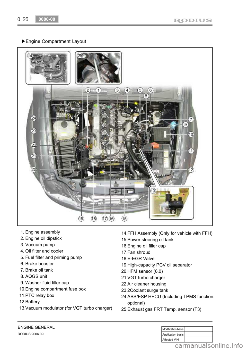
▶Engine Compartment Layout
Engine assembly
Engine oil dipstick
Vacuum pump
Oil filter and cooler
Fuel filter and priming pump
Brake booster
Brake oil tank
AQGS unit
Washer fluid filler cap
Engine compartment fuse box
PTC relay box
Battery
Vacuum modulator (for VGT turbo charger) 1.
2.
3.
4.
5.
6.
7.
8.
9.
10.
11.
12.
13.FFH Assembly (Only for vehicle with FFH)
Power steering oil tank
Engine oil filler cap
Fan shroud
E-EGR Valve
High-capacity PCV oil separator
HFM sensor (6.0)
VGT turbo charger
Air cleaner housing
2Coolant surge tank
ABS/ESP HECU (Including TPMS function:
optional)
Exhaust gas FRT Temp. sensor (T3) 14.
15.
16.
17.
18.
19.
20.
21.
22.
23.
24.
25.
Page 161 of 465

0-7
ELECTRIC GENERAL
RODIUS 2006.09
0000-00
Sub condenser
Theft deterrent horn (under the washer fluid reservoir)
PTC power supply relay
(PTC system equipped vehicle)
ABS (ESP) HECU
(under the battery)
Fuse and relay box in engine compartmentBrake pressure sensor
Page 322 of 465
0-8
RODIUS 2006.09
4830-01
BRAKS SYSTEM
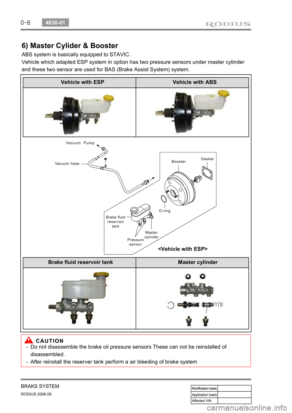
6) Master Cylider & Booster
ABS system is basically equipped to STAVIC.
Vehicle which adapted ESP system in option has two pressure sensors under master cylinder
and these two sensor are used for BAS (Brake Assist System) system.
Do not disassemble the brake oil pressure sensors These can not be reinstalled of
disassembled.
After reinstall the reserver tank perform a air bleeding of brake system
-
-
Vehicle with ESP Vehicle with ABS
Brake fluid reservoir tank Master cylinder
Page 331 of 465
0-11
ESP SYSTEM
RODIUS 2006.09
4892-01
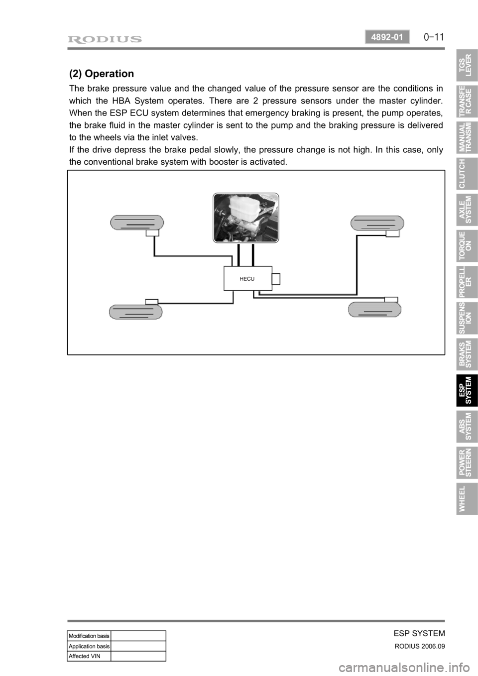
(2) Operation
The brake pressure value and the changed value of the pressure sensor are the conditions in
which the HBA System operates. There are 2 pressure sensors under the master cylinder.
When the ESP ECU system determines that emergency braking is present, the pump operates,
the brake fluid in the master cylinder is sent to the pump and the braking pressure is delivered
to the wheels via the inlet valves.
If the drive depress the brake pedal slowly, the pressure change is not high. In this case, only
the conventional brake system with booster is activated.
Page 335 of 465
0-15
ESP SYSTEM
RODIUS 2006.09
4892-01
<0d96006c007a00770047006f00a0008b00990088009c00930090008a0047009c00950090009b00470090009500470090008b009300900095008e004700880095008b00470095009600990094008800930047008900990088009200900095008e0047009700
96009a0090009b009000960095>
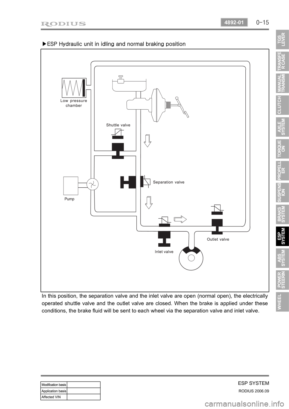
In this position, the separation valve and the inlet valve are open (normal open), the electrically
operated shuttle valve and the outlet valve are closed. When the brake is applied under these
conditions, the brake fluid will be sent to each wheel via the separation valve and inlet valve.
Page 343 of 465
0-4
RODIUS 2006.09
4892-01
ABS SYSTEM
2. GENERAL INFORMATION
The aim of the ABS is to mmaintain steerability and driving stability and to take the burden off
the driver. If the stopping distance is shorter on some road surfaces (carriageway conditions),
this is a gift of physics and not a development aim.
ABS is a device which senses that one or more of the wheels are locking up during braking. It
monitors the rotational speeds of the wheels and reduces hydraulic pressure to any wheel it
senses locking up. It is controlled by both mechanical and electronic components. When you
apply the brakes, the ABS will regulate the flow of brake fluid being delivered to the brake
calipers. By the use of electronic computers, the brakes rapidly alternate (at a rate of 30 times
per second) from full pressure to full release.
1) DRIVING PHYSICS
To give you a better understanding of the tasks and functions of ABS, we will first look at the
physics principles.
(1) The Stopping Distance
The stopping distance depends on the vehicle weight and initial speed when braking starts.
This also applies for vehicle with ABS, where ABS always tries to set an optimum brake force
on each wheel. As great forces are exerted between the tires and the carriageway when
braking, even with ABS the wheels may scream and rubber is left on the road. With an
ABS
skid mark one may be able to clearly recognize the tire profile. The skid mark of an ABS vehicle
does not however leave any hint of the speed of the vehicle in the case of an accident, as it can
only be clearly drawn at the start of braking.
(2) Brake Force on a Wheel
The maximum possible brake force on a wheel depends on the wheel load and the adhesion
coefficient between tire and carriageway. With a low adhesion coefficient the brake force, which
can be obtained is very low. You are bound to know the result already from driving on winte
r
roads. With a high adhesion coefficient on a dry road, the brake force, which can be obtained,
is considerably higher. The brake force, which can be obtained, can be calculated from below
formula:
Page 349 of 465
0-10
RODIUS 2006.09
4892-01
ABS SYSTEM
3. ON-VEHICLE SERVICE
(1) Electronic system service precautions
Take care to avoid electronic brake control module (HECU) circuit overloading. In testing for
opens or shorts, do not ground or apply voltage to any circuit unless instructed to do so by the
diagnostic procedure. Test circuits only with a high-impedance multi-meter. Never remove o
r
apply power to any control module with the ignition switch in the ON position. Always turn the
ignition to the OFF position before removing or connecting battery cables, fuses or connectors.
(2) General service precautions
Disconnect the HECU connector before performing any vehicle welding work using an electric
arc welder. Do not attempt to disassemble any component designated as nonserviceable. The
hydraulic modulator and the HECU can be seperated. (There is however no access to repai
r
the each components.)
(3) Bleeding system
Replacement modulators are shipped already filled and bled. In normal procedures requiring
removal of the modulator, such as to replace the HECU, air will not enter the modulator, and
normal bleeding will be all that is needed.
If air enters the hydraulic modulator, or if an unfilled modulator is installed, use the brake
bleeding program in the scan tool to bleed the modulator. Manual bleeding of the hydraulic
modulator is not possible.
1) Service Precautions
Brake Fluid may irritate eyes and skin. In case of contact, take the following actions:
Eye contact - rinse thoroughly with water.
Skin contact - wash with soap and water.
Ingestion - consult a physician immediately. -
-
-
To help avoid personal injury due to poor braking. DO NOT Tap into the vehicle’s
brake system to operate a trailer brake system.
When fasteners are removed, always reinstall them at the same location from which they
were removed. If a fastener needs to be replaced, use the correct part number fastener
for is not available, a fastener of equal size and strength (or stronger) may be used.
Fasteners that are not reused, and those requiring thread-locking compound will be
called out. The correct torque values must be used when installing fasteners that require
them. If the above procedures are not followed, parts or system damage could result.
Page 350 of 465

0-11
ABS SYSTEM
RODIUS 2006.09
4892-01
Use only DOT-3 equivalent hydraulic brake fluid. The use of DOT-5 (silicone) brake fluid is
not recommended. Reduced brake performance or durability may result.
Avoid spilling brake fluid on any the vehicle’s painted surfaces, wiring, cables or
electrical connectors. Brake fluid will damage paint and electrical connections. If any fluid is
spilled on the vehicle, flush the area with water to lessen the damage.
Page 355 of 465

0-16
RODIUS 2006.09
4892-01
ABS SYSTEM
Service precautions ▶
Observe the following general precautions during any ABS/TCS service. Failure to adhere to
these precautions may result in ABS/TCS system damage.
Disconnect the EBCM harness connector before performing the electric welding procedures.
Carefully note the routing of the ABS/TCS wiring and wiring components during removal.
The ABS/ TCS components are extremely sensitive to EMI (eletromagnetic interference).
Proper mounting is critical during component service.
Disconnect the EBCM connector with the ignition OFF.
Do not hang the suspension components from the wheel speed sensor cables. The cables
may be damaged.
Do not use petroleum based fluids in the master cylinder. Do not use any containers
previously used for petroleum based fluids. Petroleum causes swelling and distortion of the
rubber components in the hydraulic brake system, resulting in water entering the system
and lowering the fluid boiling point. 1.
2.
3.
4.
5.
Page 360 of 465

0-21
ABS SYSTEM
RODIUS 2006.09
4892-01
(3) COMPONENTS DESCRIPTION
HECU (Hydraulic & Electronic Control Unit) ▶
Motor Pump ▶
Valve Body ▶
HECU consists of motor pump (1), solenoid
valve (2) and ECU (3).
ECU connector has 47 pins and the numbe
r
of valves in valve body is 6 when equipped
with only ABS and 12 when equipped with
ESP system.
The motor is operated when ABS is
activated. The cam-shaped output shaft o
f
the motor enables the brake system to
receive and supply the brake fluid during the
motor operation.
The cam bushing is installed between
plungers and it draws and discharges the
brake fluid.