change time SSANGYONG RODIUS 2007 Service Manual
[x] Cancel search | Manufacturer: SSANGYONG, Model Year: 2007, Model line: RODIUS, Model: SSANGYONG RODIUS 2007Pages: 465, PDF Size: 56.32 MB
Page 149 of 465
0-12
RODIUS 2006.09
0000-00
CDEF(Catalytic Disel Particulate Filter)
6) CDPF Over Load (Notice of Beginning CPF Regeneration Mode
- P1430)
The CDPF system enters the regeneration mode when the mileage is around 600 ~ 1,200
km, depending on the driving condition and driving habits. At this moment, the ECU
performs the CDPF regeneration process; however, the driver may not notice anything
because there is no engine warning or other signals indicating such process.
The control logic in the regeneration process is to increase the exhaust gas temperature by
increasing the fuel injection during post injection process and controlling the intake ai
r
amount(throttle body), and no significant change can be noticed in the vehicle condition.
The engine CHECK lamp flashes but there is no decrease in engine torque.
The engine CHECK lamp flashes to inform the driver when there is an over load due to soot
accumulation because the regeneration temperature cannot be reached due to low speed,
even though CDPF regeneration is in process.
The CDPF regeneration process must be completed by driving for 15-20 minutes at a speed
higher than 80 km/h to solve this problem.
The engine CHECK lamp flashes when CDPF is over loaded; therefore, 4) above must be
performed in this case. 1.
2.
3.
4.
5.
7) CDPF's Excessive Soot Accumulation (P0432)
When the vehicle is driven at a low speed (5-10 km/h) for a long time or long distance, the
soot over accumulates inside the CDPF and the combustion temperature cannot be reached
even by performing the soot combustion process. In this case, this DTC is generated.
This is more serious situation than the CDPF over load condition. Therefore, the engine
power is decreased to protect the system and the engine CHECK lamp is turned on.
Blow the soot between the engine and the exhaust system several times and clear the DTC
to solve this problem. If the same DTC is generated again, check the system according to
the DTC description related to the differential pressure sensor.
* This DTC is actually generated mostly due to the related system malfunction, such as
differential pressure sensor malfunction. 1.
2.
3.
Page 204 of 465
0-31
STICS
RODIUS 2006.09
8710-01
(4) Auto Door Lock
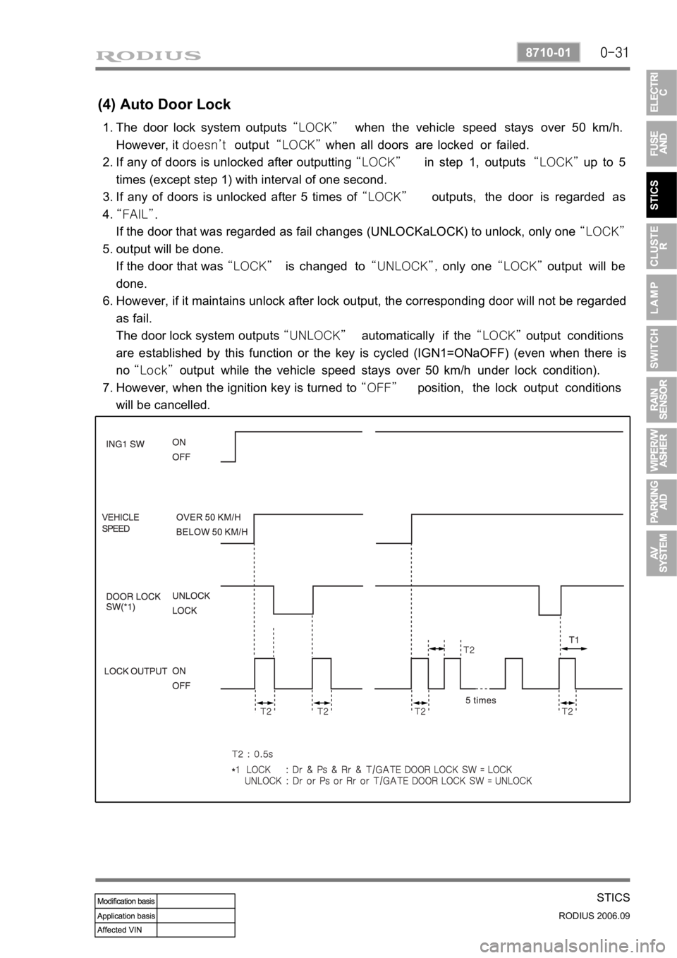
The door lock system outputs “LOCK” when the vehicle speed stays over 50 km/h.
However, it doesn’t output “LOCK” when all doors are locked or failed.
If any of doors is unlocked after outputting “LOCK” in step 1, outputs “LOCK” up to 5
times (except step 1) with interval of one second.
If any of doors is unlocked after 5 times of “LOCK” outputs, the door is regarded as
“FAIL”.
If the door that was regarded as fail changes (UNLOCKaLOCK) to unlock, only one “LOCK”
output will be done.
If the door that was “LOCK” is changed to “UNLOCK”, only one “LOCK” output will be
done.
However, if it maintains unlock after lock output, the corresponding door will not be regarded
as fail.
The door lock system outputs “UNLOCK” automatically if the “LOCK” output conditions
are established by this function or the key is cycled (IGN1=ONaOFF) (even when there is
no “Lock” output while the vehicle speed stays over 50 km/h under lock condition).
However, when the ignition key is turned to “OFF” position, the lock output conditions
will be cancelled.
The “FAIL” condition of the door will be erased when the ignition key is turned to
“OFF” position. 1.
2.
3.
4.
5.
6.
7.
Page 254 of 465
0-5
PARKING AID SYSTEM
RODIUS 2006.09
8790-04
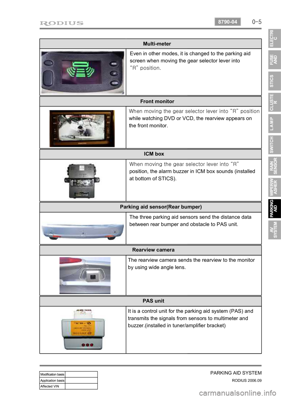
Multi-meter
Front monitor ICM box
Even in other modes, it is changed to the parking aid
screen when moving the gear selector lever into
“R” position.
When moving the gear selector lever into “R”
position
while watching DVD or VCD, the rearview appears on
the front monitor.
When moving the gear selector lever into “R”
position, the alarm buzzer in ICM box sounds (installed
at bottom of STICS).
Parking aid sensor(Rear bumper)
The three parking aid sensors send the distance data
between rear bumper and obstacle to PAS unit.
Rearview camera
The rearview camera sends the rearview to the monitor
by using wide angle lens.
PAS unit
It is a control unit for the parking aid system (PAS) and
transmits the signals from sensors to multimeter and
buzzer.(installed in tuner/amplifier bracket)
Page 299 of 465
0-5
TORQUE ON DEMAND
RODIUS 2006.09
3240-01
2. GENERAL DESCRIPTION
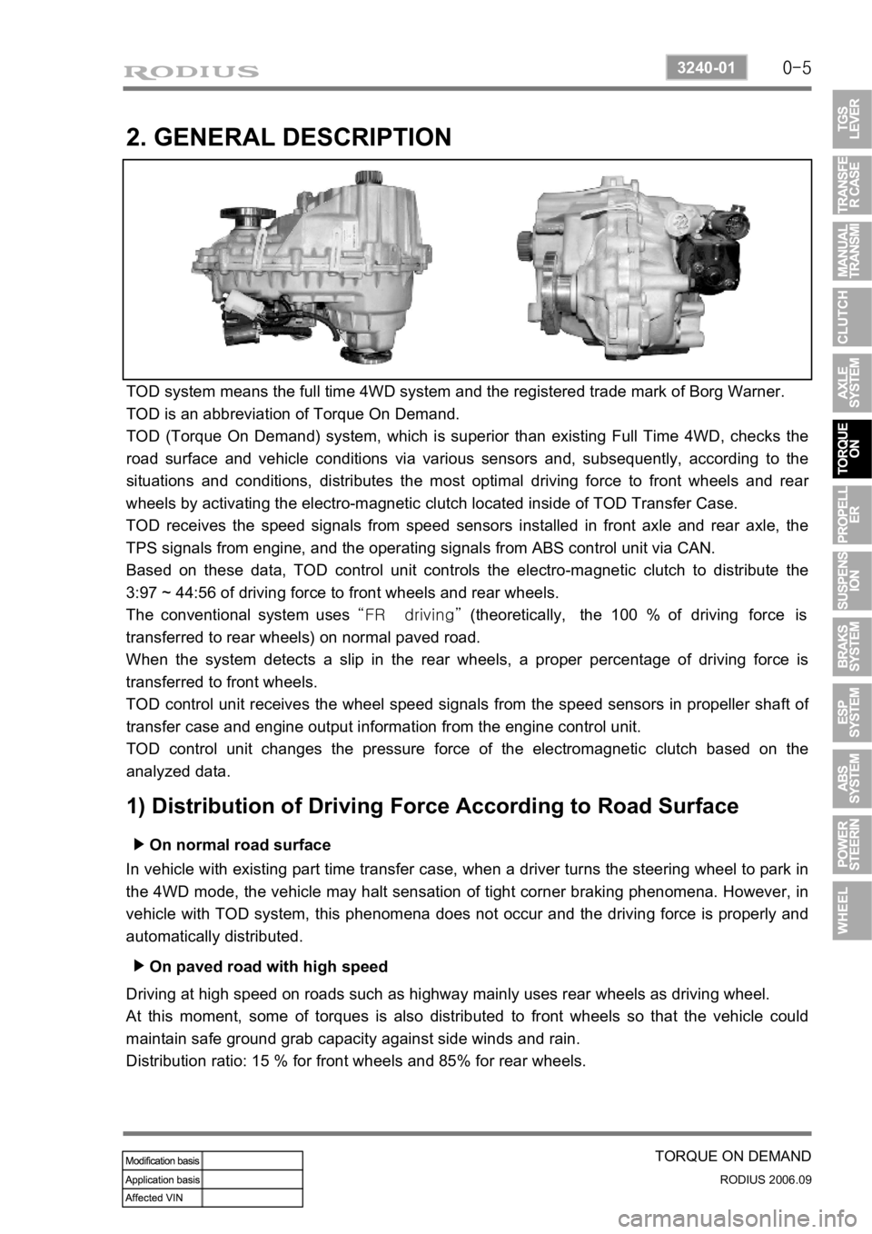
TOD system means the full time 4WD system and the registered trade mark of Borg Warner.
TOD is an abbreviation of Torque On Demand.
TOD (Torque On Demand) system, which is superior than existing Full Time 4WD, checks the
road surface and vehicle conditions via various sensors and, subsequently, according to the
situations and conditions, distributes the most optimal driving force to front wheels and rea
r
wheels by activating the electro-magnetic clutch located inside of TOD Transfer Case.
TOD receives the speed signals from speed sensors installed in front axle and rear axle, the
TPS signals from engine, and the operating signals from ABS control unit via CAN.
Based on these data, TOD control unit controls the electro-magnetic clutch to distribute the
3:97 ~ 44:56 of driving force to front wheels and rear wheels.
The conventional system uses “FR driving” (theoretically, the 100 % of driving force is
transferred to rear wheels) on normal paved road.
When the system detects a slip in the rear wheels, a proper percentage of driving force is
transferred to front wheels.
TOD control unit receives the wheel speed signals from the speed sensors in propeller shaft o
f
transfer case and engine output information from the engine control unit.
TOD control unit changes the pressure force of the electromagnetic clutch based on the
analyzed data.
1) Distribution of Driving Force According to Road Surface
On normal road surface ▶
In vehicle with existing part time transfer case, when a driver turns the steering wheel to park in
the 4WD mode, the vehicle may halt sensation of tight corner braking phenomena. However, in
vehicle with TOD system, this phenomena does not occur and the driving force is properly and
automatically distributed.
On paved road with high speed ▶
Driving at high speed on roads such as highway mainly uses rear wheels as driving wheel.
At this moment, some of torques is also distributed to front wheels so that the vehicle could
maintain safe ground grab capacity against side winds and rain.
Distribution ratio: 15 % for front wheels and 85% for rear wheels.
Page 327 of 465
0-7
ESP SYSTEM
RODIUS 2006.09
4892-01
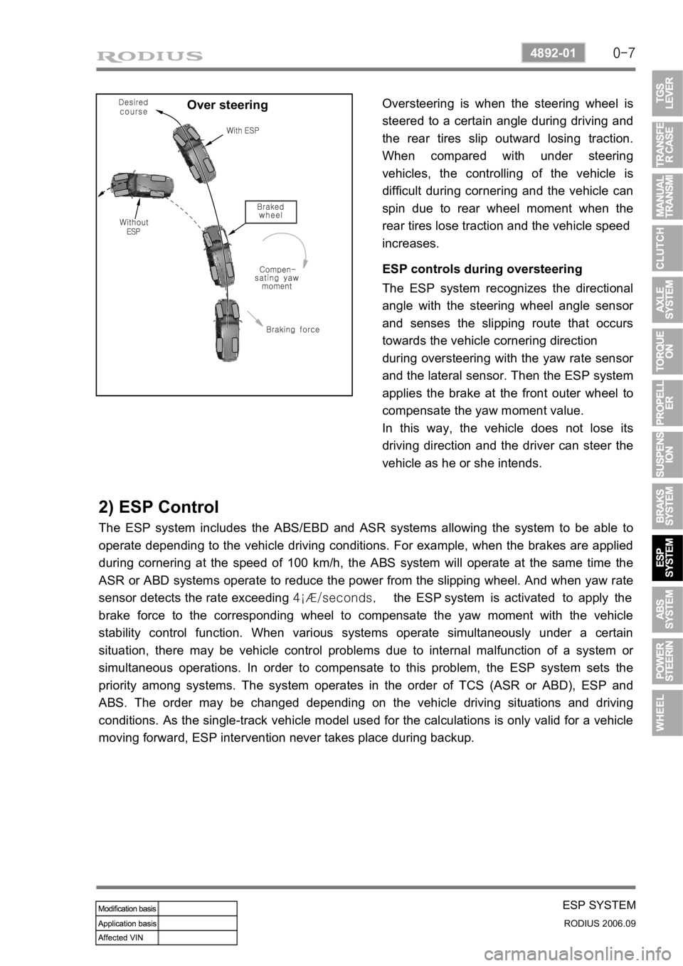
Over steeringOversteering is when the steering wheel is
steered to a certain angle during driving and
the rear tires slip outward losing traction.
When compared with under steering
vehicles, the controlling of the vehicle is
difficult during cornering and the vehicle can
spin due to rear wheel moment when the
rear tires lose traction and the vehicle speed
increases.
ESP controls during oversteering
The ESP system recognizes the directional
angle with the steering wheel angle senso
r
and senses the slipping route that occurs
towards the vehicle cornering direction
during oversteering with the yaw rate senso
r
and the lateral sensor. Then the ESP system
applies the brake at the front outer wheel to
compensate the yaw moment value.
In this way, the vehicle does not lose its
driving direction and the driver can steer the
vehicle as he or she intends.
2) ESP Control
The ESP system includes the ABS/EBD and ASR systems allowing the system to be able to
operate depending to the vehicle driving conditions. For example, when the brakes are applied
during cornering at the speed of 100 km/h, the ABS system will operate at the same time the
ASR or ABD systems operate to reduce the power from the slipping wheel. And when yaw rate
sensor detects the rate exceeding 4¡Æ/seconds, the ESP system is activated to apply the
brake force to the corresponding wheel to compensate the yaw moment with the vehicle
stability control function. When various systems operate simultaneously under a certain
situation, there may be vehicle control problems due to internal malfunction of a system o
r
simultaneous operations. In order to compensate to this problem, the ESP system sets the
priority among systems. The system operates in the order of TCS (ASR or ABD), ESP and
ABS. The order may be changed depending on the vehicle driving situations and driving
conditions. As the single-track vehicle model used for the calculations is only valid for a vehicle
moving forward, ESP intervention never takes place during backup.
Page 328 of 465
0-8
RODIUS 2006.09
4892-01
ESP SYSTEM
2) ESP Control
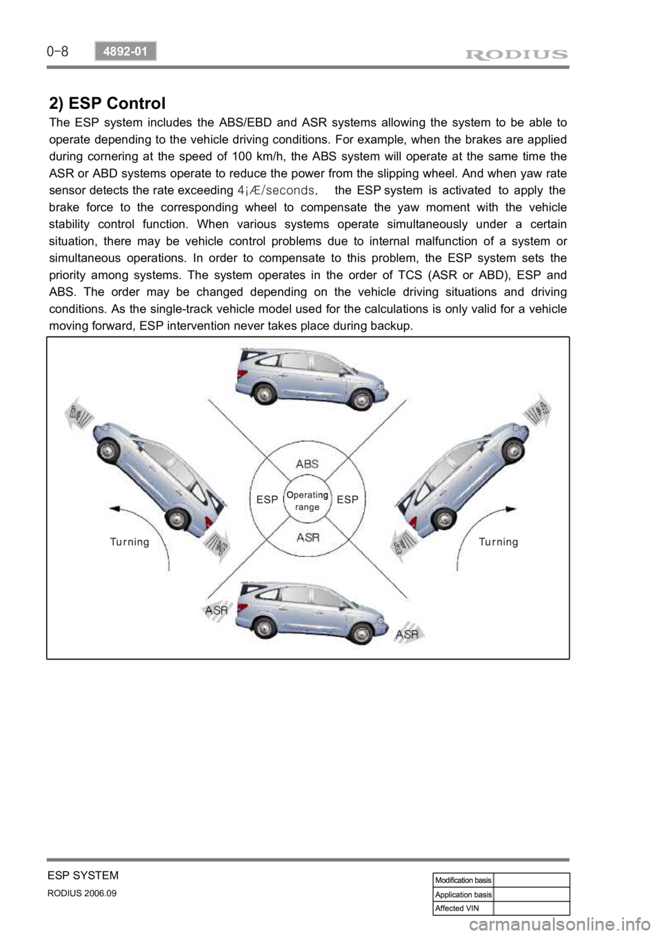
The ESP system includes the ABS/EBD and ASR systems allowing the system to be able to
operate depending to the vehicle driving conditions. For example, when the brakes are applied
during cornering at the speed of 100 km/h, the ABS system will operate at the same time the
ASR or ABD systems operate to reduce the power from the slipping wheel. And when yaw rate
sensor detects the rate exceeding 4¡Æ/seconds, the ESP system is activated to apply the
brake force to the corresponding wheel to compensate the yaw moment with the vehicle
stability control function. When various systems operate simultaneously under a certain
situation, there may be vehicle control problems due to internal malfunction of a system o
r
simultaneous operations. In order to compensate to this problem, the ESP system sets the
priority among systems. The system operates in the order of TCS (ASR or ABD), ESP and
ABS. The order may be changed depending on the vehicle driving situations and driving
conditions. As the single-track vehicle model used for the calculations is only valid for a vehicle
moving forward, ESP intervention never takes place during backup.
Page 334 of 465
0-14
RODIUS 2006.09
4892-01
ESP SYSTEM
(1) System Overview
When equipped with ABS, the braking force at each wheel will be controlled with 3-channel 4-
sensor method. And when equipped with ESP, 4 wheels will be controlled independently with 4-
channel method. (When controlling ABS system only, it will be operated with 3-channel
method.) When compared to the vehicle equipped with ABS/EBD only, the internal hydraulic
circuit has a normally-open separation valve and a shuttle valve in primary circuit and in
secondary circuit. When the vehicle brakes are not applied during engine running or when
applying the non-ABS operating brakes, the normally-open separation valve and the inlet valve
are open, whereas the normally-closed shuttle valve and the outlet valve are closed. When the
ESP system is operating, the normally-open separation valve will be closed by the solenoid
valve operation and the hydraulic circuit will be established by the shuttle valve. Then, the inlet
and outlet valves will be
closed or open depending on the braking pressure increase, decrease or unchanged
conditions.
<0d96007b008f008c0047009e00880099009500900095008e004700930088009400970047008a00960094008c009a004700960095004700880095008b0047009e00880099009500900095008e00470089008c008c00970047009a0096009c0095008b009a00
47009e008f008c00950047009b008f008c0047006c007a0077> is operating
▶Driving feeling when the ESP is operating
<0d96007500960090009a008c004700880095008b0047009d0090008900990088009b0090009600950047009b008f0088009b0047008b00990090009d008c00990047009a008c0095009a008c009a0047009e008f008c00950047009b008f008c0047006c00
7a007700470090009a004700960097008c00990088009b0090>ng When the ESP operates during vehicle movement, the ESP warning lamp on the instrument
panel flickers and beep comes on every 0.1 seconds. The ESP operation shows that the
vehicle stability is extremely unstable and it is used to warn the driver. The ESP system is just a
supplementary system for the vehicle motion and it cannot control the vehicle when it exceeds
the physical limits. Do not solely rely on the system but be advised to drive the vehicle safely.
When the ESP system activates, the driving feeling can be different depending on vehicle
driving conditions. For example, you will feel differently when the ESP system is activated
during when ABS is operating with the brakes applied and when brakes are not applied on a
curve. Thus, the ESP system would make the driver feel more abruptly when the brakes are
applied during the ESP system activation.
The ESP system may transfer noise and vibration to the driver due to the pressure changes
caused by the motor and valve operations in a very short period of time. Extreme cornering will
trigger the ESP operation and this will make the driver feel noise and vibration due to sudden
brake application. Also, the ESP system controls the engine output. So, the driver may notice
the engine output decrease even when the accelerator pedal is being applied.
Page 390 of 465
0-18
RODIUS 2006.09
6810-20
AIR CONDITIONING SYSTEM
2) AQS Operation
The AQS operates under air conditioner AUTO mode or when the AQS switch is pressed under
manual mode. It requires preheating time (for seconds) for operation and the module and
sensor are integrated. (However, it operates only when the DEF (defroster) switch on the ai
r
conditioner switch panel is not pressed in.)
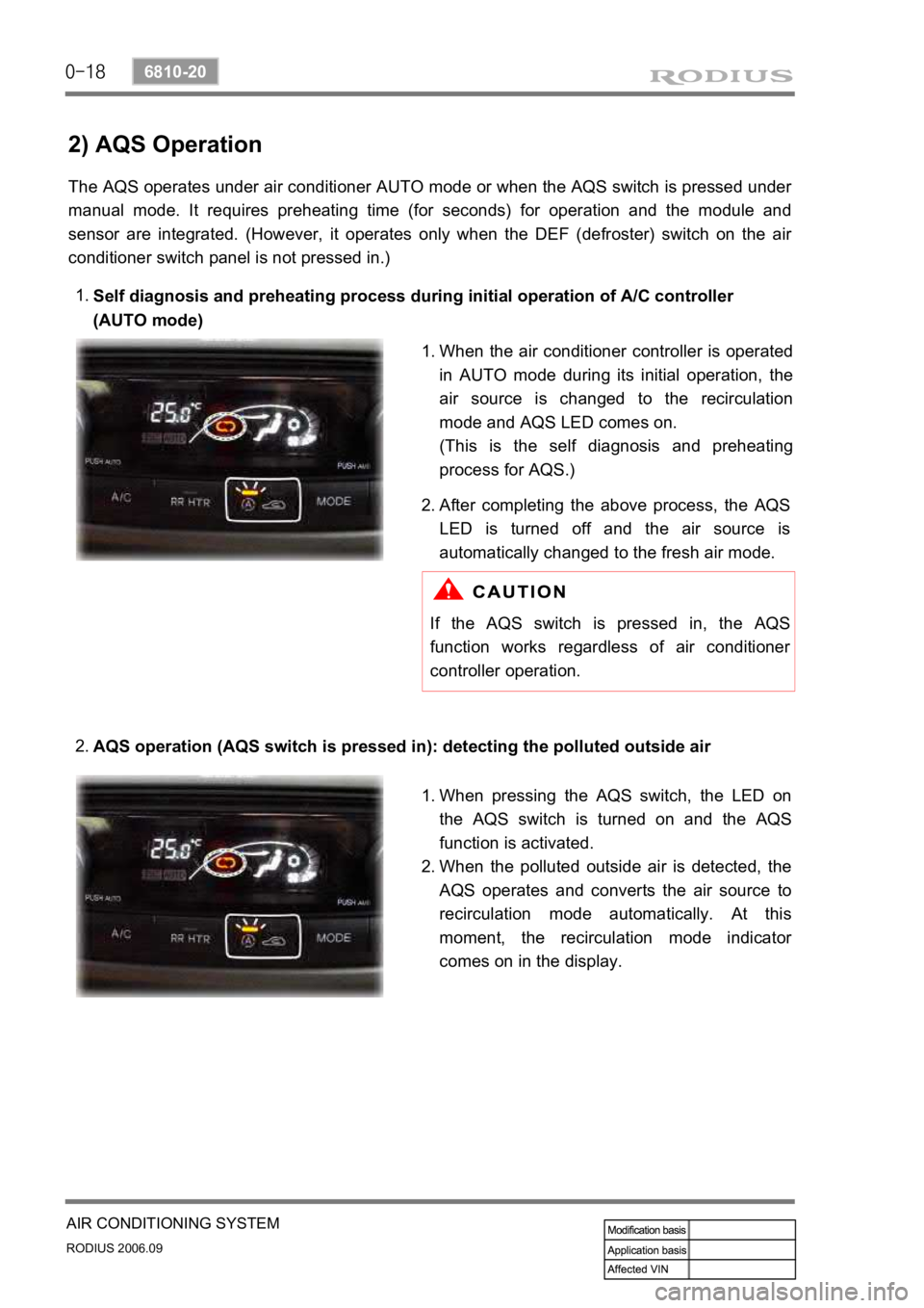
Self diagnosis and preheating process during initial operation of A/C controller
(AUTO mode)
1.
AQS operation (AQS switch is pressed in): detecting the polluted outside air
2.
When the air conditioner controller is operated
in AUTO mode during its initial operation, the
air source is changed to the recirculation
mode and AQS LED comes on.
(This is the self diagnosis and preheating
process for AQS.)
1.
After completing the above process, the
AQS
LED is turned off and the air source is
automatically changed to the fresh air mode.
2.
If the AQS switch is pressed in, the AQS
function works regardless of air conditioner
controller operation.
When pressing the AQS switch, the LED on
the AQS switch is turned on and the
AQS
function is activated.
When the polluted outside air is detected, the
AQS operates and converts the air source to
recirculation mode automatically. At this
moment, the recirculation mode indicato
r
comes on in the display.
1.
2.