display SSANGYONG RODIUS 2007 Service Manual
[x] Cancel search | Manufacturer: SSANGYONG, Model Year: 2007, Model line: RODIUS, Model: SSANGYONG RODIUS 2007Pages: 465, PDF Size: 56.32 MB
Page 85 of 465

09-3
ENGINE CONTROL SYSTEM
RODIUS 2006.09
0000-00
1522-16ENGINE CONTROL SYSTEM
1. ENGINE DATA DISPLAY TABLE
Page 192 of 465

0-19
STICS
RODIUS 2006.09
8710-01
4) Door Ajar Warning
The warning light in indicator display comes on when opening any of driver’s door,
passenger’s door, rear door or tailgate while the vehicle speed is below 6 km/h (V1).
The warning light goes off when closing the door under step 1.
The warning light blinks when the vehicle speed is over 10 km/h (V1) for more than 2
seconds while the warning light is turned on.
The warning light blinks when a door is opened while the vehicle speed is over 10 km/h (V1)
(while the warning light is turned off).
The warning light goes off when closing the door under step 3.
The warning light comes on when the vehicle speed is below 3 km/h (V2) under step 3. 1.
2.
3.
4.
5.
6.
Page 193 of 465

0-20
RODIUS 2006.09
8710-01
STICS
5) Seat Belt Warning
The seat belt warning light comes on and the chime buzzer in the ICM box sounds for 6
<009a008c008a00960095008b009a0047009e008f008c00950047009b009c0099009500900095008e0047009b008f008c00470090008e00950090009b00900096009500470092008c00a00047009b0096004702c80076007502c90047008d00990096009400
4702c80076006d006d02c9005500470070008d0047009b008f>e seat belt is fastened
<0089008c008d00960099008c0047009b009c0099009500900095008e0047009b008f008c00470090008e00950090009b00900096009500470092008c00a00047009b0096004702c80076007502c9004700970096009a0090009b0090009600950053004700
9b008f008c0047009e00880099009500900095008e00470093>ight in the indicator
display blinks for 6 seconds, however, the chime buzzer does not sound.
The seat belt warning light goes off and the chime buzzer in the ICM box stops when turning
the ignition switch to “OFF” position.
The chime buzzer stops and the seat belt warning light stays on for the specified duration (6
seconds) when fastening the seat belt during the warning operation.
The seat belt warning light comes on and the chime buzzer sounds for 6 seconds again
when unfastening the seat belt during fastening operation. 1.
2.
3.
4.
Page 210 of 465

0-37
STICS
RODIUS 2006.09
8710-01
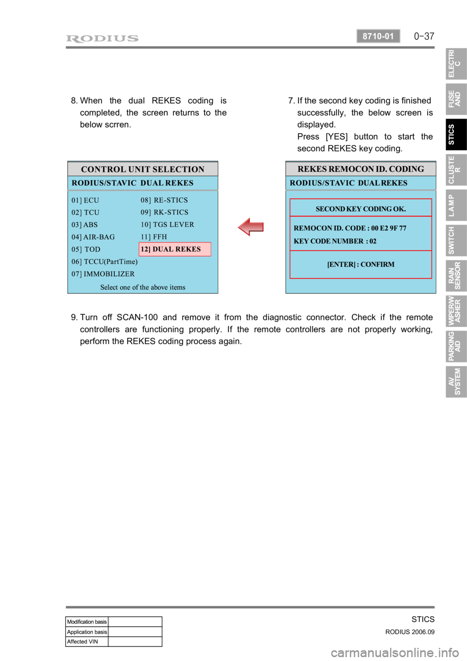
When the dual REKES coding is
completed, the screen returns to the
below scrren. 8.
If the second key coding is finished
successfully, the below screen is
displayed.
Press [YES] button to start the
second REKES key coding. 7.
Turn off SCAN-100 and remove it from the diagnostic connector. Check if the remote
controllers are functioning properly. If the remote controllers are not properly working,
perform the REKES coding process again. 9.
Page 215 of 465

0-3
CLUSTER
RODIUS 2006.09
8010-10
8010-01CLUSTER
1. APPEARANCE OF METER CLUSTER AND INDICATOR
DISPLAY
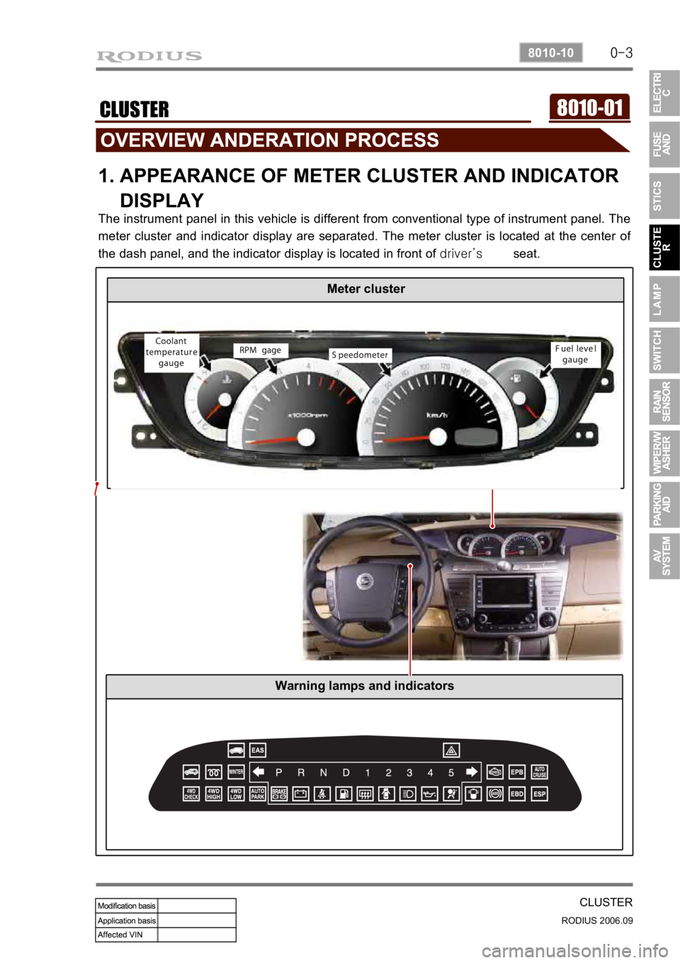
The instrument panel in this vehicle is different from conventional type of instrument panel. The
meter cluster and indicator display are separated. The meter cluster is located at the center o
f
the dash panel, and the indicator display is located in front of driver’s seat.
Meter cluster
Warning lamps and indicators
Page 216 of 465

0-4
RODIUS 2006.09
8010-10
CLUSTER
2. DESCRIPTIONS OF INDICATOR DISPLAY
1. Immobilizer indicator
2. Glow indicator
3. Winter mode indicator
4. Left turn signal indicator
5. Auto shift indicator (for automatic transmission)
6. Right turn signal indicator
7. Harzard indicator*
8. Engine check warning light
9. Cruise control indicator*
10. 4WD CHECK warning light
11. 4WD HIGH indicator
12. 4WD LOW indicator
13. Brake warning light14. Battery charge warning light
15. Seat belt reminder
16. Low fuel level warning light
17. Heated glass indicator
18. Door open warning light
19. High beam indicator
20. Engine oil pressure warning light
21. Air bag warning light
22. Water separator warning light
23. ABS warning light
24. EBD warning light
25. ESP warning light
Page 220 of 465

0-8
RODIUS 2006.09
8010-10
CLUSTER
4. FUNCTION DESCRIPTION AND INSPECTION OF
METER
CLUSTER
1) Tachometer - Engine RPM Display
The tachometer indicates engine speed in revolutions per minute. Multiply 1,000 to the current
number, then it will be the current number of engine revolutions.
Under the normal engine operating temperature, the proper idling speed is 700~800 rpm. The
red zone (danger rpm range) starts from 4,500 rpm.
1. Connect the tachometer for tune-up test and start the engine.
2. Eliminate the hysteresis by tapping the tachometer.
3. Compare the values on the tester and tachometer and replace the tachometer if the
tolerance
is excessive.
If the tachometer pointer vibrates, stands at a certain range or sounds abnormal noise, there
could be defectives in tachometer. If there is a difference between actual engine speed (rpm)
and reading from tachometer, connect a scanner and then compare the value on tachomete
r
with the reading from scanner.
Danger range (red zone)
Page 222 of 465

0-10
RODIUS 2006.09
8010-10
CLUSTER
3) Fuel Level Gauge
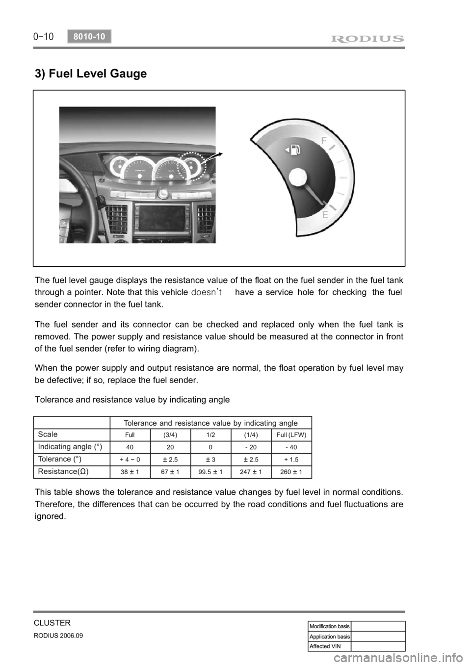
The fuel level gauge displays the resistance value of the float on the fuel sender in the fuel tank
through a pointer. Note that this vehicle doesn’t have a service hole for checking the fuel
sender connector in the fuel tank.
The fuel sender and its connector can be checked and replaced only when the fuel tank is
removed. The power supply and resistance value should be measured at the connector in front
of the fuel sender (refer to wiring diagram).
When the power supply and output resistance are normal, the float operation by fuel level may
be defective; if so, replace the fuel sender.
Tolerance and resistance value by indicating angle
This table shows the tolerance and resistance value changes by fuel level in normal conditions.
Therefore, the differences that can be occurred by the road conditions and fuel fluctuations are
ignored.
Page 223 of 465

0-11
CLUSTER
RODIUS 2006.09
8010-10
4) Coolant Temperature Gauge
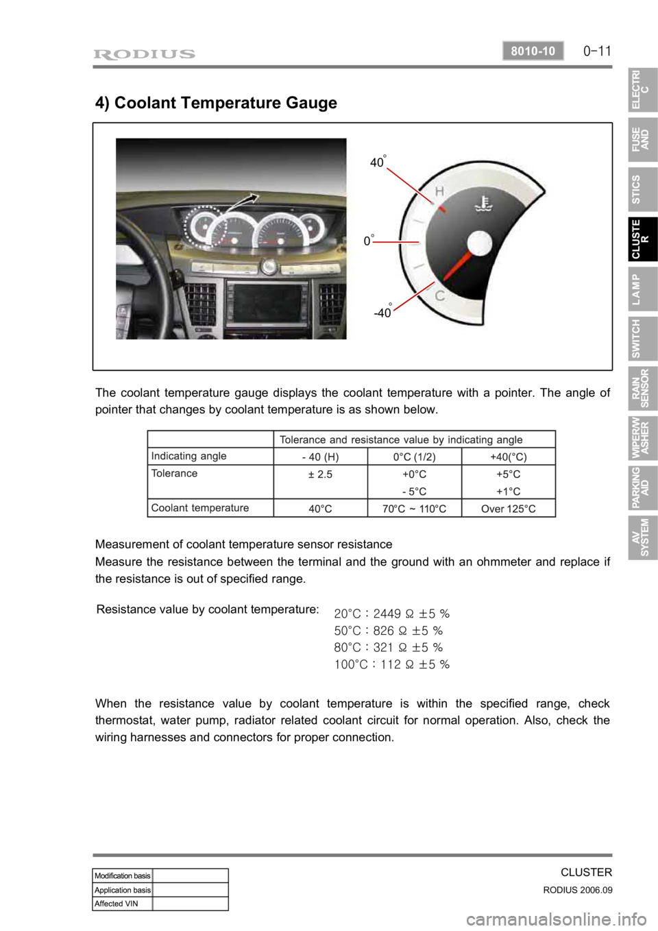
The coolant temperature gauge displays the coolant temperature with a pointer. The angle of
pointer that changes by coolant temperature is as shown below.
Measurement of coolant temperature sensor resistance
Measure the resistance between the terminal and the ground with an ohmmeter and replace i
f
the resistance is out of specified range.
Resistance value by coolant temperature:
20°C : 2449 Ω ±5 %
50°C : 826 Ω ±5 %
80°C : 321 Ω ±5 %
100°C : 112 Ω ±5 %
When the resistance value by coolant temperature is within the specified range, check
thermostat, water pump, radiator related coolant circuit for normal operation. Also, check the
wiring harnesses and connectors for proper connection.
-40 040° °°
Page 225 of 465

0-13
CLUSTER
RODIUS 2006.09
8010-10
5. CIRCUIT DIAGRAM OF INDICATOR DISPLAY