tank SSANGYONG RODIUS 2007 Service Manual
[x] Cancel search | Manufacturer: SSANGYONG, Model Year: 2007, Model line: RODIUS, Model: SSANGYONG RODIUS 2007Pages: 465, PDF Size: 56.32 MB
Page 79 of 465

07-8
RODIUS 2006.09
0000-00
COOLING SYSTEM
Radiator
Electric fan
Shroud
Deaeration tube
Clamp
Deaeration hose (radiator)
Electric fan mounting bracket
Bolt (M6, 8 pieces)
Bolt (M6, 4 pieces)
Bolt (M6, 4 pieces)
Upper radiator insulator
Lower radiator insulator
Plate
Clip 1.
2.
3.
4.
5.
6.
7.
8.
9.
10.
11.
12.
13.
14.Inlet hose
Outlet hose
3 way hose
Deaeration hose (reserver tank)
Clamp
Clamp
Make up hose holder
Reserver tank
Bolt (M6, 2 piece)
Cooling fan
Viscous clutch
Bolt (M6, 1 piece)
Bolt (M6, 3 piece) 15.
16.
17.
18.
19.
20.
21.
22.
23.
24.
25.
26.
27.
Page 122 of 465

0-26
RODIUS 2006.09
0000-00
ENGINE GENERAL
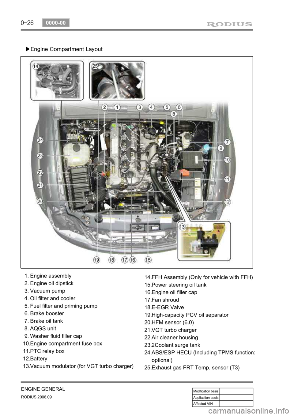
▶Engine Compartment Layout
Engine assembly
Engine oil dipstick
Vacuum pump
Oil filter and cooler
Fuel filter and priming pump
Brake booster
Brake oil tank
AQGS unit
Washer fluid filler cap
Engine compartment fuse box
PTC relay box
Battery
Vacuum modulator (for VGT turbo charger) 1.
2.
3.
4.
5.
6.
7.
8.
9.
10.
11.
12.
13.FFH Assembly (Only for vehicle with FFH)
Power steering oil tank
Engine oil filler cap
Fan shroud
E-EGR Valve
High-capacity PCV oil separator
HFM sensor (6.0)
VGT turbo charger
Air cleaner housing
2Coolant surge tank
ABS/ESP HECU (Including TPMS function:
optional)
Exhaust gas FRT Temp. sensor (T3) 14.
15.
16.
17.
18.
19.
20.
21.
22.
23.
24.
25.
Page 222 of 465

0-10
RODIUS 2006.09
8010-10
CLUSTER
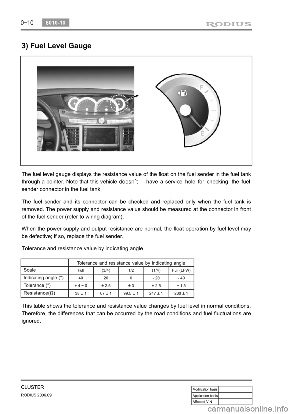
3) Fuel Level Gauge
The fuel level gauge displays the resistance value of the float on the fuel sender in the fuel tank
through a pointer. Note that this vehicle doesn’t have a service hole for checking the fuel
sender connector in the fuel tank.
The fuel sender and its connector can be checked and replaced only when the fuel tank is
removed. The power supply and resistance value should be measured at the connector in front
of the fuel sender (refer to wiring diagram).
When the power supply and output resistance are normal, the float operation by fuel level may
be defective; if so, replace the fuel sender.
Tolerance and resistance value by indicating angle
This table shows the tolerance and resistance value changes by fuel level in normal conditions.
Therefore, the differences that can be occurred by the road conditions and fuel fluctuations are
ignored.
Page 322 of 465

0-8
RODIUS 2006.09
4830-01
BRAKS SYSTEM
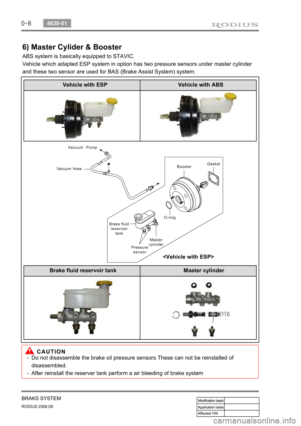
6) Master Cylider & Booster
ABS system is basically equipped to STAVIC.
Vehicle which adapted ESP system in option has two pressure sensors under master cylinder
and these two sensor are used for BAS (Brake Assist System) system.
Do not disassemble the brake oil pressure sensors These can not be reinstalled of
disassembled.
After reinstall the reserver tank perform a air bleeding of brake system
-
-
Vehicle with ESP Vehicle with ABS
Brake fluid reservoir tank Master cylinder
Page 367 of 465

0-8
RODIUS 2006.09
4610-00
POWER STEERING SYSTEM
3. POWER STEERING PUMP
The vane type pump that is connected to engine by belt is used for the power steering system.
This pump generates and controls a proper hydraulic pressure and flows by using the flow
control valve and pressure relief valve.
The flow control valve regulates the excessive amount of discharging oil. When the steering
wheel is stationary or the oil circuit is blocked, the pressure relief valve returns the ove
r
pressurized oil to the oil reservoir.
4. OIL RESERVOIR
The oil reservoir sends the oil to the power steering pump and receives the oil from the power
steering gear.
The oil level in the reservoir depends on the steering wheel positions. therefore, measure the oil
level when the steering wheel is positioned at straight ahead direction (neutral).
Steering pump Reservoir tank