torque SSANGYONG RODIUS 2012 Service Manual
[x] Cancel search | Manufacturer: SSANGYONG, Model Year: 2012, Model line: RODIUS, Model: SSANGYONG RODIUS 2012Pages: 715, PDF Size: 79.36 MB
Page 136 of 715

01-210000-00
9. TIGHTENING TORQUE OF STANDARD BOLTS
Tightening Torque By Bolt Specification ▶
Metric bolt strength is embossed on the head
of each bolt. The strength of bolt can be
classified as 4T, 7T, 8.8T, 10.9T, 11T and
12.9T in general.
Observe standard tightening torque during
bolt tightening works and can adjust torque to
be proper within 15 % if necessary. Try not to
over max. allowable tightening torque if not
required to do so. 1.
2.Determine extra proper tightening torque if
tightens with washer or packing.
If tightens bolts on the below materials, be
sure to determine the proper torque. 3.
4.
Aluminum alloy: Tighten to 80 % o
f
above torque table.
Plastics: Tighten to 20 % of above torque
table. ·
·
Page 142 of 715

02-6
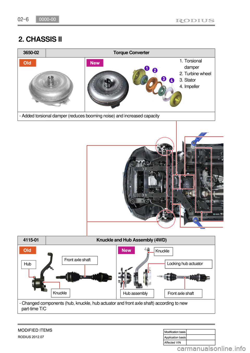
3650-02 Torque Converter
- Added torsional damper (reduces booming noise) and increased capacity
2. CHASSIS II
4115-01 Knuckle and Hub Assembly (4WD)
- Changed components (hub, knuckle, hub actuator and front axle shaft) according to new
part-time T/C
Torsional
damper
Turbine wheel
Stator
Impeller 1.
2.
3.
4.
Front axle shaft
Hub
Knuckle
Knuckle
Front axle shaftHub assembly
Locking hub actuator
Page 153 of 715

01-110000-00
5. STANDARD BOLTS SPECIFICATIONS
Metric bolt strength is embossed on the head of each bolt. The strength of bolt can be
classified as 4T, 7T, 8.8T, 10.9T, 11T and 12.9T in general.
Observe standard tightening torque during bolt tightening works and can adjust torque to be
proper within 15 % if necessary. Try not to over max. allowable tightening torque if not required
to do so.
Determine extra proper tightening torque if tightens with washer or packing.
If tightens bolts on the below materials, be sure to determine the proper torque. 1)
2)
3)
4)
Aluminum alloy: Tighten to 80 % of above torque table.
Plastics: Tighten to 20 % of above torque table. -
-
Page 154 of 715

01-12
6. TIGHTENING TORQUE
Name SizeNumbers of
fastenerTightening
torque (Nm)Note (total
tightening
torque)
Main bearing capM12×82 10 55±5Nm,
180˚ Not-reusable
Connecting rod capM9×52 8 40±5Nm,
90˚+10˚ 50 ~80Nm
Crankshaft rear sealM6×20 6 10±1Nm -
Oil pumpM8×35 3 25±2.5Nm -
Drive plateM10×22 8 45±5Nm,
90˚+10˚ Not-reusable
Isolation damper center
boltM18×50 1 200±20Nm,
180˚+20˚660 ~ 720Nm
Not-reusable
Oil panM6×20 18 10±1Nm -
M6×35 2 10±1Nm -
M6×85 2 10±1Nm -
M6×120 2 10±1Nm -
M8×40 2 25±2.5Nm -
Mounting nut for high
pressure pumpM14×1.5-8-1 1 65±5Nm -
Mounting bolt for high
pressure pumpM8×30 3 25±2.5Nm -
Cylinder headM13×150 12 85Nm
270°±10° -
Camshaft capM6×30 16 10±1Nm -
M8×60 4 25±2.5Nm -
Exhaust stud bolt 10 15±1.5Nm -
Exhaust sprocketM11×40 1 30±3Nm -
Chain tensioner screw
plug
M38×1.5 1 25±2.5Nm -
Coolant temperature
sensor1 20±2.0Nm -
Belt auto tensionerM8×30(LOW) 1 25±2.5Nm -
M10×75(U
pper) 1 55±5.5Nm -
Water pumpM6×50 7 10±1.0Nm -
Page 155 of 715

01-130000-00
T/C oil supply pipe M6(to block) 1 10±1.0Nm -
M6
(to turbocharger)1 17±2.0Nm-
T/C oil return pipeM6×16(to block)2 10±1Nm -
M6×16
(to turbocharger)210±1Nm -
EGR valveM8×223 25±2.5Nm -
EGR pipe bolt
(to exhaust manifold)M8×16 2 10±1Nm -
EGR pipe bolt
(to EGR cooler)M8×16 2 25±2.5Nm -
Name SizeNumbers of
fastenerTightening torque
(Nm)Note (total
tightening
torque)
Hot water inlet pipeM6×12210±1Nm-
AlternatorM10×901(LO) 25±2.5Nm -
M10×1161(HI) 46±4.6Nm -
Air conditioner
compressorM8×854 25~2.5Nm -
Air conditioner bracketM6×25410±1Nm-
Intake manifoldM8×35225±2.5Nm-
M8×110625±2.5Nm-
Oil filter moduleM8×40625±2.5Nm-
M8×20125±2.5Nm-
M8×140225±2.5Nm-
Knock sensorM8×28220±5Nm-
Camshaft position
sensorM8×141 10~14Nm -
T-T-MAP pressure
sensorM6×20110±1Nm-
Exhaust manifold M8 1040±4Nm-
Turbocharger M8 325±2.5Nm-
T/C support bolt M8 125±2.5Nm-
Page 156 of 715

01-14
Name SizeNumbers of
fastenerTightening
torque (Nm)Note (total
tightening
torque)
Idler pulley/tensioner
pulley1 45±4.5Nm -
Glow plug M5 4 20±2Nm -
Vacuum pumpM8×25 3 10±1Nm -
Timing gear case coverM6×40 7 10±1Nm -
M6×45 1 10±1Nm -
M6×50 3 10±1Nm -
Cylinder head coverM6×35 21 10±1Nm -
Oil dipstick gauge coverM6×16 1 10±1Nm -
Oil filter cap 1 25±2.5Nm -
Fuel railM8×25 2 25±2.5Nm -
Injector clamp boltM6×44 2 9±1.0Nm
130˚±10˚ -
High pressure pipe
(between high pressure
pump and fuel rail
assembly)M17 1 30±3Nm -
High pressure pipe
(between fuel rail
assembly and injector)M17 4 30±3Nm -
Crankshaft position sensorM5×14 1 8±0.4Nm -
Main wiringM6×16 5 10±1Nm -
Intake ductM8×25 3 25±2.5Nm -
Power steering pumpM8×100 3 25±2.5Nm -
Cylinder head front coverM6×10 5 10±1Nm -
Ladder frameM8×16 5 30±3Nm -
Page 161 of 715

02-4
2. TIGHTENING TORQUE
Component SizeBolt
QuantitySpecified torque
(Nm)Remark
(Total torque)
Main bearing capM12×82 10 55±5Nm,
180˚ Not re-usable
Connecting rod capM9×52 8 40±5Nm,
90˚+10˚ 50 to 80 Nm
Crankshaft rear sealM6×20 6 10±1Nm -
Oil pump M8x35 3 25±2.5Nm -
Drive plateM10×22 8 45±5Nm,
90˚+10˚ 60 to 100 Nm
Isolation damper center
boltM18x50 1 200±20Nm,
180˚+20˚660 to 720 Nm
Not re-usable
Oil panM6×20 18 10±1Nm -
M6×35 2 10±1Nm -
M6×85 2 10±1Nm -
M6×120 2 10±1Nm -
M8×40 2 25±2.5Nm -
HP pump main nutM14×1.5-8-1 1 65±5Nm -
HP pump bolt M8x30 3 25±2.5Nm -
Cylinder headM13×150 12 85Nm
270°±10° -
Camshaft capM6×30 16 10±1Nm -
M8×60 4 25±2.5Nm -
Exhaust stud bolt 10 15±1.5Nm -
Exhaust sprocket boltM11×40 1 30±3Nm -
Chain tensioner screw
plugM38×1.5 1 25±2.5Nm -
Coolant temperature
sensor1 20±2.0Nm
-
Auto tensionerM8×30(LOW) 1 25±2.5Nm -
M10×75(Upper)1 55±5.5Nm -
Coolant pumpM6×50 7 10±1.0Nm -
Page 162 of 715

02-50000-00
Component SizeBolt
QuantitySpecified torque
(Nm)Remark
(Total torque)
Hot water inlet pipeM6×12210±1Nm-
AlternatorM10×901(lower) 25±2.5Nm-
M10×1161(upper) 46±4.6Nm-
A/C compressorM8×85425±2.5Nm-
A/C bracketM6×25410±1Nm-
Intake manifoldM8×35225±2.5Nm-
M8×110625±2.5Nm-
Oil filter moduleM8×40625±2.5Nm-
M8×20125±2.5Nm-
M8×140225±2.5Nm-
Knock sensorM8×28220±5Nm-
Cam position sensorM8×141 10~14Nm -
T-MAP pressure
sensorM6×20110±1Nm-
Exhaust manifold M8 1040±4Nm-
Turbocharger M8 325±2.5Nm-
T/C support bolt 125±2.5Nm-
T/C support nut M8 125±2.5Nm-
T/C oil supply pipe M6(block side) 110±1.0Nm-
M6(turbo side) 117±2.0Nm-
T/C oil return pipeM6×16
(turbo side)210±1Nm-
M6×16
(block side)210±1Nm-
EGR valveM8×22325±2.5Nm-
EGR pipe bolt
(Intake side)M8×16210±1.0Nm-
EGR pipe bolt
(EGR cooler side)M8×16225±2.5Nm-
Idle pulley/Tensioner
pulley145±4.5Nm -
Page 163 of 715

02-6
Cylinder head coverM6×352110±1Nm-
Oil gauge tubeM6×16110±1Nm-
Oil filter cap 125±2.5Nm-
Fuel railM8×25225±2.5Nm-
Injector clamp boltM6×4429±1.0Nm
130˚±10˚-
High pressure pipe
(between HP pump and
fuel rail)M17 130±3Nm-
High pressure pipe
(between fuel rail and
injector)M17 430±3Nm-
Crank position sensorM5×1418±0.4Nm-
Main wiringM6×16510±1Nm-
Intake ductM8×25325±2.5Nm-
Power steering pumpM8×100325±2.5Nm-
Cylinder head front
coverM6×10510±1Nm-
Ladder frame M8x16 530±3Nm-
Component SizeBolt
QuantitySpecified torque
(Nm)Remark
(Total torque)
Glow plug M5 420±2Nm-
Vacuum pumpM8×25310±1Nm-
Timing gear case coverM6×40710±1Nm-
M6×45110±1Nm-
M6×50310±1Nm-
Page 168 of 715

02-110000-00
4. GUIDELINES ON ENGINE SERVICE
To prevent personal injuries and vehicle damages that can be caused by mistakes during engine
and unit inspection/repair and to secure optimum engine performance and safety after service
works, basic cautions and service work guidelines that can be easily forgotten during engine
service works are described in.
Cautions before service works
For safe and correct works, you must observe the working procedures and instructions in this
manual. And, use the designated tools as follow:
Engine stand / Heavy duty engine jack
To prevent the engine from starting abruptly, do not allow anybody to get in the vehicle while
servicing in engine compartment.
Before work on engine and each electrical equipment, be sure to disconnect battery negative
(-) terminal.
Before service works, be sure to prepare the works by cleaning and aligning work areas.
Do not allow the foreign material get into the fuel injection system.
When removing the engine, use only the safety hook on engine and engine hanger. Do not
support the bottom of oil pan with a jack.
Engine and accessories
Completely drain the engine oil, coolant and fuel from engine before removal.
Before disassembling/assembling the engine components, carefully read the working
procedures in this manual.
Make sure to keep the specified tightening torques during installation.
Clean and properly lubricate the parts before reassembly.
Carefully check that there are not any interference while servicing. ▶
-
-
-
-
-
-
▶
-
-
-
-
-