ESP SSANGYONG RODIUS 2012 User Guide
[x] Cancel search | Manufacturer: SSANGYONG, Model Year: 2012, Model line: RODIUS, Model: SSANGYONG RODIUS 2012Pages: 715, PDF Size: 79.36 MB
Page 282 of 715

09-10
Alternator
The alternator charges the battery and
supplies power to each electric unit by
converting the mechanical energy to the
electrical energy.
1. SYSTEM DESCRIPTION
1) Overview
The charge system is designed to supply electrical energy to the vehicle while driving, and supplies a
constant direct current voltage by converting mechanical rotational movement to electrical energy.
The voltage regulator on the back of the alternator controls the generated voltage in all rotating ranges
and adjusts the system voltage according to the electric load and ambient temperature change.
2) System Layout (Locations)
Battery
It converts the chemical energy to the
electrical energy and supplies power to
the corresponding electric units when
starting the engine.
Page 298 of 715

12-38510-23
1. SYSTEM DESCRIPTION
1) Overview
The cruise control is an automatic speed control system that maintains a desired driving speed
without using the accelerator pedal.
The vehicle speed must be greater than 38 km/h to engage the cruise control. This feature is
especially useful for motorway driving.
The cruise control system is a supplementary system, which helps the driver to drive the
vehicle at a desired speed without using the accelerator pedal under the traffic condition
where the vehicle-to-vehicle distance meets the legal requirement..
AUTO CRUISE
Page 300 of 715

12-58510-23
2. CONFIGURATION
1) Circuit Diagram
The engine ECU detects the operating conditions of cruise control system, and monitors the
braking performance, vehicle speed, road conditions and ESP system operation. If the engine
ECU determines that there are not any problem to drive in cruise control mode, the vehicle can be
operated by cruise switch signals (decelerating, accelerating, cruising).
Page 306 of 715

12-118511-23
5) Normal Cancellation of the Cruise Control
The cruise control system will be canceled when one or more items of the following conditions
are applied;
When the brake pedal is depressed or When ESP is activated.
When the cruising speed is downed less than 34 km/h
When applying the parking brake during driving.
When using the clutch in order to shift (M/T only). 1.
2.
3.
4.
Keep the main cruise control switch in the neutral position when not using the cruise control.
Page 308 of 715

13-31793-00
1. SPECIFICATION
Item Specification
E-EGR valve Motor EGR response time 50 ms
Driven by DC motor
Valve EGR gas flow rate 120 Kg/h
Position sensor Sensing type Hole sensor
Supplied voltage5V ± 10%
Maximum signal
range5% ~ 95%
Maximum power
consumption<15mA
E-EGR cooler Cooling capacity 8.3 kW or more
Cooling fin type Wavy fin
Cooler type U-shaped
E-EGR bypass valve Driven by Vacuum
(Solenoid valve)
Page 309 of 715

13-4
1. SYSTEM DESCRIPTION
1) Overview
The EGR (Electric-Exhaust Gas Recirculation) valve reduces the NOx emission level by
recirculating some of the exhaust gas to the intake system.
To meet Euro-V regulation, the capacity and response rate of E-EGR valve in D20DTR engine
have been greatly improved. The EGR cooler with high capacity reduces the Nox, and the bypass
valve reduces the CO and HC due to EGR gas before warming up.
Also, the engine ECU adjusts the E-EGR opening by using the air mass signal through HFM
sensor. If the exhaust gas gets into the intake manifold when the EGR valve is open, the amount
of fresh air through HFM sensor should be decresed.
Benefits of E-EGR valve â–
Improved accuracy and response through electric control
Feedback function (Potentiometer)
Preventing chattering of EGR valve and improved durability
Self-cleaning function -
-
-
-
Page 334 of 715

15-90000-00
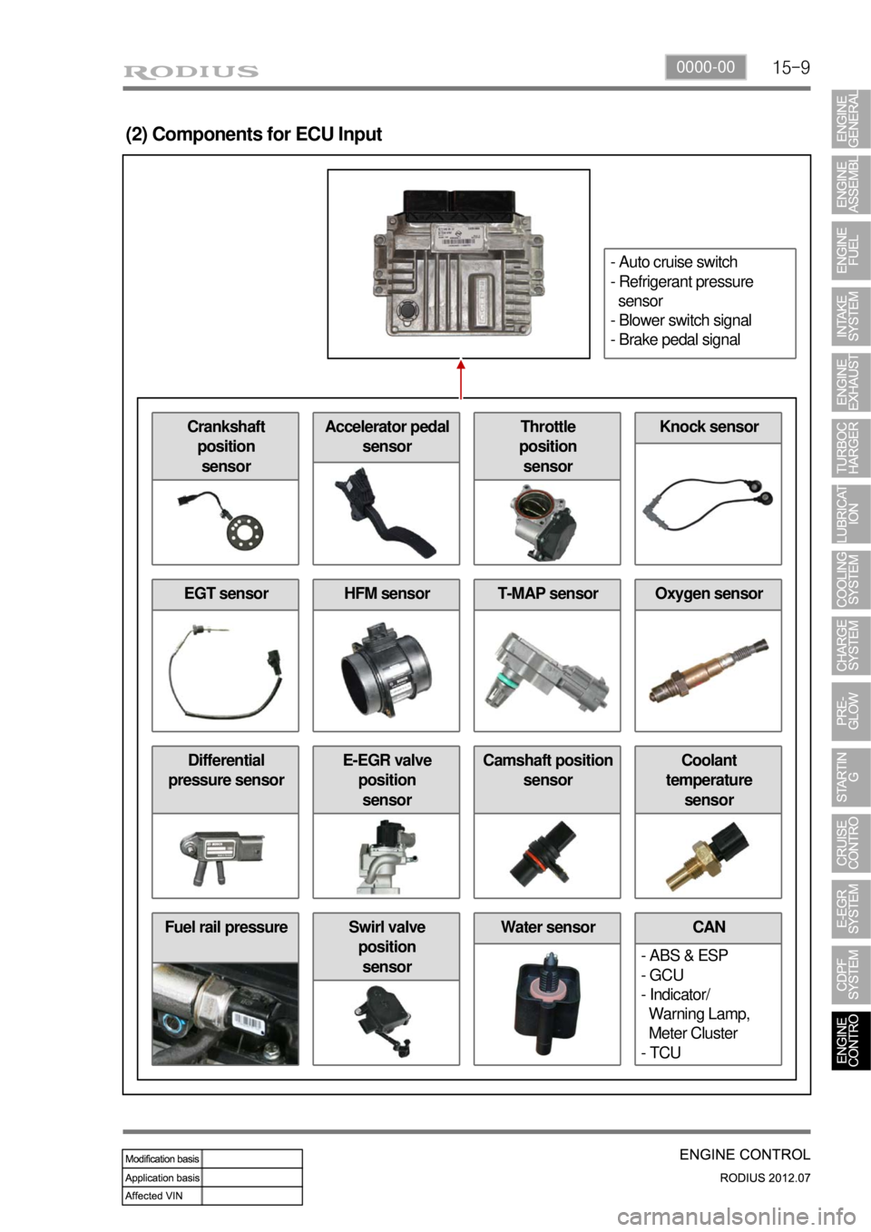
Fuel rail pressure Water sensor
(2) Components for ECU Input
CAN
- ABS & ESP
- GCU
- Indicator/
Warning Lamp,
Meter Cluster
- TCUSwirl valve
position
sensor
Differential
pressure sensorE-EGR valve
position
sensorCamshaft position
sensorCoolant
temperature
sensor
EGT sensorHFM sensorOxygen sensorT-MAP sensor
Crankshaft
position
sensorAccelerator pedal
sensorThrottle
position
sensorKnock sensor
- Auto cruise switch
- Refrigerant pressure
sensor
- Blower switch signal
- Brake pedal signal
Page 335 of 715

15-10
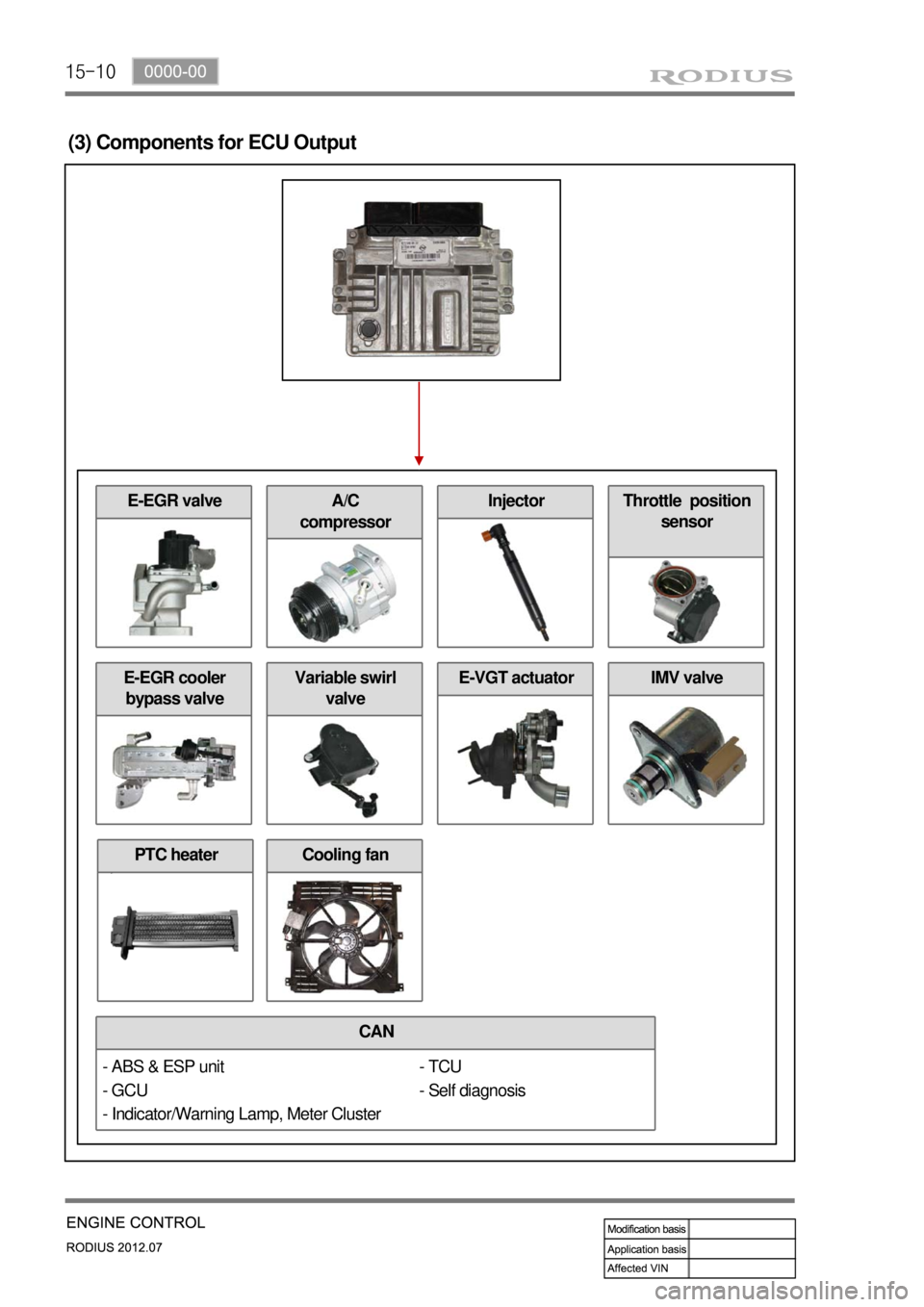
(3) Components for ECU Output
CAN
E-EGR cooler
bypass valve
- TCU
- Self diagnosis
Cooling fan
E-EGR valve
Variable swirl
valveE-VGT actuatorIMV valve
A/C
compressorInjectorThrottle position
sensor
- ABS & ESP unit
- GCU
- Indicator/Warning Lamp, Meter Cluster
PTC heater
Page 336 of 715

15-110000-00
2) ECU Control
(1) Function
a. ECU Function
ECU receives and analyzes signals from various sensors and then modifies those signals into
permissible voltage levels and analyzes to control respective actuators.
ECU microprocessor calculates injection period and injection timing proper for engine piston speed and
crankshaft angle based on input data and stored specific map to control the engine power and emission
gas.
Output signal of the ECU microprocessor drives pressure control valve to control the rail pressure and
activates injector solenoid valve to control the fuel injection period and injection timing; so controls
various actuators in response to engine changes. Auxiliary function of ECU has adopted to reduce
emission gas, improve fuel economy and enhance safety, comforts and conveniences. For example,
there are EGR, booster pressure control, autocruise (export only) and immobilizer and adopted CAN
communication to exchange data among electrical systems (automatic T/M and brake system) in the
vehicle fluently. And Scanner can be used to diagnose vehicle status and defectives.
<00760097008c00990088009b00900095008e0047009b008c00940097008c00990088009b009c0099008c0047009900880095008e008c00470096008d0047006c006a007c00470090009a0047009500960099009400880093009300a000470054005b005700
47009b009600470052005f005c00b6006a004700880095008b> protected from factors like oil,
water and electromagnetism and there should be no mechanical shocks.
To control the fuel volume precisely under repeated injections, high current should be applied instantly
so there is injector drive circuit in the ECU to generate necessary current during injector drive stages.
Current control circuit divides current applying time (injection time) into full-in-current-phase and hold-
current-phase and then the injectors should work very correctly under every working condition.
b. Control Function
Controls by operating stages
To make optimum combustion under every operating stage, ECU should calculate proper injection
volume in each stage by considering various factors.
Starting injection volume control
During initial starting, injecting fuel volume will be calculated by function of temperature and engine
cranking speed. Starting injection continues from when the ignition switch is turned to ignition
position to till the engine reaches to allowable minimum speed.
Driving mode control
If the vehicle runs normally, fuel injection volume will be calculated by accelerator pedal travel and
engine rpm and the drive map will be used to match the drivers inputs with optimum engine power. -
-
-
Page 343 of 715

15-18
C. Idle Speed Controller
The idle speed controller consists of 2 principal modules:
The first module determines the required idle speed according to:
* The operating conditions of the engine (coolant temperature, gear engaged)
* Any activation of the electrical consumers (power steering, air conditioning, others)
* The battery voltage
* The presence of any faults liable to interface with the rail pressure control or the injection control. In
this case, increase the idle speed to prevent the engine from stalling.
The second module is responsible for providing closed loop control of the engine's idle speed by
adapting the minimum fuel according to the difference between the required idle speed and the
engine speed. -
-
D. Flow Limitation
The flow limitation strategy is based on the following strategies:
The flow limitation depending on the filling of the engine with air is determined according to the
engine speed and the air flow. This limitation allows smoke emissions to be reduced during
stabilized running.
The flow limitation depending on the atmospheric pressure is determined according to the engine
speed and the atmospheric pressure. It allows smoke emissions to be reduced when driving at
altitude.
The full load flow curve is determined according to the gear engaged and the engine speed. It
allows the maximum torque delivered by the engine to be limited.
A performance limitation is introduced if faults liable to upset the rail pressure control or the
injection control are detected by the system. In this case, and depending on the gravity of the fault,
the system activates: -
-
-
-
Reduced fuel logic 1: Guarantees 75 % of the performance without limiting the engine speed.
Reduced fuel logic 2: Guarantees 50 % of the performance with the engine speed limited to
3,000 rpm.
Reduce fuel logic 3: Limits the engine speed to 2,000 rpm.
The system chooses the lowest of all values.
A correction depending on the coolant temperature is added to the flow limitation. This correction makes
it possible to reduce the mechanical stresses while the engine is warming up.
The correction is determined according to the coolant temperature, the engine speed and the time which
has passed since starting.
E. Superchager Flow Demand
The supercharge flow is calculated according to the engine speed and the coolant temperature. A
correction depending on the air temperature and the atmospheric pressure is made in order to increase
the supercharge flow during cold starts. It is possible to alter the supercharge flow value by adding a flow
offset with the aid of the diagnostic tool