cooling SSANGYONG RODIUS 2012 User Guide
[x] Cancel search | Manufacturer: SSANGYONG, Model Year: 2012, Model line: RODIUS, Model: SSANGYONG RODIUS 2012Pages: 715, PDF Size: 79.36 MB
Page 308 of 715

13-31793-00
1. SPECIFICATION
Item Specification
E-EGR valve Motor EGR response time 50 ms
Driven by DC motor
Valve EGR gas flow rate 120 Kg/h
Position sensor Sensing type Hole sensor
Supplied voltage5V ± 10%
Maximum signal
range5% ~ 95%
Maximum power
consumption<15mA
E-EGR cooler Cooling capacity 8.3 kW or more
Cooling fin type Wavy fin
Cooler type U-shaped
E-EGR bypass valve Driven by Vacuum
(Solenoid valve)
Page 335 of 715

15-10
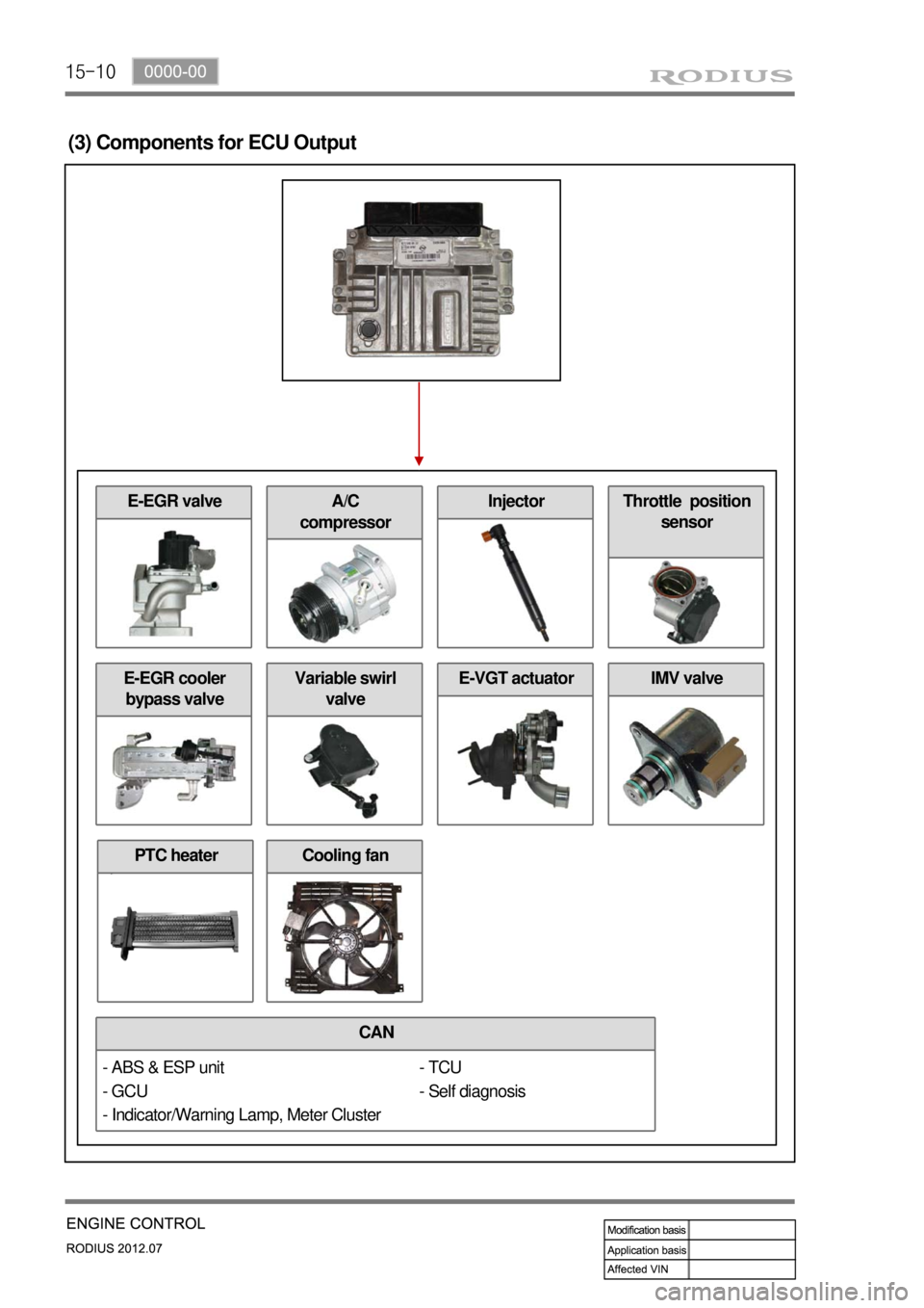
(3) Components for ECU Output
CAN
E-EGR cooler
bypass valve
- TCU
- Self diagnosis
Cooling fan
E-EGR valve
Variable swirl
valveE-VGT actuatorIMV valve
A/C
compressorInjectorThrottle position
sensor
- ABS & ESP unit
- GCU
- Indicator/Warning Lamp, Meter Cluster
PTC heater
Page 363 of 715

15-38
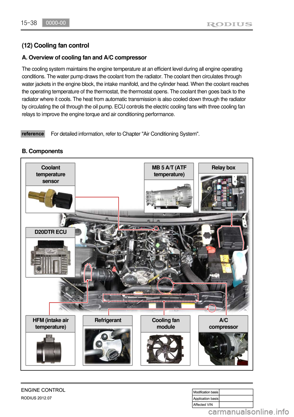
Relay box
A/C
compressorHFM (intake air
temperature)Cooling fan
module
MB 5 A/T (ATF
temperature)Coolant
temperature
sensor
(12) Cooling fan control
A. Overview of cooling fan and A/C compressor
The cooling system maintains the engine temperature at an efficient level during all engine operating
conditions. The water pump draws the coolant from the radiator. The coolant then circulates through
water jackets in the engine block, the intake manifold, and the cylinder head. When the coolant reaches
the operating temperature of the thermostat, the thermostat opens. The coolant then goes back to the
radiator where it cools. The heat from automatic transmission is also cooled down through the radiator
by circulating the oil through the oil pump. ECU controls the electric cooling fans with three cooling fan
relays to improve the engine torque and air conditioning performance.
For detailed information, refer to Chapter "Air Conditioning System".
B. Components
D20DTR ECU
Refrigerant
Page 364 of 715

15-390000-00
C. Input/Output for cooling fan and A/C compressor
Page 365 of 715

15-40
D. Cooling fan and A/C compressor control
Conditions for cooling fan control ▶
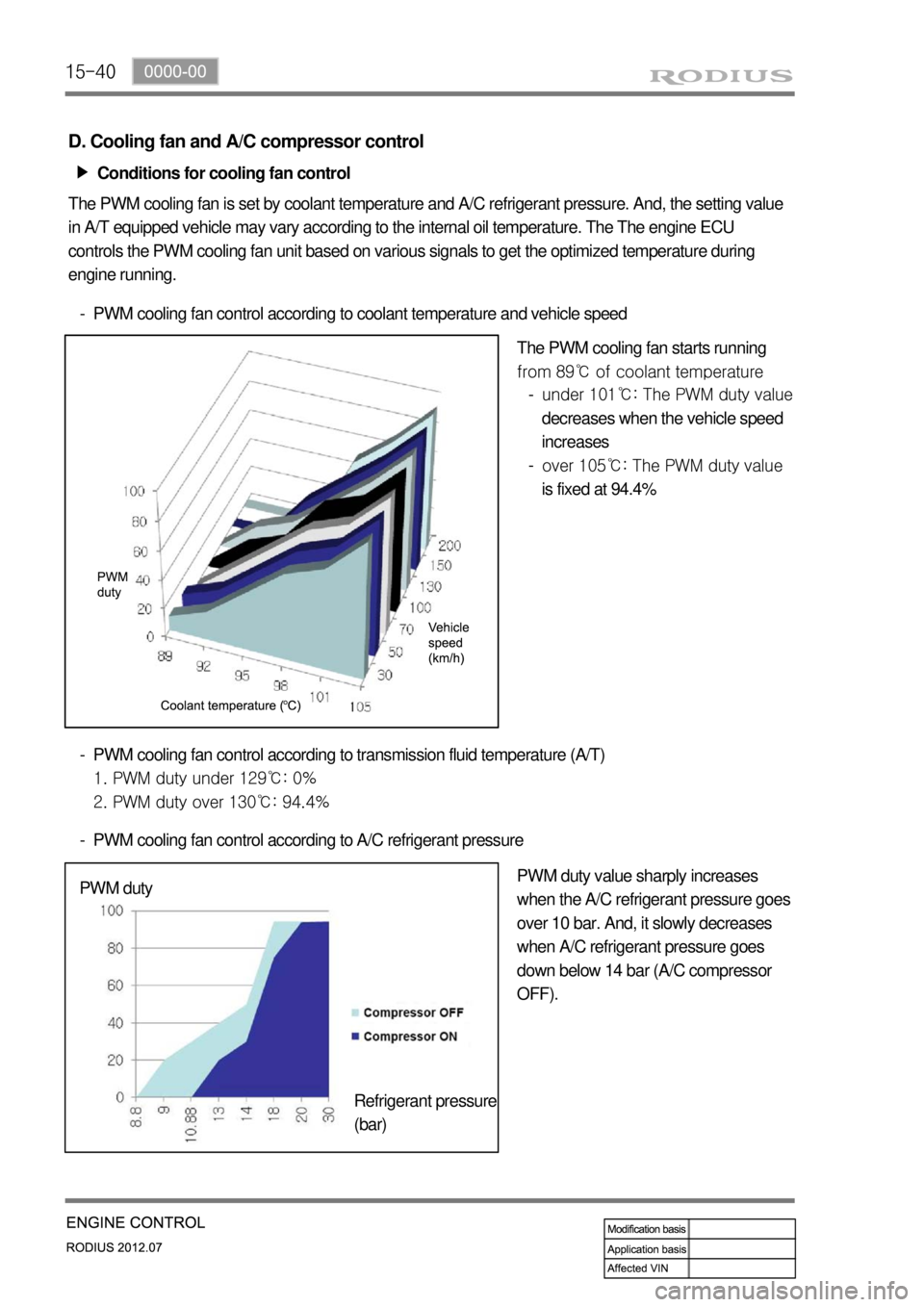
The PWM cooling fan is set by coolant temperature and A/C refrigerant pressure. And, the setting value
in A/T equipped vehicle may vary according to the internal oil temperature. The The engine ECU
controls the PWM cooling fan unit based on various signals to get the optimized temperature during
engine running.
PWM cooling fan control according to coolant temperature and vehicle speed -
The PWM cooling fan starts running
from 89℃ of coolant temperature
PWM cooling fan control according to transmission fluid temperature (A/T)
1. PWM duty under 129℃: 0%
2. PWM duty over 130℃: 94.4% -
PWM cooling fan control according to A/C refrigerant pressure -
PWM duty value sharply increases
when the A/C refrigerant pressure goes
over 10 bar. And, it slowly decreases
when A/C refrigerant pressure goes
down below 14 bar (A/C compressor
OFF). PWM duty
Refrigerant pressure
(bar)under 101℃: The PWM duty value
decreases when the vehicle speed
increases
over 105℃: The PWM duty value
is fixed at 94.4% -
-
Page 366 of 715

15-410000-00
A/C compressor OFF conditions ▶
Coolant temperature: below -20℃ or over
115℃
Engine rpm: over 4500 rpm
Engine rpm: below 600 rpm
When abrupt acceleration
Very high load during idling
Refrigerant pressure: over 32 bar or below 2
bar
Failure in refrigerant sensor, coolant
temperature sensor, and cooling fan -
-
-
-
-
-
-
Page 378 of 715

01-6
2) Side View
NO. FUNCTION NO. FUNCTION
23 Camshaft adjuster 27 Oil pump drive chain
24 Cooling fan and viscous clutch 28 Oil return pipe
25 Piston 29 Timing chain
26 Flywheel of drive plate
Page 397 of 715

07-6
1. GENERAL DESCRIPTION
The cooling system maintains the engine temperature at an efficient level during all engine
operating conditions. When the engine is cold, the cooling system cools the engine slowly or not
at all. This slow cooling of the engine allows the engine to warm up quickly. The cooling system
includes a radiator and recovery subsystem, cooling fans, a thermostat and housing, a water
pump, and a water pump drive belt. The timing belt drives the water pump. All components must
function properly for the cooling system to operation. The water pump draws the coolant from the
radiator.
The coolant then circulates through water jackets in the engine block, the intake manifold, and
the cylinder head. When the coolant reaches the operating temperature of the thermostat, the
thermostat opens. The coolant then goes back to the radiator where it cools. This system directs
some coolant through the hoses to the heat core. This provides for heating and defrosting. The
coolant reservoir is connected to the radiator to recover the coolant displaced by expansion from
the high temperatures. The coolant reservoir maintains the correct coolant level. The cooling
system for this vehicle has no radiator cap or filler neck. The coolant is added to the cooling
system through the coolant reservoir.
Page 399 of 715

07-8
Radiator
Electric fan
Shroud
Deaeration tube
Clamp
Deaeration hose (radiator)
Electric fan mounting bracket
Bolt (M6, 8 pieces)
Bolt (M6, 4 pieces)
Bolt (M6, 4 pieces)
Upper radiator insulator
Lower radiator insulator
Plate
Clip 1.
2.
3.
4.
5.
6.
7.
8.
9.
10.
11.
12.
13.
14.Inlet hose
Outlet hose
3 way hose
Deaeration hose (reserver tank)
Clamp
Clamp
Make up hose holder
Reserver tank
Bolt (M6, 2 piece)
Cooling fan
Viscous clutch
Bolt (M6, 1 piece)
Bolt (M6, 3 piece) 15.
16.
17.
18.
19.
20.
21.
22.
23.
24.
25.
26.
27.
Page 663 of 715

01-8
2. SYSTEM BLOCK DIAGRAM
A/C compressor OFF conditions ▶
Coolant temperature: over 115℃
Engine speed: over 4,500 rpm for more than 2 seconds
Engine speed: below 650 rpm
Maximum output due to abrupt acceleration
Excessive acceleration
Increased load during engine idling (to prevent the engine from shutting off)
Refrigerant pressure: over 32 bar or below 2 bar
Defects in A/C related system (refrigerant pressure sensor, coolant temperature sensor,
cooling fan) 1.
2.
3.
4.
5.
6.
7.
8.