wiring SSANGYONG RODIUS 2012 User Guide
[x] Cancel search | Manufacturer: SSANGYONG, Model Year: 2012, Model line: RODIUS, Model: SSANGYONG RODIUS 2012Pages: 715, PDF Size: 79.36 MB
Page 402 of 715

08-51452-01
1. CHARGING SYSTEM OPERATION
Alternators use a new type of regulator that incorpo-rates a diode trio. A Delta stator, a rectifier
bridge, and a rotor with slip rings and brushes are electrically similar to earlier alternators.
A conventional pulley and fan are used. There is no test hole.
1) Charging Time Required
The time required to charge a battery will vary depending upon the following factors:
Size of Battery ▶
A Completely discharged large heavy-duty battery required more than twice the
recharging time as a completely discharged small passenger car battery. -
Temperature ▶
A longer time will be needed to charge any battery at -18°C (0°F) than at 27°C (80°F).
When a fast charger is connected to a cold battery, the current accepted by the battery
will be very low at first. The battery will accept a higher current rate as the battery warms. -
Charger Capacity ▶
A charger which can supply only 5 amperes will require a much longer charging period
than a charger that can supply 30 amperes or more. -
State-of-Charge ▶
A completely discharged battery requires more than twice as much charge as a onehalf
charged battery. Because the electrolyte is nearly pure water and a poor conductor in a
completely discharged battery, the current accepted by the battery is very low at first.
Later, as the charging current causes the electrolyte acid content to increase, the charging
current will likewise increase. -
2. STARTING SYSTEM OPERATION
The engine electrical system includes the battery, the ignition, the starter, the alternator, and all
the related wiring. Diagnostic tables will aid in troubleshooting system faults. When a fault is
traced to a particular component, refer to that component section of the service manual. The
starting system circuit consists of the battery, the starter motor, the ignition switch, and all the
related electrical wiring. All of these components are connected electrically.
Page 418 of 715

01-4
Make sure a connector is connected
securely. Loose connection results in
malfunction. -
When inspecting the airbag system, make
sure to use a diagnostic device, not a
circuit tester.When disconnecting a connector equipped
with a lock, press it down to the direction in
the below figure. -
When checking voltage or continuity of the
connector terminal with a circuit tester,
connect the tester probe to the terminal at
the harness side. For a sealed type
connector, connect the probe to the
terminal through the hole in the rubber cap
of the wiring. Take care not to damage the
insulation of the wires. Insert the probe until
it contacts the terminal completely. -
Page 419 of 715

01-58410-02
2. CHECKING CABLES AND WIRES
Check for loose connection or rust.
Check terminals and wires for corrosion due to electrolyte leakage.
Check terminals and wires for open circuit.
Check the wire insulation and coat for damage, cracks or deterioration.
Check if the conductive parts of the terminals do not contact with vehicle body or other metal
parts.
Check that the grounding part has continuity with mounting bolts and vehicle body.
Check that wires are properly routed.
Make sure that wires are securely fixed to avoid contact with sharp body parts and
hightemperature
parts, such as the exhaust manifold and exhaust pipes.
The rotating parts, such as fan pulley and fan belt, perturbative parts and wiring should be
secured tightly at regular intervals.
Secure the wiring between the fixed parts, such as the vehicle body, and vibrating parts, such
as the engine, after slackening it slightly to prevent it from being damaged. -
-
-
-
-
-
-
-
-
Page 552 of 715

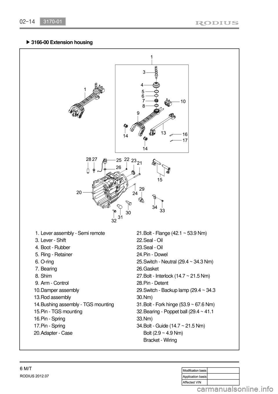
02-14
3166-00 Extension housing ▶
Lever assembly - Semi remote
Lever - Shift
Boot - Rubber
Ring - Retainer
O-ring
Bearing
Shim
Arm - Control
Damper assembly
Rod assembly
Bushing assembly - TGS mounting
Pin - TGS mounting
Pin - Spring
Pin - Spring
Adapter - Case 1.
3.
4.
5.
6.
7.
8.
9.
10.
13.
14.
15.
16.
17.
20.Bolt - Flange (42.1 ~ 53.9 Nm)
Seal - Oil
Seal - Oil
Pin - Dowel
Switch - Neutral (29.4 ~ 34.3 Nm)
Gasket
Bolt - Interlock (14.7 ~ 21.5 Nm)
Pin - Detent
Switch - Backup lamp (29.4 ~ 34.3
Nm)
Bolt - Fork hinge (53.9 ~ 67.6 Nm)
Bearing - Poppet ball (29.4 ~ 41.1
Nm)
Bolt - Guide (14.7 ~ 21.5 Nm)
Bolt (2.9 ~ 4.9 Nm)
Bracket - Wiring 21.
22.
23.
24.
25.
26.
27.
28.
29.
30.
31.
32.
33.
34.
Page 657 of 715

01-2
Front air conditioner module assembly - inside instrument panel
Compressor - engine rightAQS/Air source selection
switch
Sun load sensor - instrument
panel upper left
1. SYSTEM LAYOUT AND COMPONENTS
Type Air cindotioner controller
FATC
Manual air
conditioner
It change sun load coming through
front windshield into current to input to
FATC controller. *
Air mix door
actuator
PTC (If equipped)
Duct temperature
sensor
Mode door
actuator
Air conditioner wiring
Thermo AMP
Air source door
actuator
Air conditioner
filter
Bloewr motor
Blower high speed relayPower transistor
Page 661 of 715

01-6
2) AIR CONDITIONER MODULE WIRING AND LAYOUT
(1) Front Air Conditioner Module
Air source selection
door actuator
Air conditioner
filterEvaporator
Blower motor
Blower high
speed relay
Heater core
Wiring layout
Components
Page 662 of 715

01-76810-30
(2) Rear Air Conditioner Module
Roof air conditioner duct
Blower motor
Evaporator
Mixer door
Heater core
Air mixer door actuator
Rear floor
heater duct
Heater &
air conditioner
pipes
Wiring layout
Components
Page 675 of 715

02-78810-03
Do not put the seat cover on the front seatbacks. It may interfere with the side air bag inflation.
When sitting in the rear seat, do not hold onto the seatback of the front seat. If the side air bag
inflates, the occupant may get seriously injured.
Do not lean on the door. When the side air bag inflates, the occupant may get seriously injured.
Do not place any objects such as an umbrella or a bag between the side air bag and the door.
Do not place the part of your body near the side air bag. You may obstruct the side air bag or
get injured by the inflation impact.
Do not slam the front doors. It may lead to an unintended inflation of the side air bag.
Do not move your seat too close to the steering wheel or dashboard. If you lower your head,
the air bag can hit your head during inflation and can cause severe injury or even death.
Hold only the outer rim of the steering so that the air bag can inflate without any hindrances.
Do not place your face or chest near the steering wheel and dashboard. Also, do not allow
anyone to place their hands, leg or face on the dashboard. The air bag cannot work properly.
Do not hold and operate the steering wheel by crossing your arms. You could get seriously
injured when the air bag deploys.
When the air bag inflates, it makes a loud noise and smoke. However, the smoke is a non-
toxic nitrogen gas.
When the air bag is deployed, non-toxic gas will come out. This gas may cause skin, eyes or
nose irritation.
Wash it out with cold and clean water and consult the doctor if irritation continues.
When any repairs are needed for the steering wheel, or when an accident occurred without the
air bag deployment, have the air bag system checked by Ssangyong Dealer or Ssangyong
Authorized Service Operation.
The windshield glass may be broken when the passenger's air bag is deployed.
The air bag deployment can cause abrasion on your hands and face. -
-
-
-
-
-
-
-
-
-
-
-
-
-
-
-
4) Major Replacement Parts after Air Bag Deployment
In Case Of Front Air Bag Deployment ▶
Instrument panel, deployed air bag module, air bag unit, seat belt pre-tensioner, wirings
(including connectors), damaged trim and components
In Case Of Curtain Air Bag Deployment ▶
Deployed side bag, air bag unit, side air bag sensor, wirings (including connectors), damaged
trim and seat components