coolant SSANGYONG RODIUS 2012 Owner's Manual
[x] Cancel search | Manufacturer: SSANGYONG, Model Year: 2012, Model line: RODIUS, Model: SSANGYONG RODIUS 2012Pages: 715, PDF Size: 79.36 MB
Page 273 of 715

08-8
Coolant reservoir
Oil filter module
Thermostat
When the engine coolant
reaches 90℃, the thermostat
starts to open (fully open at
100℃) and lets the coolant
flow to the radiator to
maintain the engine
temperature.
Water pump
The water pump is driven by the engine drive belt and
supplies the coolant to each area of the engine.
1. SYSTEM DESCRIPTION
1) Overview
Water pump Impeller vaneSealing
Page 274 of 715

08-91520-00
Coolant temperature sensor
Measures the coolant
temperature and sends the
result to the engine ECU.
Electric fan
Circulates the fresh air forcibly to exchange
heat with the radiator core fin.
Radiator
Releases heat through fins and cools down the hot
coolant as the coolant passes through the tube of
the radiator core.
Page 287 of 715

10-4
1. OVERVIEW
The pre-heating system for D20DTR engine has the glow plug to the cylinder head (combustion
chamber), and improves the cold start performance and reduces the emission level.
The pre-heating resistor (air heater) is used to heat the intake air.
This enables the diesel fuel to be ignited in low temperature condition.
The ECU receives the information such as, engine rpm, coolant temperature, engine torque, etc.,
through CAN communication during pre-heating process; and the pre-heating control unit
controls the pre-heating, heating during cranking and post-heating by the PWM control.
Glow plug
Engine ECU (D20DTR)Glow indicator
Glow plug control unit
(GCU)
Page 290 of 715

10-71413-00
4) Operation
Glow plug is installed in the cylinder head. It enhances the cold starting performance and reduces
the exhaust gas during cold starting.
ECU receives the data (engine rpm, coolant temperature, vehicle speed) through CAN lines.
Based on the data, GCU controls the pre-glow, cranking and post-glow. It also checks the glow
plugs, and sends the result to ECU.
(1) Temperature/Current Properties of GCU
GCU increases the temperature of glow plug very rapidly (approx. 2 seconds up to
1000°C)
FETs (similar to transistor) for each cylinder are integrated in GCU. During the pre-
glow period, battery voltage is supplied to the glow plugs directly to heat them rapidly.
After getting the desired temperature by pre-glowing, the temperature is controlled by
duty ratio. Step 1:
Step 2 & 3:
Step 4:
This shows the supplying voltage and time by GCU in each step. The step 4 is the period to
keep the temperature. -Step 1: I1
Step 2: I2
Step 3: I3
Step 4: I4
Page 310 of 715

13-51793-00
EGR pipe
Transports the exhaust gas from the EGR
cooler and EGR bypass valve to the intake
duct.E-EGR valve
Receives the electric signal from the ECU to
control the valve.
E-EGR cooler and bypass valve
The cooler lowers the high temperature of the
exhaust gas and the bypass valve directly
supplies the exhaust gas to the intake duct
without passing through the EGR cooler to
reduce the emission of exhaust gas before
warming up the engine.HFM sensor
Used as a main map value to control the EGR.
The coolant temperature, engine rpm, engine
load, intake air temperature (HFM: decreased
at 60˚C or more), atmospheric pressure
(atmospheric pressure sensor: altitude
compensation) are used as auxiliary map
values.
2) Location and Components
See the section "Engine control" for E-EGR
valve control logic.EGR coolerEGR bypass
For details, see the section "Engine control". *
Page 312 of 715
13-71793-00
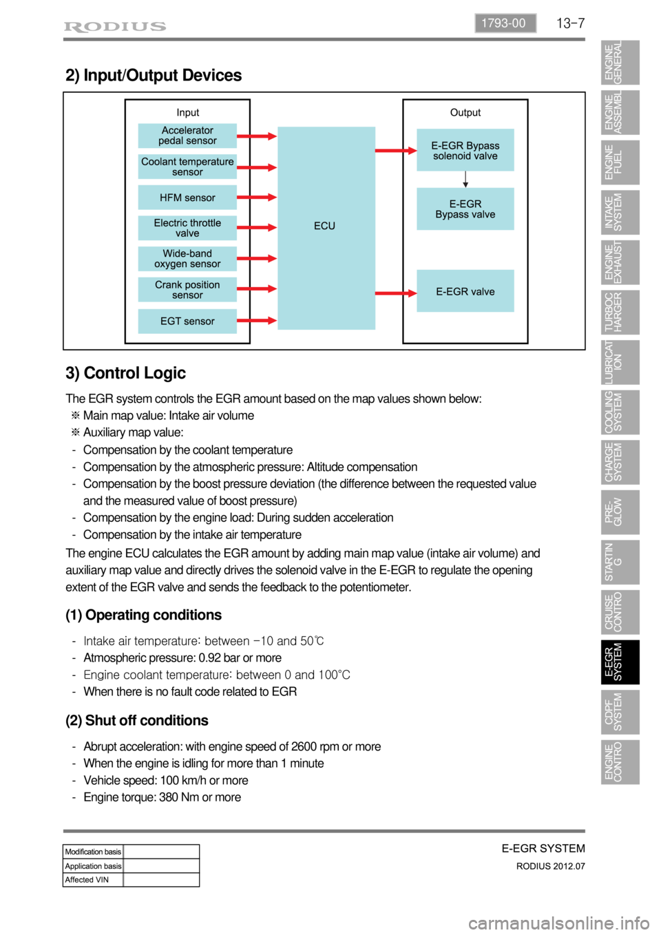
2) Input/Output Devices
3) Control Logic
The EGR system controls the EGR amount based on the map values shown below:
Main map value: Intake air volume
Auxiliary map value: ※
※
Compensation by the coolant temperature
Compensation by the atmospheric pressure: Altitude compensation
Compensation by the boost pressure deviation (the difference between the requested value
and the measured value of boost pressure)
Compensation by the engine load: During sudden acceleration
Compensation by the intake air temperature -
-
-
-
-
The engine ECU calculates the EGR amount by adding main map value (intake air volume) and
auxiliary map value and directly drives the solenoid valve in the E-EGR to regulate the opening
extent of the EGR valve and sends the feedback to the potentiometer.
(1) Operating conditions
Intake air temperature: between -10 and 50℃
Atmospheric pressure: 0.92 bar or more
Engine coolant temperature: between 0 and 100°C
When there is no fault code related to EGR -
-
-
-
(2) Shut off conditions
Abrupt acceleration: with engine speed of 2600 rpm or more
When the engine is idling for more than 1 minute
Vehicle speed: 100 km/h or more
Engine torque: 380 Nm or more -
-
-
-
Page 328 of 715
15-30000-00
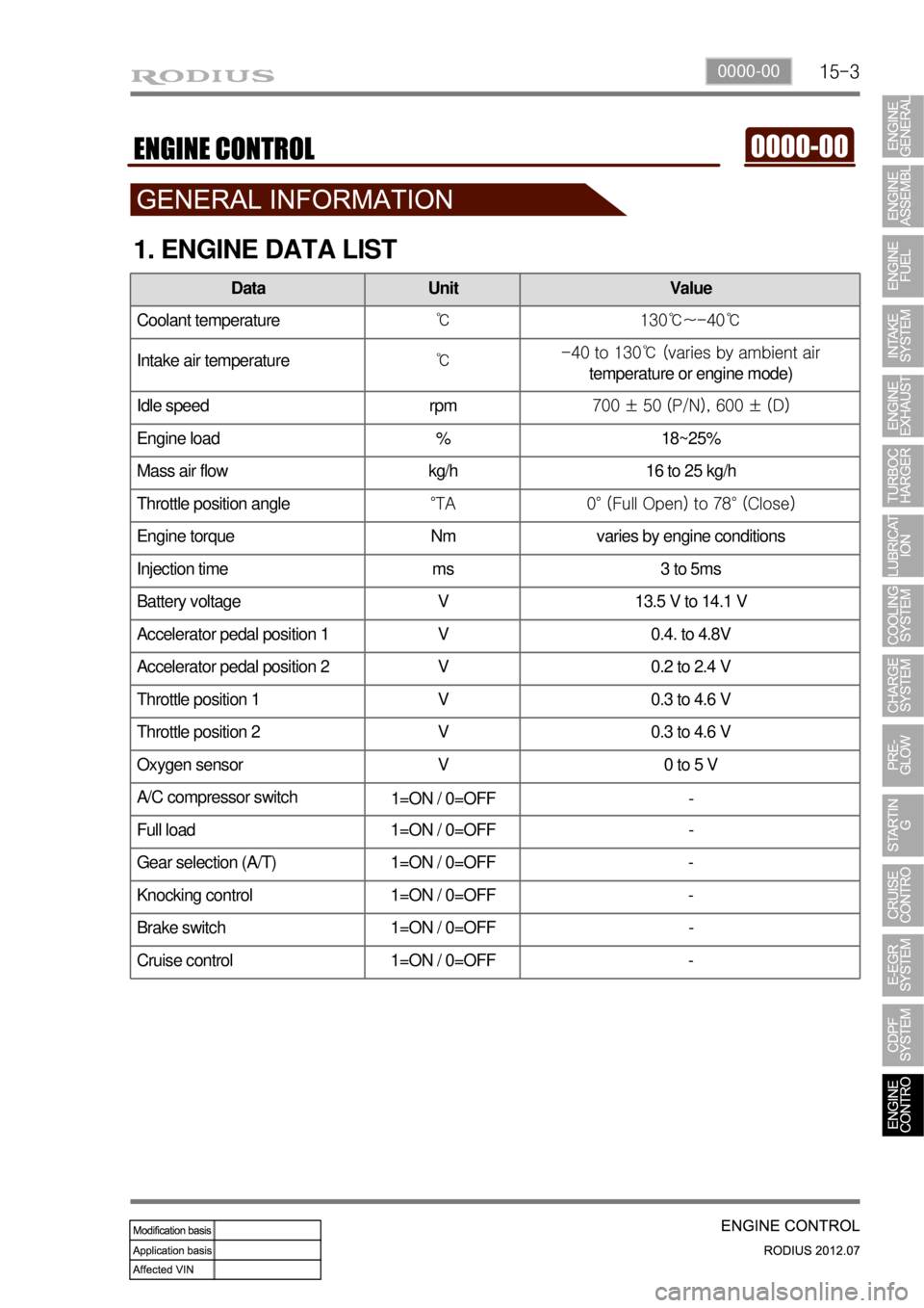
1. ENGINE DATA LIST
Data Unit Value
Coolant temperature℃ 130℃~-40℃
Intake air temperature℃ -40 to 130℃ (varies by ambient air
temperature or engine mode)
Idle speed rpm 700 ± 50 (P/N), 600 ± (D)
Engine load % 18~25%
Mass air flow kg/h 16 to 25 kg/h
Throttle position angle°TA 0° (Full Open) to 78° (Close)
Engine torque Nm varies by engine conditions
Injection time ms 3 to 5ms
Battery voltage V 13.5 V to 14.1 V
Accelerator pedal position 1 V 0.4. to 4.8V
Accelerator pedal position 2 V 0.2 to 2.4 V
Throttle position 1 V 0.3 to 4.6 V
Throttle position 2 V 0.3 to 4.6 V
Oxygen sensor V 0 to 5 V
A/C compressor switch
1=ON / 0=OFF -
Full load 1=ON / 0=OFF -
Gear selection (A/T) 1=ON / 0=OFF -
Knocking control 1=ON / 0=OFF -
Brake switch 1=ON / 0=OFF -
Cruise control 1=ON / 0=OFF -
Page 332 of 715
15-70000-00
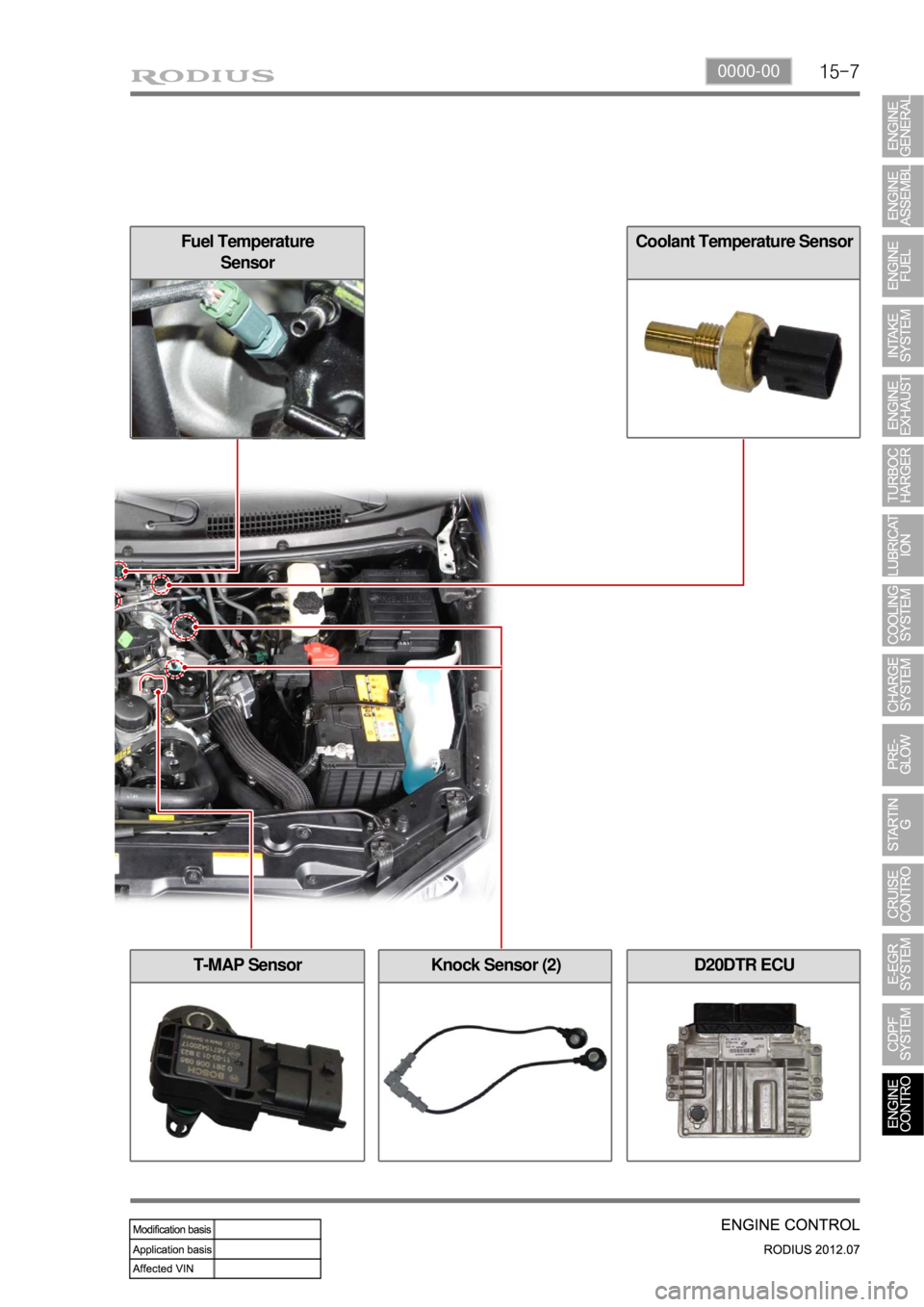
Fuel Temperature
SensorCoolant Temperature Sensor
Knock Sensor (2)T-MAP SensorD20DTR ECU
Page 334 of 715
15-90000-00
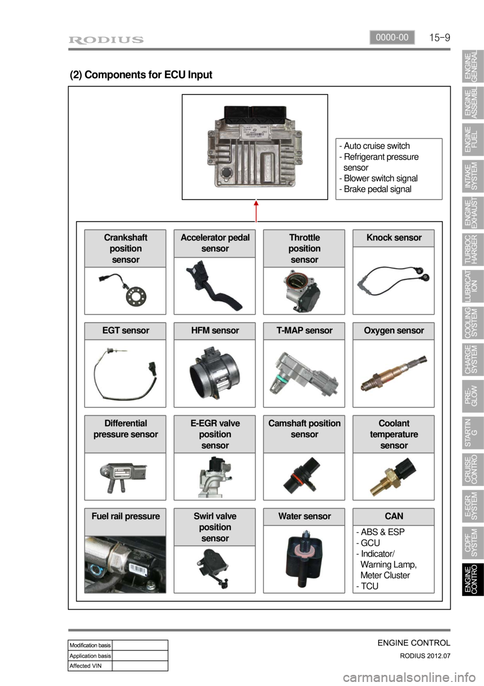
Fuel rail pressure Water sensor
(2) Components for ECU Input
CAN
- ABS & ESP
- GCU
- Indicator/
Warning Lamp,
Meter Cluster
- TCUSwirl valve
position
sensor
Differential
pressure sensorE-EGR valve
position
sensorCamshaft position
sensorCoolant
temperature
sensor
EGT sensorHFM sensorOxygen sensorT-MAP sensor
Crankshaft
position
sensorAccelerator pedal
sensorThrottle
position
sensorKnock sensor
- Auto cruise switch
- Refrigerant pressure
sensor
- Blower switch signal
- Brake pedal signal
Page 338 of 715
15-130000-00
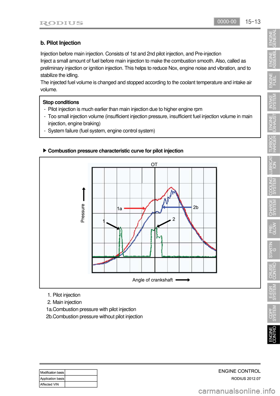
b. Pilot Injection
Injection before main injection. Consists of 1st and 2nd pilot injection, and Pre-injection
Inject a small amount of fuel before main injection to make the combustion smooth. Also, called as
preliminary injection or ignition injection. This helps to reduce Nox, engine noise and vibration, and to
stabilize the idling.
The injected fuel volume is changed and stopped according to the coolant temperature and intake air
volume.
Pilot injection is much earlier than main injection due to higher engine rpm
Too small injection volume (insufficient injection pressure, insufficient fuel injection volume in main
injection, engine braking)
System failure (fuel system, engine control system) -
-
-
Pilot injection
Main injection
Combustion pressure with pilot injection
Combustion pressure without pilot injection 1.
2.
1a.
2b. Stop conditions
Combustion pressure characteristic curve for pilot injection ▶