engine SSANGYONG RODIUS 2012 Workshop Manual
[x] Cancel search | Manufacturer: SSANGYONG, Model Year: 2012, Model line: RODIUS, Model: SSANGYONG RODIUS 2012Pages: 715, PDF Size: 79.36 MB
Page 208 of 715

03-4
Took kit for low pressure lineTool kit for high pressure line
2. MAINTENANCE AND INSPECTION
1) Maintenance Procedures for DI Engine Fuel System
Always keep the workshop and lift clean (especially, from dust).
Always keep the tools clean (from oil or foreign materials).
Wear a clean vinyl apron to prevent the fuzz, dust and foreign materials from getting into fuel
system. Wash your hands and do not wear working gloves. 1.
2.
3.
Follow the below procedures before starting service works for fuel system.
If the problem is from HP pump, fuel supply line or injector, prepare the clean special tools and
sealing caps to perform the diagnosis for DI engine fuel system in this manual. At this point,
thoroughly clean the related area in engine compartment. 4.
Clean the engine compartment before starting service works.
Page 209 of 715

03-52210-01
Plug the removed components with clean and undamaged sealing caps and store it into the
box to keep the conditions when it was installed. 6.
Fuel filter assembly
Follow the job procedures. If you find a defective component, replace it with new one. 5.
Once disconnected, the fuel pipes between HP pump and fuel rail and between fuel rail and each
injector should be replaced with new ones. The pipes should be tightened tospecified tightening
torques during installation. Over or under torques out of specified range may cause damages and
leaks at connections. Once installed, the pipes have been deformed according to the force
during installation, therefore they are not reusable. The copper washer on injector should be
replaced with new one. The injector holder bolt should be tightened to specified tightening torque
as well. If not, the injection point may be deviated from correct position, and it may cause engine
disorder.
To supply the fuel to transfer line of HP
pump press the priming pump until it
becomes hard. 7.
Priming pump
Check the installed components again and connect the negative battery cable. Start the engine
and check the operating status.
With Scan Tool, check if there are current faults and erase the history faults. 8.
9.
Priming pump cap
Page 210 of 715

03-6
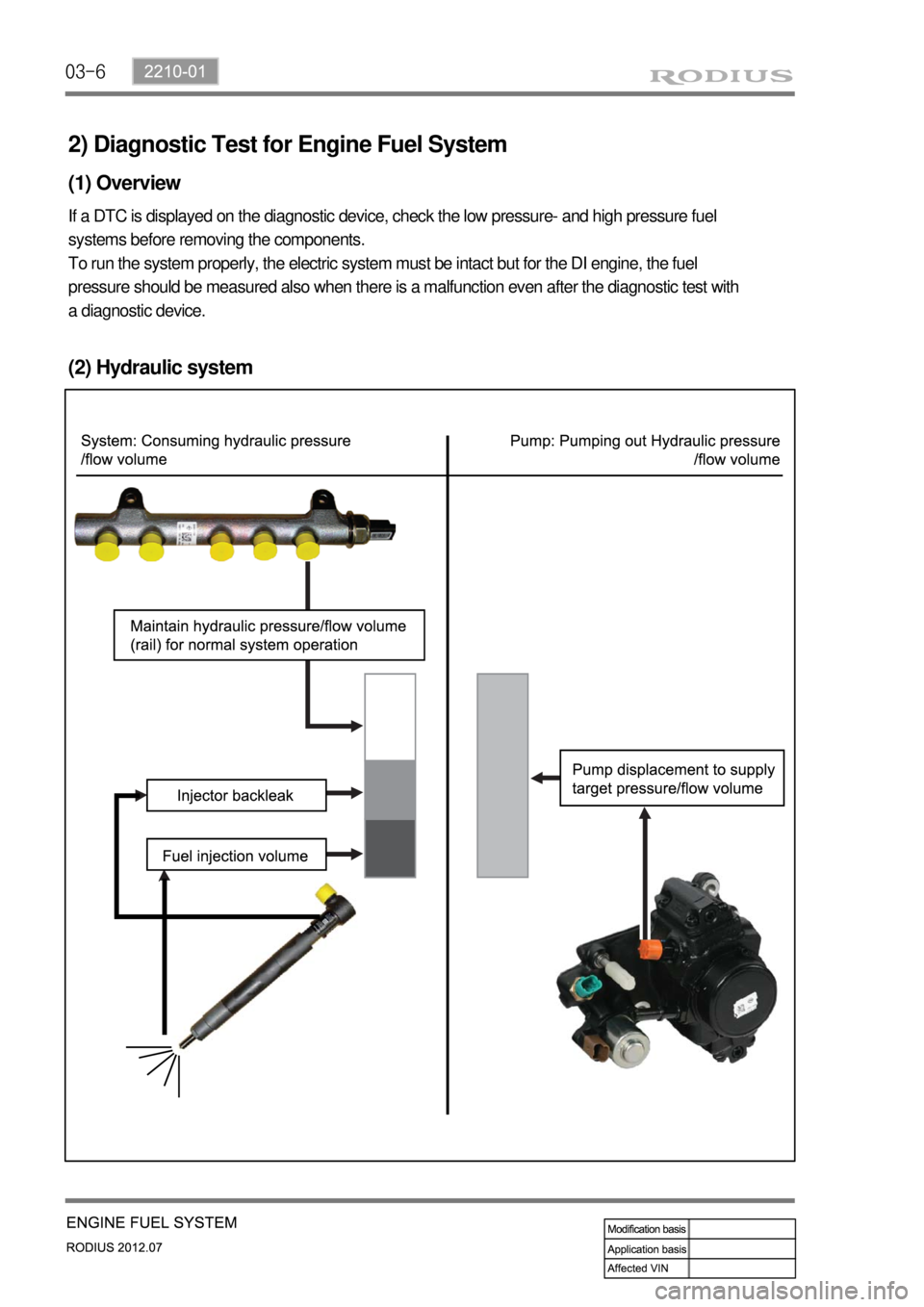
2) Diagnostic Test for Engine Fuel System
(1) Overview
If a DTC is displayed on the diagnostic device, check the low pressure- and high pressure fuel
systems before removing the components.
To run the system properly, the electric system must be intact but for the DI engine, the fuel
pressure should be measured also when there is a malfunction even after the diagnostic test with
a diagnostic device.
(2) Hydraulic system
Page 213 of 715

03-92210-01
Device for high pressure
Device for low pressure
3) DI Engine Fuel System Pressure Test
(1) Test device (Tool kit)
(2) Pre-check
Check-tighten fuel supply line
Check fuel level in fuel tank
Check air in fuel supply line (bubble in fuel supply line or fuel)
Check fuel supply line for leaks (low pressure and high pressure)
Check that specified fuel is used
Check fuel filter for contamination -
-
-
-
-
-
Page 214 of 715

03-10
(3) DI Engine Fuel System Check Procedure
If several DTCs are output simultaneously, check the electric wiring for open or short circuit.
Check the low pressure fuel system and fuel filter and confirm that there are no abnormalities.
Carry out the high pressure fuel system check.
Page 216 of 715

03-12
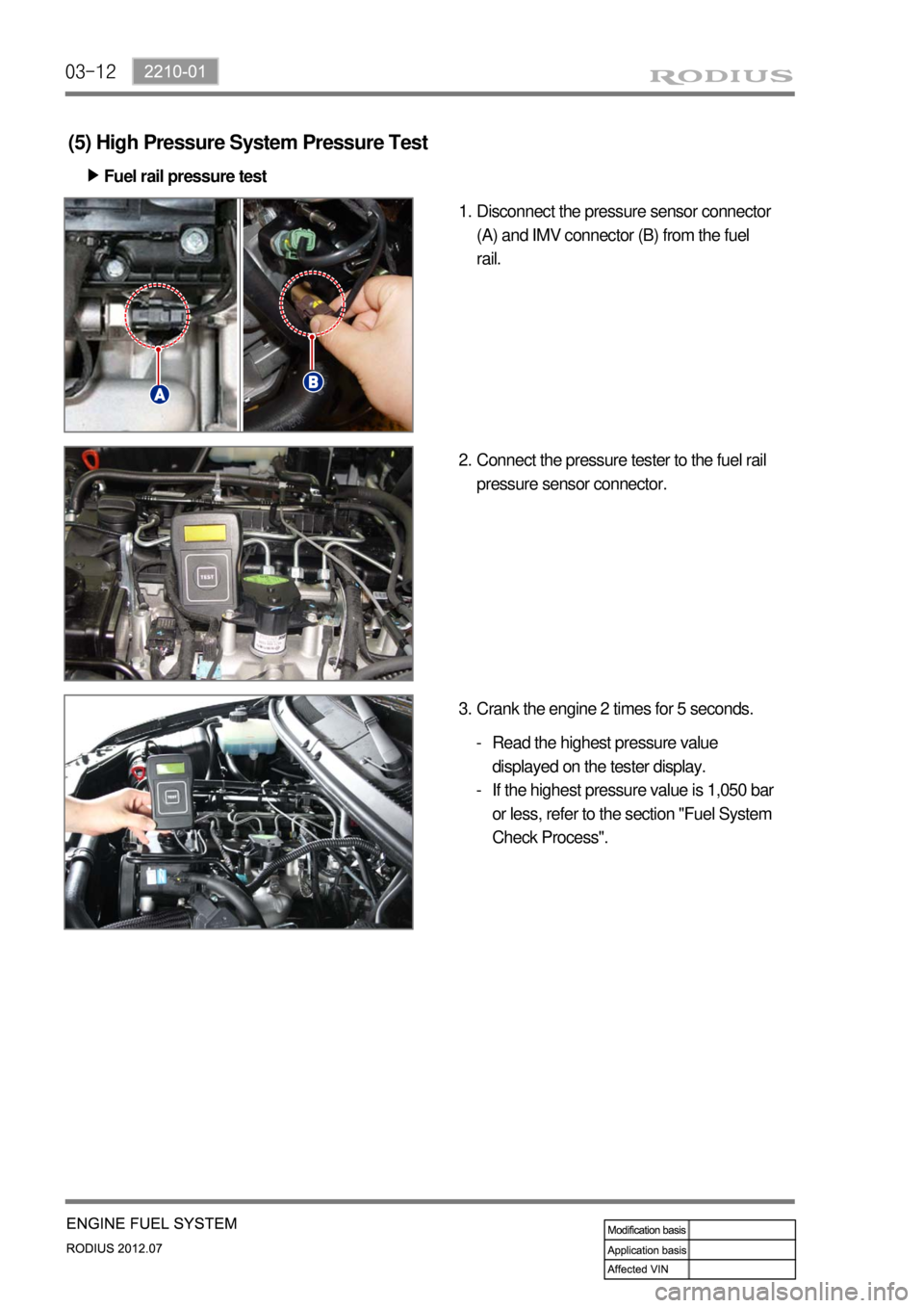
(5) High Pressure System Pressure Test
Fuel rail pressure test ▶
Disconnect the pressure sensor connector
(A) and IMV connector (B) from the fuel
rail. 1.
Connect the pressure tester to the fuel rail
pressure sensor connector. 2.
Crank the engine 2 times for 5 seconds. 3.
Read the highest pressure value
displayed on the tester display.
If the highest pressure value is 1,050 bar
or less, refer to the section "Fuel System
Check Process". -
-
Page 217 of 715

03-132210-01
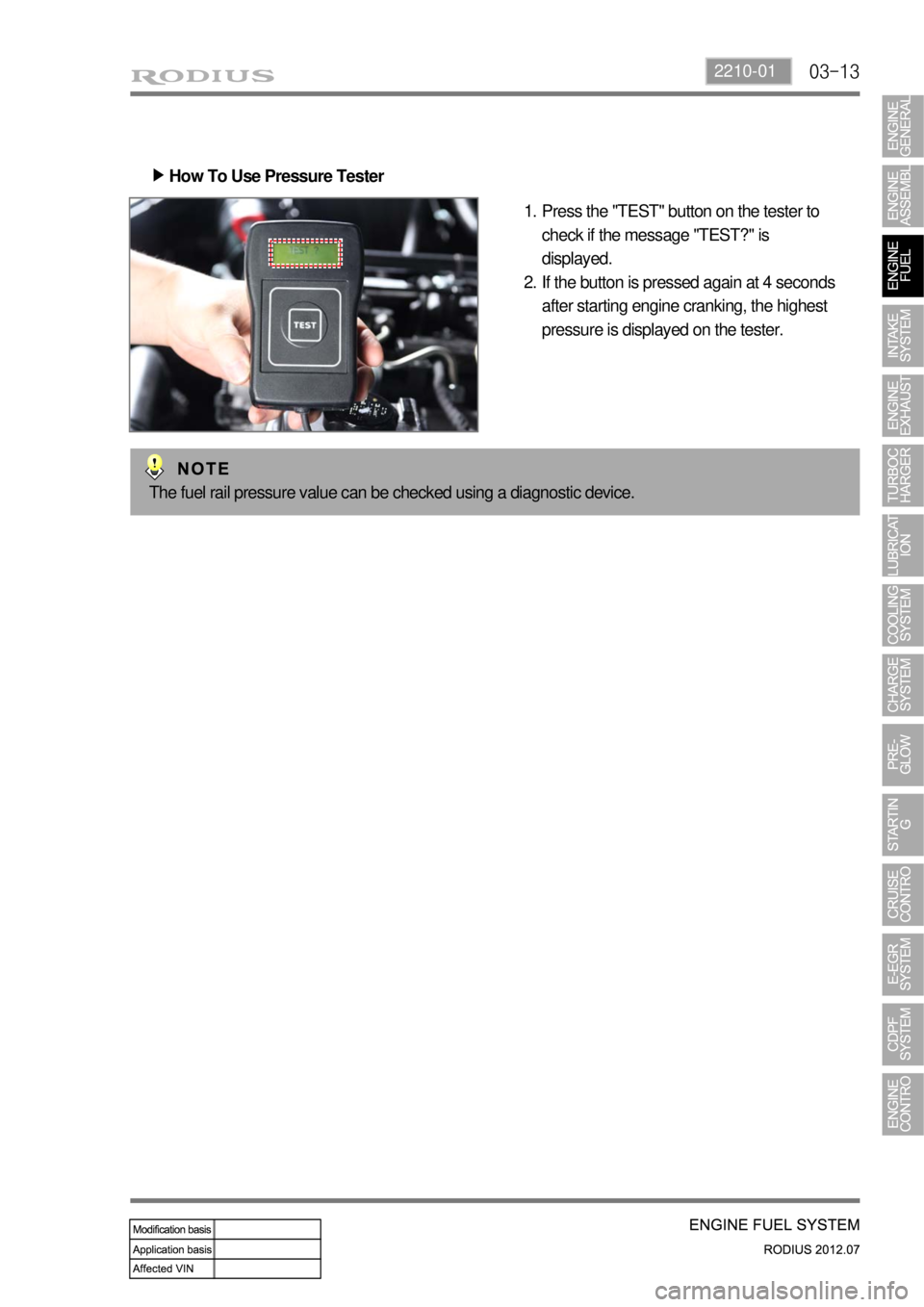
How To Use Pressure Tester ▶
Press the "TEST" button on the tester to
check if the message "TEST?" is
displayed.
If the button is pressed again at 4 seconds
after starting engine cranking, the highest
pressure is displayed on the tester. 1.
2.
The fuel rail pressure value can be checked using a diagnostic device.
Page 218 of 715

03-14
(6) Low Pressure System Pressure Test
Inspection procedure ▶
All wirings/connectors and fuel lines should
be connected and the engine should work
properly.
Prepare a special tool for low pressure test
and clean it thoroughly to prevent foreign
materials from entering. 1.
2.
Disconnect the key connector for fuel filter connection, and connect both connectors to the
fuel filter and hose. 3.
Start the engine and check visually for clogged low pressure fuel system, excessive air or air
entry.
If the fuel flow is not sufficient or air is in the fuel, repair the leak area. 4.
5.
Page 219 of 715

03-152210-01
Static test for backleak of injector ▶
Disconnect the injector return hose and
cover the openings with caps shaped
screw (included in the special tool). 1.
Connect the hose of the container for
measuring backleak to the return nipple of
the injector.
(prevent air entry to the low pressure line) 2.
Disconnect the IMV connector of the
high pressure pump and then fuel
pressure sensor connector. 3.
The connector of the injector can be easily
contaminated. Always keep it clean.
Crank the engine 2 times for 5 seconds.
Check the time for flow if injector backleak
and confirm that it is within the specified
range. 4.
5.
If the value is out of the specified range,
replace the injector.
SpecificationBelow 20 sec.
Page 220 of 715

03-16
Dynamic test for backleak of injector ▶
Warm up the engine so that the engine
coolant temperature be over 80℃ and star
the engine again.
Disconnect the injector return hose and
cover the openings with caps shaped
screw (included in the special tool). 1.
2.
Connect the hose of the container for
measuring backleak to the return nipple of
the injector.
Start the engine again and let the engine
idle for 30 seconds.
Perform backleak test of fuel system with a
diagnostic device after 30 seconds. 3.
4.
5.
This test consists of 4 cycles, and the engine
rpm reaches 3,500 rpm for 18 seconds in each
cycle.
Check the amount of backleak collected
into the container and confirm that it is
within the specified range. 6.
Specification38 ml or less