relay SSANGYONG RODIUS 2012 Service Manual
[x] Cancel search | Manufacturer: SSANGYONG, Model Year: 2012, Model line: RODIUS, Model: SSANGYONG RODIUS 2012Pages: 715, PDF Size: 79.36 MB
Page 148 of 715

01-6
3. ENGINE COMPARTMENT LAYOUT
Do not work on the engine compartment while the engine, radiator, exhaust manifold, muffler
or catalytic converter is hot. Always turn the engine off and allow it to cool before starting the
maintenance.
Regularly check the engine oil level and add Ssangyong genuine engine oil if necessary.
Clean the dipstick with clean cloth so that any foreign materials cannot get into the engine. -
-
-
Power steering fluid
reservoir Brake fluid reservoir
Engine oil
dipstick gauge
Washer fluid
reservoir cap Engine oil filler cap
Air cleaner
Operating vehicle with insuffi cient amount of oil can damage the engine. Make sure the
engine oil level is correct and add oil if necessary.
Coolant reservoir
Battery
Fuse & relay
Page 157 of 715

01-150000-00
7. CODING AND INITIALIZATION
1) Engine Variant Coding
Unit Selection Description
PTC auxiliary heater NO For PTC auxiliary heaterequipped
vehicle, select"YES".
YES
Glow plug Relay (K-line) Select "AQGS".
AQGS (CAN)
Transmission MT 5-speed Select the appropriate system.
MT 6-speed
AT 5-speed (DC 5AT)
AT 6-speed (DSI 6AT)
AT 7-speed (DC 7AT)
Pressure sensor
forA/C refrigerantNOSelect “Refrigerant pressure sensor”.
Refrigerant Pressure Sensor
Immobilizer NO Select "YES" if the vehicle has
immobilizer.
YES
Vehicle speed input
typeCAN Select "CAN" if the vehicle has ABS or
ESP
WIRE
Cooling fan Relay Select "PWM".
PWM
Auto cruise NO Select "YES" if the vehicle hascruise
control.
YES
Engine level control NO Select "NO".
YES
G-sensor NOABS: Select “NO”.
4WD ABS or ESP: Select “YES”.
YES
SMART key NO Select "NO".
YES
Page 363 of 715

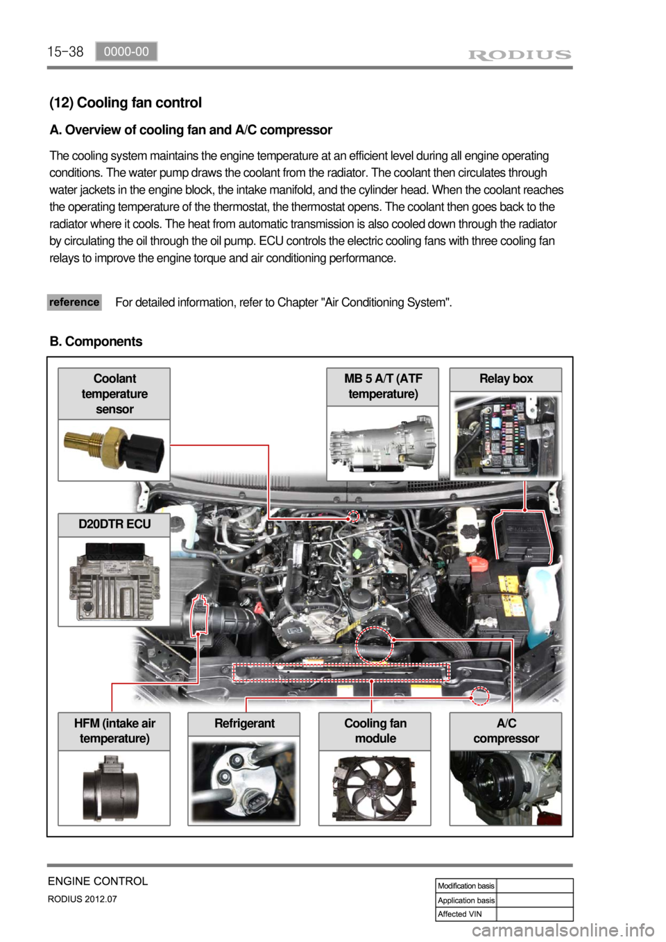
15-38
Relay box
A/C
compressorHFM (intake air
temperature)Cooling fan
module
MB 5 A/T (ATF
temperature)Coolant
temperature
sensor
(12) Cooling fan control
A. Overview of cooling fan and A/C compressor
The cooling system maintains the engine temperature at an efficient level during all engine operating
conditions. The water pump draws the coolant from the radiator. The coolant then circulates through
water jackets in the engine block, the intake manifold, and the cylinder head. When the coolant reaches
the operating temperature of the thermostat, the thermostat opens. The coolant then goes back to the
radiator where it cools. The heat from automatic transmission is also cooled down through the radiator
by circulating the oil through the oil pump. ECU controls the electric cooling fans with three cooling fan
relays to improve the engine torque and air conditioning performance.
For detailed information, refer to Chapter "Air Conditioning System".
B. Components
D20DTR ECU
Refrigerant
Page 367 of 715

15-42
(13) PTC heater control
A. Overview
The supplementary electrical heater is installed in DI engine equipped vehicle as a basic equipment. The
PTC system is operated according to two temperature values measured at the coolant temperature
sensor and HFM sensor. This device is mounted in the heater air outlet and increase the temperature of
air to the passenger compartment. Because PTC system is heated by electrical power, high capacity
alternator is required. PTC does not operate during engine cranking, while the battery voltage is lower
than 11 V or during preheating process of glow plugs.
B. Components
HFM (intake air
temperature)
Coolant temperature
sensor
PTC relay 1
D20DTR ECU
PTC relay 2
PTC fuse 1, 2, 3, 40A
PTC heater
PTC Fuse and Relay
Page 368 of 715

15-430000-00
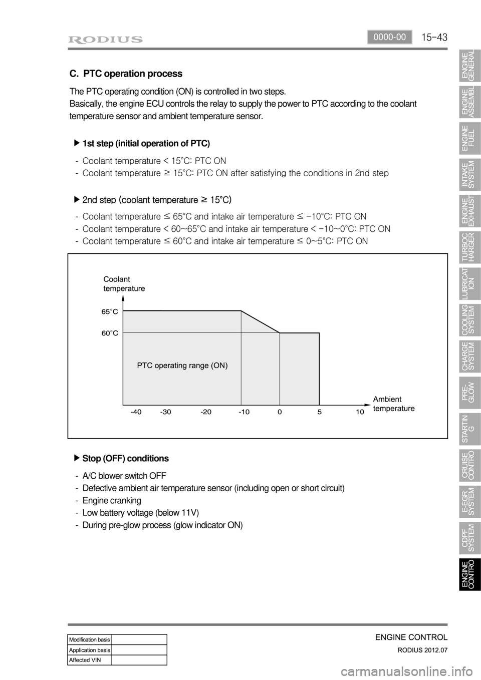
C. PTC operation process
The PTC operating condition (ON) is controlled in two steps.
Basically, the engine ECU controls the relay to supply the power to PTC according to the coolant
temperature sensor and ambient temperature sensor.
1st step (initial operation of PTC) ▶
Coolant temperature < 15°C: PTC ON
<006a00960096009300880095009b0047009b008c00940097008c00990088009b009c0099008c004702fb00470058005c00b6006a006100470077007b006a00470076007500470088008d009b008c00990047009a0088009b0090009a008d00a00090009500
8e0047009b008f008c0047008a00960095008b0090009b0090>ons in 2nd step -
-
2nd step (coolant temperature ≥ 15°C) ▶
<006a00960096009300880095009b0047009b008c00940097008c00990088009b009c0099008c004702fa0047005d005c00b6006a004700880095008b004700900095009b00880092008c00470088009000990047009b008c00940097008c00990088009b00
9c0099008c004702fa004700540058005700b6006a00610047>PTC ON
<006a00960096009300880095009b0047009b008c00940097008c00990088009b009c0099008c004700630047005d005700a5005d005c00b6006a004700880095008b004700900095009b00880092008c00470088009000990047009b008c00940097008c00
990088009b009c0099008c00470063004700540058005700a5>0°C: PTC ON
<006a00960096009300880095009b0047009b008c00940097008c00990088009b009c0099008c004702fa0047005d005700b6006a004700880095008b004700900095009b00880092008c00470088009000990047009b008c00940097008c00990088009b00
9c0099008c004702fa0047005700a5005c00b6006a00610047>PTC ON -
-
-
Stop (OFF) conditions ▶
A/C blower switch OFF
Defective ambient air temperature sensor (including open or short circuit)
Engine cranking
Low battery voltage (below 11V)
During pre-glow process (glow indicator ON) -
-
-
-
-
Page 417 of 715

01-38410-02
1. CAUTIONS WHEN WORKING ON ELECTRICAL UNITS
80℃
10A 15A
Disconnect the negative cable from the
battery in advance when working on
electrical units. -
Make sure to turn "OFF" the ignition switch
and other lamp switches before
disconnecting or connecting the negative
battery cable. (Otherwise, semiconductor
parts can be damaged.)
Do not drop or appy excessive impact to
sensors and relays. -
If a fuse is blown, replace it with a fuse
which has the correct amperage rating. If
you use a fuse with higher capacity than
the specification, the component can be
damaged or catch fire. -
Page 420 of 715

01-6
1. OVERVIEW
The fuse and relay boxes consist of four boxes: Fuse & relay box, in engine room and Fuse and
relay box in left side of instrument panel.
2. LOCATION
▶Engine Room Fuse and Relay Box
▶Interior Fuse and Relay Box
PTC Box Assembly
Page 421 of 715

01-78410-02
3. CIRCUIT DIAGRAM
▶SB1~SB4, C/FAN (HI,LO) REALY, F/HEATER RELAY, C/FAN (SUB) RELAY
1) Engine Room Fuse and Relay Box
Page 422 of 715

01-8
▶SB5~SB8, Ef5, Ef6, 2ND A/PUMP RELAY, ENG MAIN RELAY, START RELAY
Page 423 of 715

01-98410-02
▶SB9~SB11, Ef10, Ef23, RR BLOWER RELAY, DEFOGGER RELAY