coolant SSANGYONG TURISMO 2013 User Guide
[x] Cancel search | Manufacturer: SSANGYONG, Model Year: 2013, Model line: TURISMO, Model: SSANGYONG TURISMO 2013Pages: 796, PDF Size: 78.99 MB
Page 209 of 796

02-50
The bottom side of water jacket is desgined as sine wave to strengthen the structure of crankcase. The
main flow of coolant starts from outlet port of water pump and goes along the longitudinal direction of
engine. The coolant passage from cylinder head to inlet port of water pump is integrated in cylinder
head.
The engine oil from oil pump is supplied to the main oil gallery through oil channel, oil filter module and
cross bore in cylinder block without using external pipes. This oil is supplied to main bearing, cylinder
head and MBU. And, it is sprayed to the chain through the chain tensioner connected to cross bore.
Crankcase cross bore for oil supply
Water jacket core
Page 223 of 796
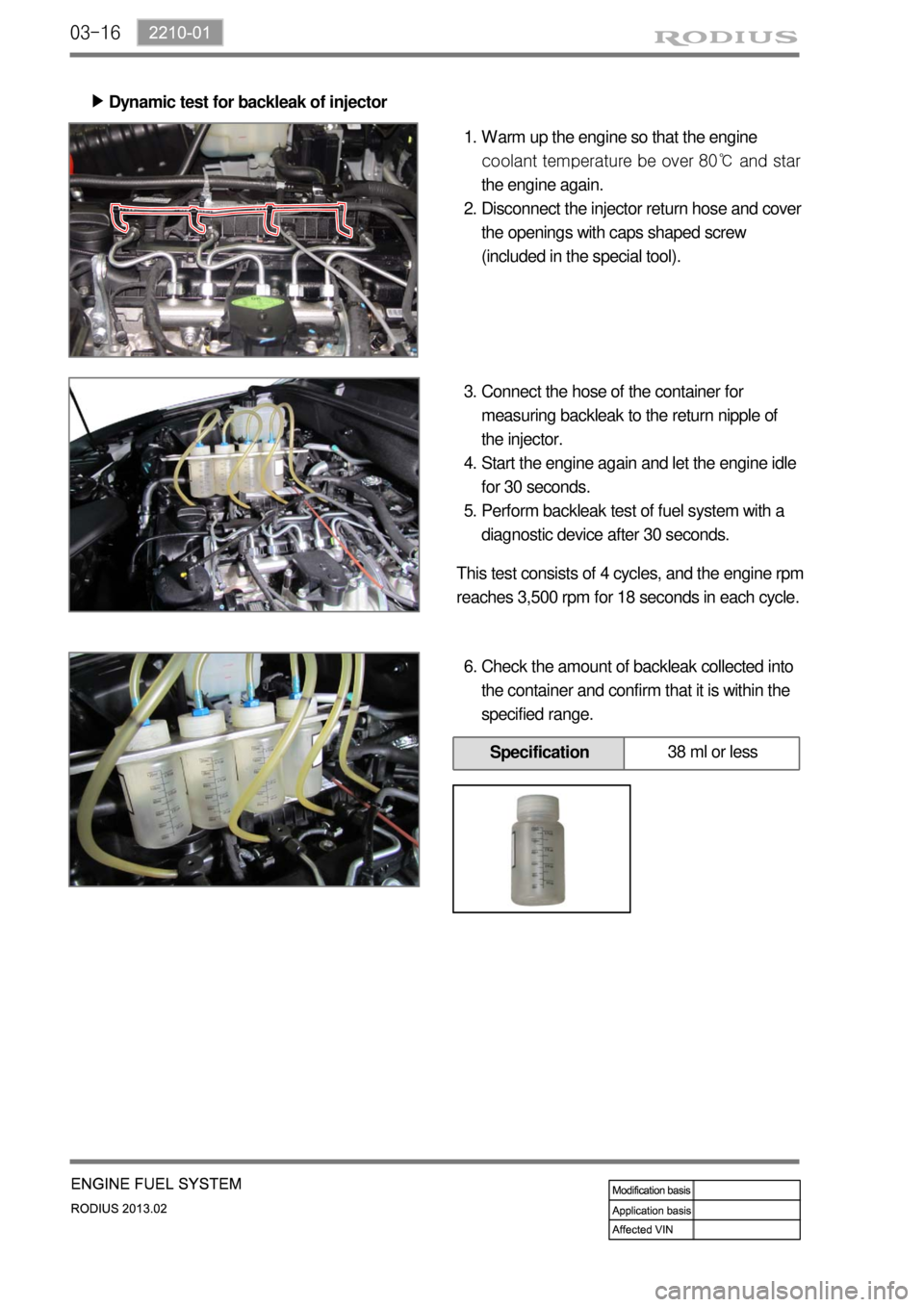
03-16
Dynamic test for backleak of injector ▶
Warm up the engine so that the engine
coolant tem
perature be over 80℃ and star
the engine again.
Disconnect the injector return hose and cover
the openings with caps shaped screw
(included in the special tool). 1.
2.
Connect the hose of the container for
measuring backleak to the return nipple of
the injector.
Start the engine again and let the engine idle
for 30 seconds.
Perform backleak test of fuel system with a
diagnostic device after 30 seconds. 3.
4.
5.
This test consists of 4 cycles, and the engine rpm
reaches 3,500 rpm for 18 seconds in each cycle.
Check the amount of backleak collected into
the container and confirm that it is within the
specified range. 6.
Specification38 ml or less
Page 233 of 796
03-26
The engine ECU calculates the accelerator pedal based on the input signals from various sensors, and
controls the overall operation of the vehicle.
The ECU receives the signals from various sensor through data line, and performs effective air-fuel ratio
control based on these signals.
The crankshaft speed (position) sensor measures the engine speed, and the camshaft speed (position)
sensor determines the order of injections, and the ECU detects the amount of the accelerator pedal
depressed (driver's will) by receiving the electrical signals from the accelerator pedal sensor.
The mass air flow sensor detects the volume of intake air and sends the value to the ECU.
The major function of the ECU is controlling air-fuel ratio to reduce the emission level (EGR valve
control) by detecting instantaneous air flow change with the signals from the mass air flow sensor.
Also, the ECU uses the signals from the coolant temperature & air temperature sensors, booster
pressure sensor, atmospheric pressure sensor to: a) determine injection starting point and set value for
pilot injection, and b) deal with various operations and variable conditions.
Page 264 of 796
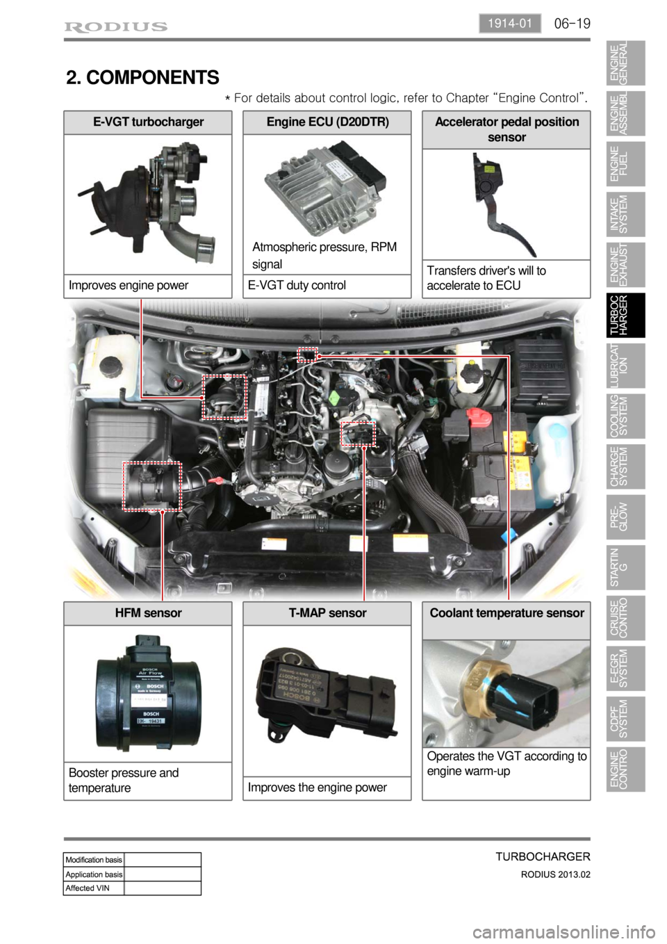
06-191914-01
2. COMPONENTS
Atmospheric pressure, RPM
signal * For details about control logic, refer to Chapter “Engine Control”.
E-VGT turbocharger
Improves engine powerAccelerator pedal position
sensor
Transfers driver's will to
accelerate to ECUEngine ECU (D20DTR)
E-VGT duty control
Coolant temperature sensor
Operates the VGT according to
engine warm-upT-MAP sensor
Improves the engine powerHFM sensor
Booster pressure and
temperature
Page 272 of 796
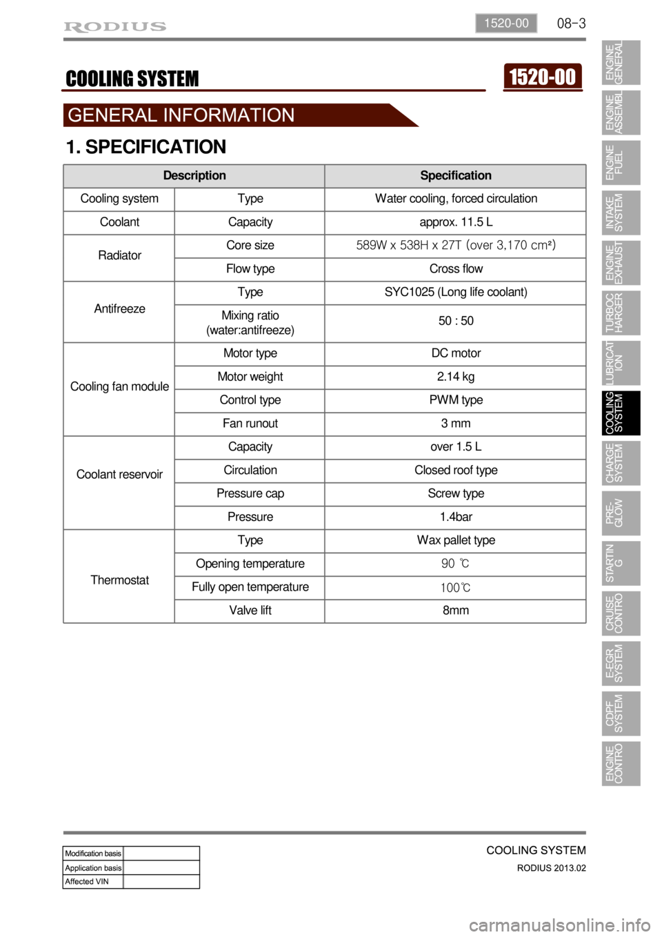
08-31520-00
1. SPECIFICATION
Description Specification
Cooling system Type Water cooling, forced circulation
Coolant Capacity approx. 11.5 L
RadiatorCore size589W x 538H x 27T (over 3,170 cm²)
Flow type Cross flow
AntifreezeType SYC1025 (Long life coolant)
Mixing ratio
(water:antifreeze)50 : 50
Cooling fan moduleMotor type DC motor
Motor weight 2.14 kg
Control type PWM type
Fan runout 3 mm
Coolant reservoirCapacity over 1.5 L
Circulation Closed roof type
Pressure cap Screw type
Pressure 1.4bar
ThermostatType Wax pallet type
Opening temperature90 ℃
Fully open temperature
100℃
Valve lift 8mm
Page 273 of 796

08-4
2. INSPECTION
Possible Cause Action
Coolant level
is
too low- Leak from the radiator
- Leak from the coolant auxiliary tank
- Leak from the heater core- Change the radiator
- Change the coolant auxiliary tank
- Change the heater
- Leak from the coolant hose
connections
- Damaged coolant hose - Reconnect the hose or replace
the clamp
- Change the hose
- Leak from the water pump gasket
- Leak from the water pump internal
seal- Change the gasket
- Change the water pump
- Leak from the water inlet cap
- Leak from the thermostat housing- Change the water inlet cap
gasket
- Change the thermostat sealing
- Incorrect tightening torque of the
cylinder head bolts
- Damaged cylinder head gasket- Tighten the bolts to the specified
torque
- Change the cylinder head gasket
Coolant
temperature is
too high- Coolant leakage (Coolant level is low)
- Improper coolant mixture ratio
- Kinked coolant hose- Add coolant
- Check the coolant concentration
(Anti-freeze)
- Repair or replace the hose
- Defective thermostat
- Defective water pump
- Defective radiator
- Defective coolant auxiliary tank or tank
cap- Change the thermostat
- Change the water pump
- Change the radiator
- Change the coolant auxiliary tank
or tank cap
- Cracks on the cylinder block or
cylinder head
- Clogged coolant passages in the
cylinder block or cylinder head- Change cylinder block or cylinder
head
- Clean the coolant passage
- Clogged radiator core - Clean the radiator core
- Improper operation of cooling fan - Replace the cooling fan or repair
the related circuit
- Defective temperature sensor or
faulty wiring- Replace the sensor or repair the
related wiring
Coolant
temperature is
too low- Thermostat is stuck open - Change the thermostat
- Improper operation of cooling fan - Replace the cooling fan or repair
the related circuit
- Defective temperature sensor or faulty
wiring- Replace the sensor or repair the
related wiring
Page 274 of 796
08-51520-00
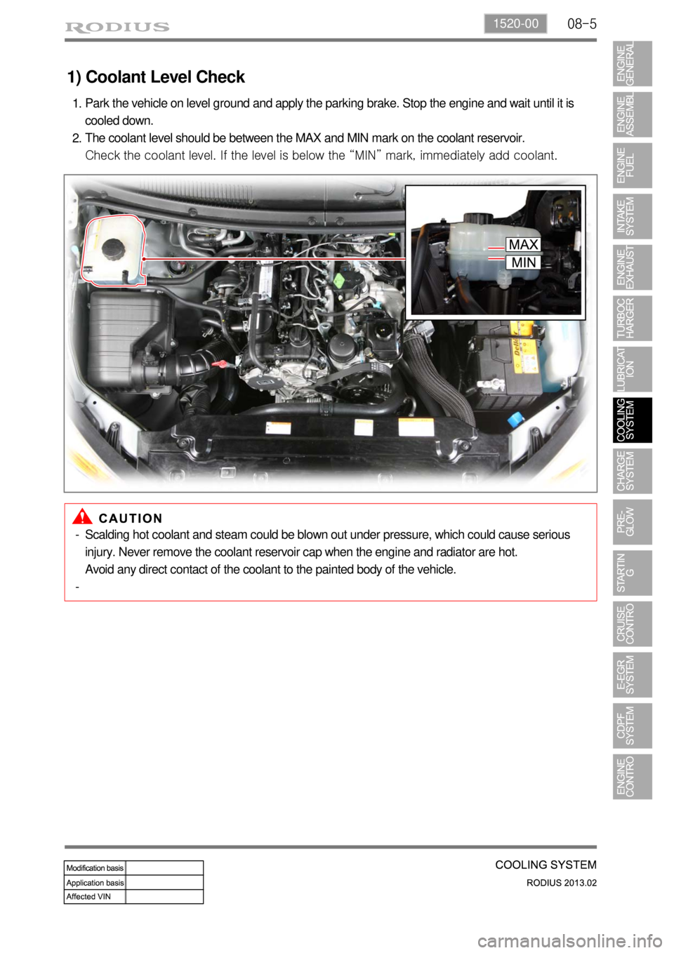
1) Coolant Level Check
Park the vehicle on level ground and apply the parking brake. Stop the engine and wait until it is
cooled down.
The coolant level should be between the MAX and MIN mark on the coolant reservoir.
Check the coolant level. If the level is below the “MIN” mark, immediately add coolant. 1.
2.
Scalding hot coolant and steam could be blown out under pressure, which could cause serious
injury. Never remove the coolant reservoir cap when the engine and radiator are hot.
Avoid any direct contact of the coolant to the painted body of the vehicle. -
-
Page 275 of 796
08-6
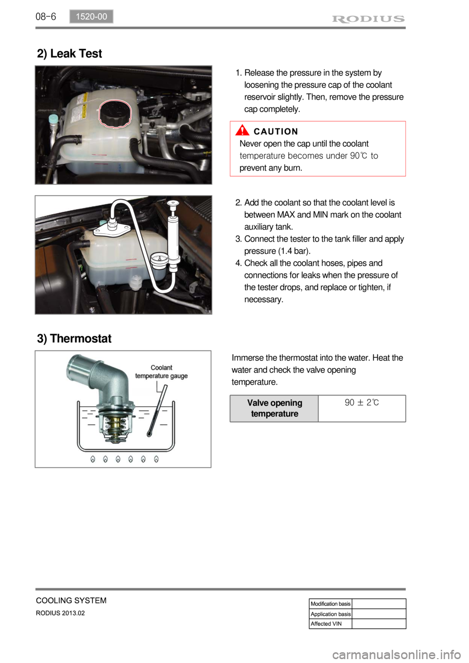
2) Leak Test
Release the pressure in the system by
loosening the pressure cap of the coolant
reservoir slightly. Then, remove the pressure
cap completely. 1.
Never open the cap until the coolant
temperature becomes under 90℃ to
prevent any burn.
Add the coolant so that the coolant level is
between MAX and MIN mark on the coolant
auxiliary tank.
Connect the tester to the tank filler and apply
pressure (1.4 bar).
Check all the coolant hoses, pipes and
connections for leaks when the pressure of
the tester drops, and replace or tighten, if
necessary. 2.
3.
4.
3) Thermostat
Immerse the thermostat into the water. Heat the
water and check the valve opening
temperature.
Valve opening
temperature 90 ± 2℃
Page 276 of 796
08-71520-00
3. CAUTIONS
If 100% of anti-freeze is added, the water pump vane can be damaged and thermal conductivity
can be decreased resulting in poor circulation in the cooling system which leads to overheated
engine.
Use of non-recommended coolant could cause damage to the cooling system and overheating of
the engine.
Opening the coolant reservoir cap while the engine is running or hot can cause burns by hot
steam or water.
To open the coolant reservoir cap, wrap the cap with a wet towel or thick cloth after the engine is
cooled down sufficiently.
If cool water is added to the heated engine, the engine or radiator can be deformed.
The anti-freeze in the coolant can damage the painted surface, so avoid the contact of the coolant
to the painted body.
The anti-freeze and water should be mixed in proper mixture ratio. Never add only water when
adding coolant.
If the anti-freeze content is too low, the coolant can be frozen while the engine can be overheated
if anti-freeze content is too high. -
-
-
-
-
-
-
-
Page 277 of 796
08-8
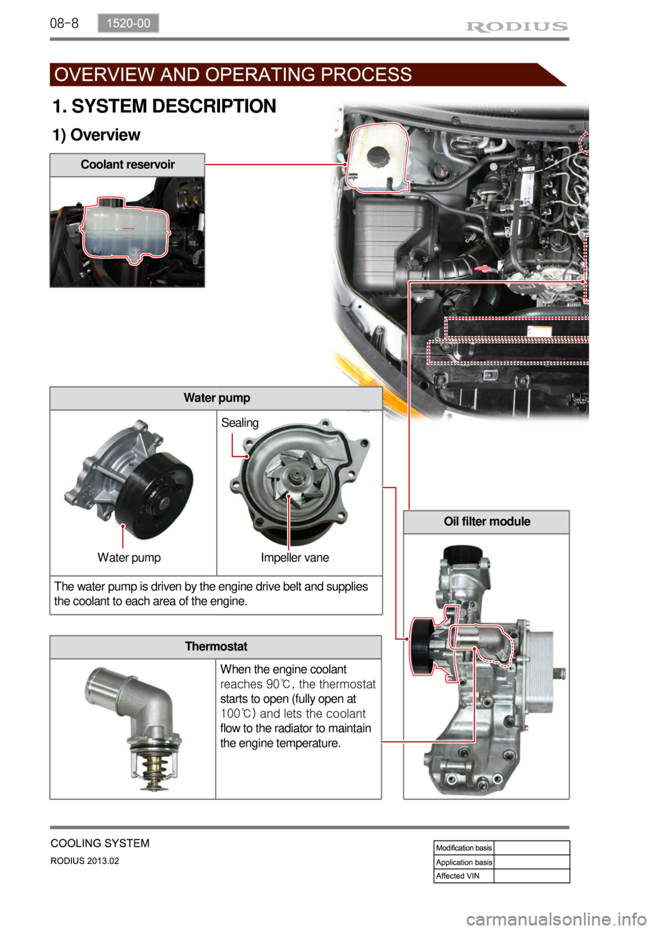
Coolant reservoir
Oil filter module
Thermostat
When the engine coolant
reaches 90℃, the thermostat
starts to open (fully open at
100℃) and lets the coolant
flow to the radiator to maintain
the engine temperature.
Water pump
The water pump is driven by the engine drive belt and supplies
the coolant to each area of the engine.
1. SYSTEM DESCRIPTION
1) Overview
Water pump Impeller vaneSealing