service SSANGYONG TURISMO 2013 User Guide
[x] Cancel search | Manufacturer: SSANGYONG, Model Year: 2013, Model line: TURISMO, Model: SSANGYONG TURISMO 2013Pages: 796, PDF Size: 78.99 MB
Page 234 of 796

04-31719-00
1. SPECIFICATIONS
Shorten the service interval under severe conditions such as driving on a dusty road or off-road. *
Unit Description Specification
Air cleaner elementFilter type Dry, filter element
Initial resistance Max. 300 mmAq
Service interval EU: Change every 20,000 km
GEN: Change every 15,000 km
Air cleaner assemblyWeight 2.36kg
Operating temperature-30 ~ 100℃
IntercoolerRadiation over 13,000 Kcal
Pressure loss at turbocharger below 90 mmHg
Cooling type Air cooled type
Core size 450W*130H*70T
Core type C/FIN
Page 268 of 796
07-31543-00
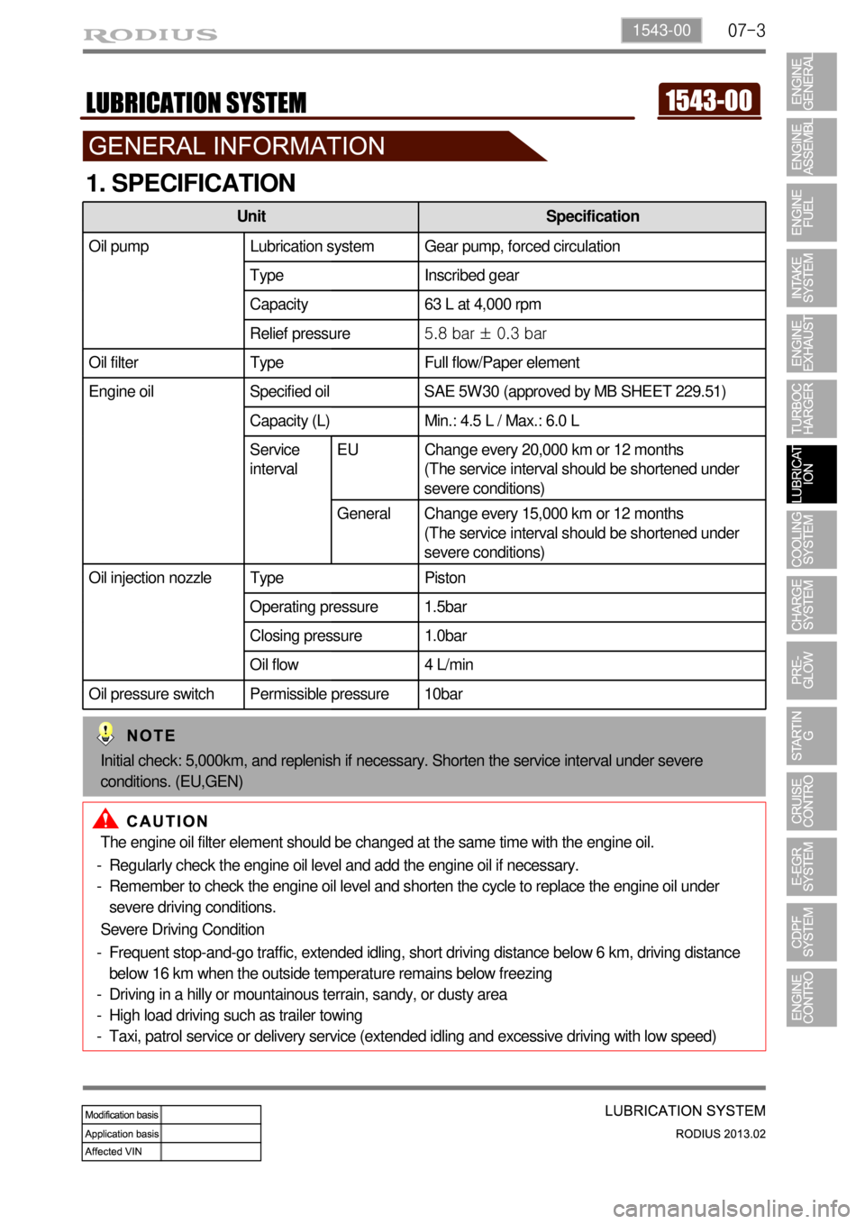
1. SPECIFICATION
The engine oil filter element should be changed at the same time with the engine oil.
Regularly check the engine oil level and add the engine oil if necessary.
Remember to check the engine oil level and shorten the cycle to replace the engine oil under
severe driving conditions. -
-
Severe Driving Condition
Frequent stop-and-go traffic, extended idling, short driving distance below 6 km, driving distance
below 16 km when the outside temperature remains below freezing
Driving in a hilly or mountainous terrain, sandy, or dusty area
High load driving such as trailer towing
Taxi, patrol service or delivery service (extended idling and excessive driving with low speed) -
-
-
-
Unit Specification
Oil pump Lubrication system Gear pump, forced circulation
Type Inscribed gear
Capacity 63 L at 4,000 rpm
Relief pressure5.8 bar ± 0.3 bar
Oil filter Type Full flow/Paper element
Engine oil Specified oil SAE 5W30 (approved by MB SHEET 229.51)
Capacity (L) Min.: 4.5 L / Max.: 6.0 L
Service
intervalEU Change every 20,000 km or 12 months
(The service interval should be shortened under
severe conditions)
General Change every 15,000 km or 12 months
(The service interval should be shortened under
severe conditions)
Oil injection nozzle Type Piston
Operating pressure 1.5bar
Closing pressure 1.0bar
Oil flow 4 L/min
Oil pressure switch Permissible pressure 10bar
Initial check: 5,000km, and replenish if necessary. Shorten the service interval under severe
conditions. (EU,GEN)
Page 315 of 796
14-32412-02
1. CAUTIONS
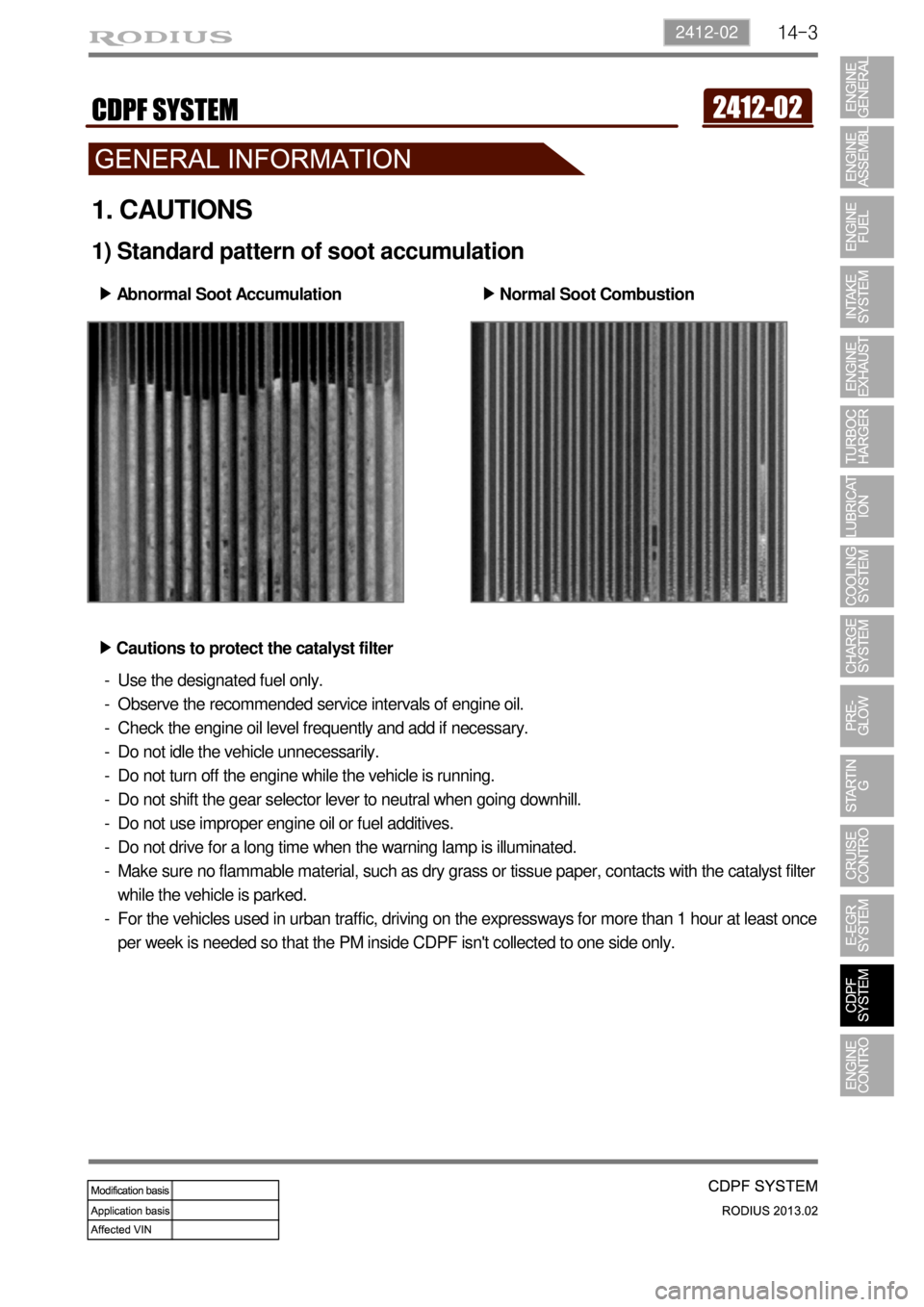
1) Standard pattern of soot accumulation
Abnormal Soot Accumulation ▶
Normal Soot Combustion ▶
Cautions to protect the catalyst filter ▶
Use the designated fuel only.
Observe the recommended service intervals of engine oil.
Check the engine oil level frequently and add if necessary.
Do not idle the vehicle unnecessarily.
Do not turn off the engine while the vehicle is running.
Do not shift the gear selector lever to neutral when going downhill.
Do not use improper engine oil or fuel additives.
Do not drive for a long time when the warning lamp is illuminated.
Make sure no flammable material, such as dry grass or tissue paper, contacts with the catalyst filter
while the vehicle is parked.
For the vehicles used in urban traffic, driving on the expressways for more than 1 hour at least once
per week is needed so that the PM inside CDPF isn't collected to one side only. -
-
-
-
-
-
-
-
-
-
Page 377 of 796
15-490000-00
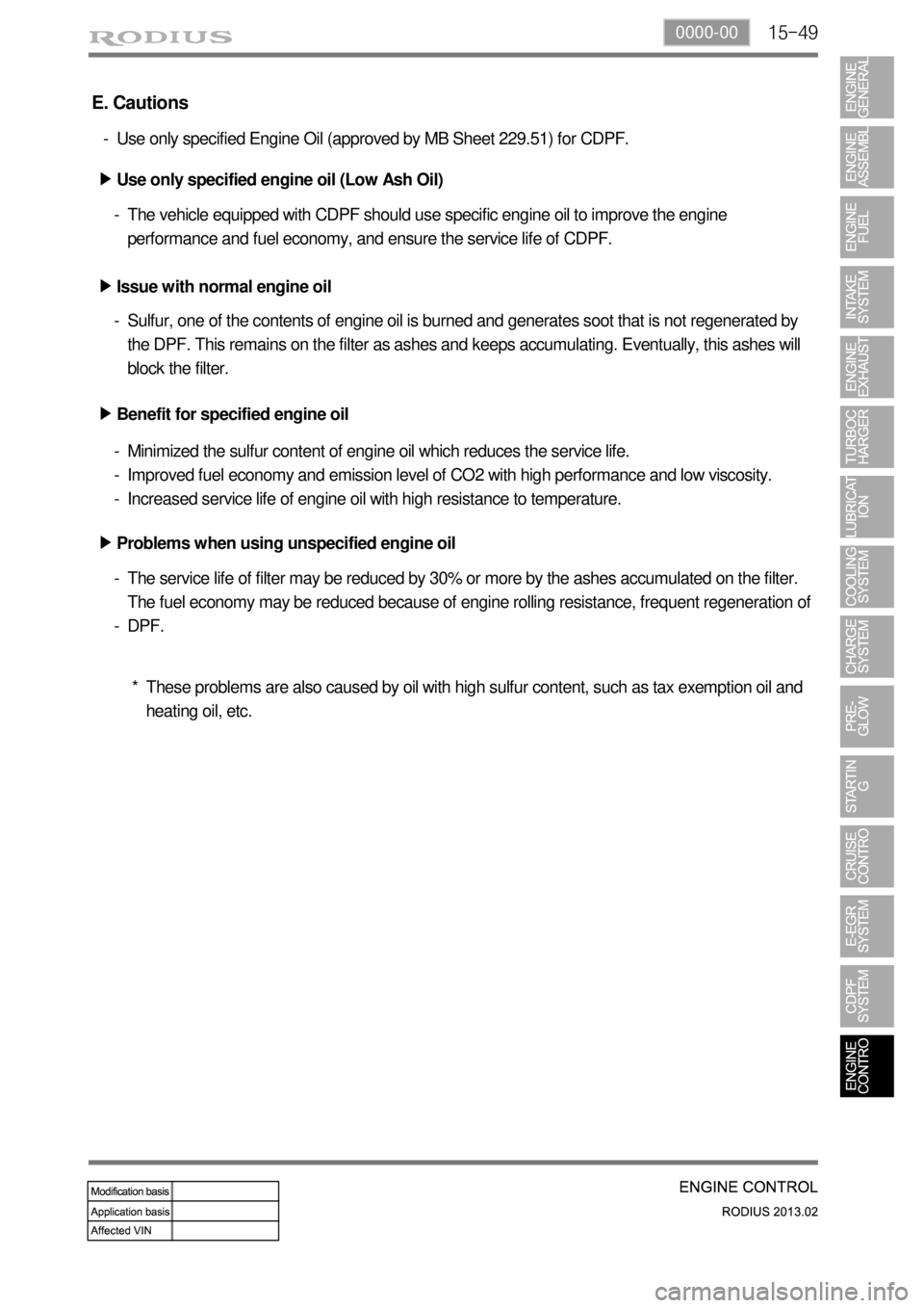
E. Cautions
Use only specified Engine Oil (approved by MB Sheet 229.51) for CDPF. -
Use only specified engine oil (Low Ash Oil) ▶
The vehicle equipped with CDPF should use specific engine oil to improve the engine
performance and fuel economy, and ensure the service life of CDPF. -
Issue with normal engine oil ▶
Sulfur, one of the contents of engine oil is burned and generates soot that is not regenerated by
the DPF. This remains on the filter as ashes and keeps accumulating. Eventually, this ashes will
block the filter. -
Benefit for specified engine oil ▶
Minimized the sulfur content of engine oil which reduces the service life.
Improved fuel economy and emission level of CO2 with high performance and low viscosity.
Increased service life of engine oil with high resistance to temperature. -
-
-
Problems when using unspecified engine oil ▶
The service life of filter may be reduced by 30% or more by the ashes accumulated on the filter.
The fuel economy may be reduced because of engine rolling resistance, frequent regeneration of
DPF. -
-
These problems are also caused by oil with high sulfur content, such as tax exemption oil and
heating oil, etc. *
Page 382 of 796

01-70000-00
2. DESCRIPTION AND OPERATION
1) Cleanliness and Care
An automobile engine is a combination of many machined, honed, polished and lapped surfaces with
tolerances that are measured in the ten-thousandths of an inch. When any internal engine parts are
serviced, care and cleanliness are important. A liberal coating of engine oil should be applied to friction
areas during assembly, to protect and lubricate the surfaces on initial operation.
Proper cleaning and protection of machined surfaces and friction areas is part of the repair procedure.
This is considered standard shop practice even if not specifically stated.
Whenever valve train components are removed for service, they should be kept in order.
They should be installed in the same locations, and with the same mating surfaces, as when they were
removed. Battery cables should be disconnected before any major work is performed on the engine.
Failure to disconnect cables may result in damage to wire harness or other electrical parts.
2) On-Engine Service
Disconnect the negative battery cable before removing or installing any electrical unit, or when a
tool or equipment could easily come in contact with exposed electrical terminals.
Disconnecting this cable will help prevent personal injury and damage to the vehicle.
The ignition must also be in LOCK unless otherwise noted.
Notice Any time the air cleaner is removed, the intake opening -
Any time the air cleaner is removed, the intake opening should be covered. This will protect
against accidental entrance of foreign material, which could follow the intake passage into the
cylinder and cause extensive damage when the engine is started. -
Page 403 of 796
08-51452-01
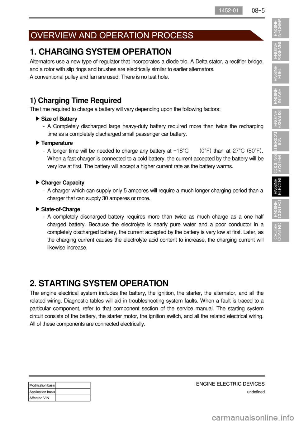
1. CHARGING SYSTEM OPERATION
Alternators use a new type of regulator that incorporates a diode trio. A Delta stator, a rectifier bridge,
and a rotor with slip rings and brushes are electrically similar to earlier alternators.
A conventional pulley and fan are used. There is no test hole.
1) Charging Time Required
The time required to charge a battery will vary depending upon the following factors:
Size of Battery ▶
A Completely discharged large heavy-duty battery required more than twice the recharging
time as a completely discharged small passenger car battery. -
Temperature ▶
A longer time will be needed to charge any battery at -18°C (0°F) than at 27°C (80°F).
When a fast charger is connected to a cold battery, the current accepted by the battery will be
very low at first. The battery will accept a higher current rate as the battery warms. -
Charger Capacity ▶
A charger which can supply only 5 amperes will require a much longer charging period than a
charger that can supply 30 amperes or more. -
State-of-Charge ▶
A completely discharged battery requires more than twice as much charge as a one half
charged battery. Because the electrolyte is nearly pure water and a poor conductor in a
completely discharged battery, the current accepted by the battery is very low at first. Later, as
the charging current causes the electrolyte acid content to increase, the charging current will
likewise increase. -
2. STARTING SYSTEM OPERATION
The engine electrical system includes the battery, the ignition, the starter, the alternator, and all the
related wiring. Diagnostic tables will aid in troubleshooting system faults. When a fault is traced to a
particular component, refer to that component section of the service manual. The starting system
circuit consists of the battery, the starter motor, the ignition switch, and all the related electrical wiring.
All of these components are connected electrically.
Page 404 of 796

08-6
3. IGNITION SYSTEM OPERATION
This ignition system does not use a conventional distributor and coil. It uses a crankshaft position
sensor input to the Engine Control Module (ECM).
The ECM then determines Electronic Spark Timing (EST) and triggers the electronic ignition system
ignition coil.
This type of distributor less ignition system uses a "waste spark" method of spark distribution. Each
cylinder is paired with the cylinder that is opposite it (2.3L DOHC: 2 - 3 or 1 - 4, 3.2L DOHC: 1 - 6 or 2 -
5 or 3 - 4).
The spark occurs simultaneously in the cylinder coming up on the compression stroke and in the
cylinder coming up on the exhaust stroke.
The cylinder on the exhaust stroke requires very little of the available energy to fire the spark plug.
The remaining energy is available to the spark plug in the cylinder on the compression stroke. These
systems use the EST signal from the ECM to control the EST.
The ECM uses the following information: Engine load (mass air flow sensor, manifold air pressure
sensor).
Engine coolant temperature.
Intake air temperature.
Crankshaft position.
Engine speed (rpm).
1) Electronic Ignition System Ignition Coil
The Electronic Ignition (EI) system ignition coil is located on the cylinder head cover.
The double ended coils receive the signal for the ECM which controls the spark advance. Each
EI system ignition coil provides the high voltage to two spark plugs simultaneously;
3.2L DOHC
T1/1: cylinder 2 and 5
T1/2: cylinder 3 and 4
T1/3: cylinder 1 and 6
The EI system ignition coil is not serviceable and must be replaced as an assembly.
Page 477 of 796

03-37010-06
1. SPECIFICATIONS
Item Item Specification
Immobilizer
unitOperating voltage
(CAN) 6.0 V to 16.0 V
(6.0 V ~18.0 V)
Operating temperature-30℃ ~ 80℃
Coil inductance420 uH ± 20 uH
Modulation methodFSK
(Frequency Shift Keying : frequency
displacement)
Frequency134.2 KHz ± 4 KHz
TransponderFrequency134.2 KHz ± 4 KHz
Operating temperature-40℃ ~ +85℃
Transponder coding Up to 5
2. CAUTIONS
The vehicle owner must observe the service works when deleting the transponder codes or
registering additional keys.
In any cases, the immobilizer system can not be removed from the vehicle. If you attempt to
remove it and damage the system, starting will be impossible, so never attempt to remove,
damage or modify it.
The remote engine starter cannot be installed to the vehicle equipped with the immobilizer
system.
Do not drop or shock to the transponder in the ignition key as it may be damaged.
With a damaged transponder, the engine cannot be started.
For the vehicle with the immobilizer, there can be a problem in starting the vehicle or the system
error: 1.
2.
3.
4.
5.
6.
When more than one immobilizer keys come into contact with (each) other(s) or key is close
to any device sending or receiving electromagnetic fields or waves
When the ignition key is close to any electronic or electric devices such as lighting equipment,
security keys or security cards
When the ignition key is close to a magnetic or metal object or a battery -
-
-
Page 544 of 796

11-78910-05
3. CAUTIONS AND WARNING FOR SAFETY
Ssangyong is not liable for any personal injury and material damage, caused by violation of traffic
regulations or neglect of observing actual traffic and driving situations.
Colors on display figures in this manual may differ from actual display due to publication concerns. -
-
Do not disassemble or modify this system.
If doing so, it may cause an accident, fire or electric shock.
Do not use the system if it is malfunctioning (sound or video output problem).
Doing so may lead to an accident or electric shock.
Please contact a Ssangyong service dealer immediately.
The system should be used only when the engine is started.
Using the system for an extended period of the with the engine off may discharge the battery.
Do not leave beverages or foreign materials around the system.
If they enter the system, they may cause a fire.
The system may break down if a disc not supported by this system is inserted.
Do not apply impact to or drop this system.
It might cause malfunction.
Never leave the system in a hot or cold place for an extended period of time. Therefore, do not park
the vehicle in a hot or cold place. The ambient temperature should be -30℃ ~ +80℃ for
proper operation. -
-
-
-
-
-
-
Page 556 of 796
01-53650-01
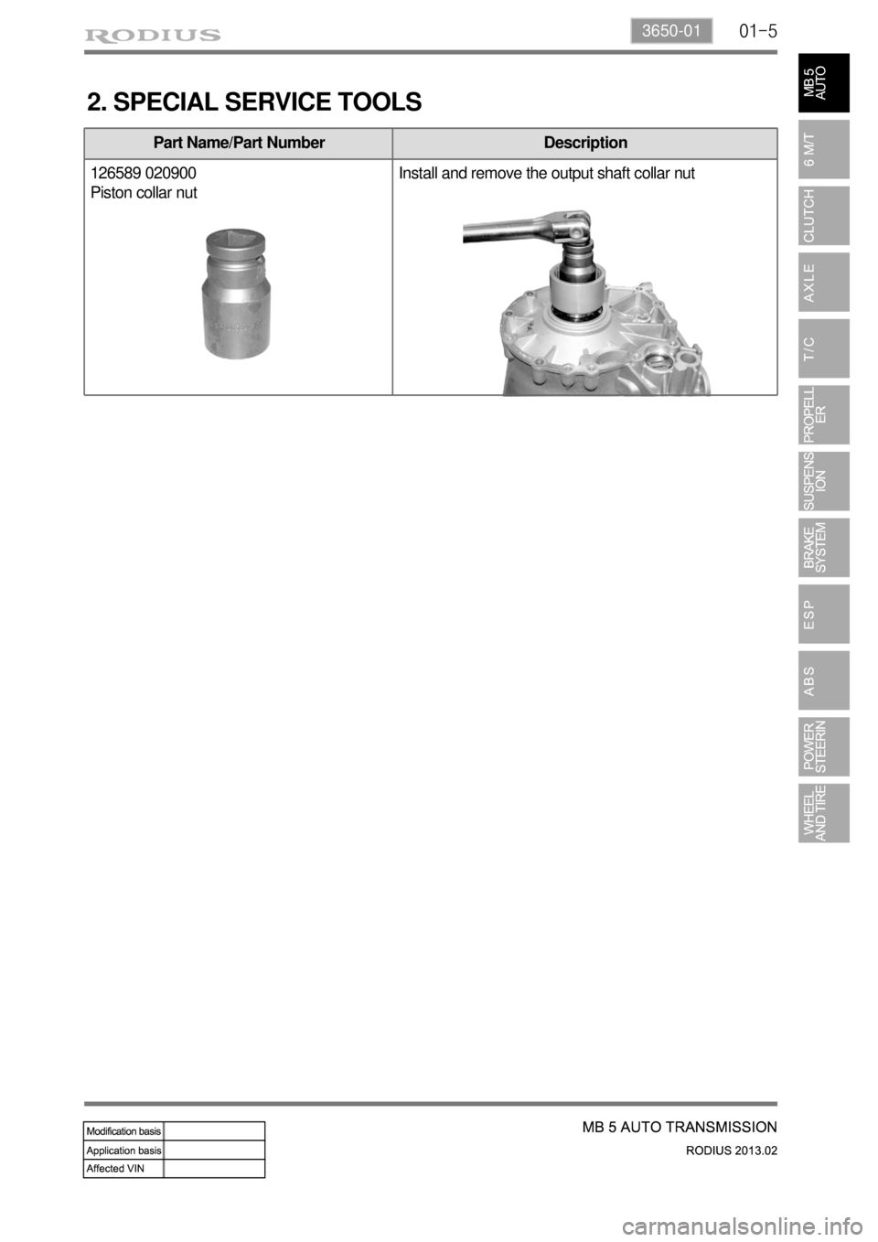
Part Name/Part Number Description
126589 020900
Piston collar nutInstall and remove the output shaft collar nut
2. SPECIAL SERVICE TOOLS