level SSANGYONG TURISMO 2013 Owner's Manual
[x] Cancel search | Manufacturer: SSANGYONG, Model Year: 2013, Model line: TURISMO, Model: SSANGYONG TURISMO 2013Pages: 796, PDF Size: 78.99 MB
Page 340 of 796

15-12
(2) Fuel injection control
a. Multi injection
Fuel injection process consists of 3 steps: Main Injection, Pilot Injection, Post Injection
This is the injection before main injection. This consists of 1st and 2nd pilot injection, and Pre-injection.
The steps are normally used to control the NOx, noise, idle stability and engine vibration. Inject a small
amount of fuel before main injection prevents the instant high combustion temperature. It reduces the
NOx and decreases the engine noise and vibration. The main injection produces the actual output.
The vehicle output is based on the main injection. The post injection is the injection process after main
injection and consists of ‘After injection”, “Post 1 injection” and “Post 2 injection”. All of post
injections are to reduce the PM and harmful exhaust gas. The post injection does not make the actual
output. The post injection activates the fuel by injecting the fuel to the incompletely combusted gas
after primary combustion. Through the process, the PM and smoke in the exhaust gas could be
reduced. There are totally 7 injections as shown in the figure. However, all of 7 injections are not
performed during driving because it decreases the fuel economy. Totally 5 injections can be performed
in one cycle.
InjectionFunction
MainProduces engine power
Pilot 1Reduces PM by injecting before
main injection.AfterPM control
Pilot 2Reduces NOx and noise by
shortening main injection delay
due to flammability Post 1Reduces PM by enabling fuel
activation.
PreControls NOx emission level,
Combustion noise and
Stable idle Post 2
Activates CDPF by increasing
exhaust gas temperature and
supplying reduction material
Page 350 of 796
15-22
(7) Knocking Control
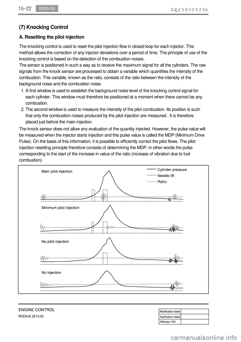
A. Resetting the pilot injection
The knocking control is used to reset the pilot injection flow in closed loop for each injector. This
method allows the correction of any injector deviations over a period of time. The principle of use of the
knocking control is based on the detection of the combustion noises.
The sensor is positioned in such a way as to receive the maximum signal for all the cylinders. The raw
signals from the knock sensor are processed to obtain a variable which quantifies the intensity of the
combustion. This variable, known as the ratio, consists of the ratio between the intensity of the
background noise and the combustion noise.
A first window is used to establish the background noise level of the knocking control signal for
each cylinder. This window must therefore be positioned at a moment when there cannot be any
combustion.
The second window is used to measure the intensity of the pilot combustion. Its position is such
that only the combustion noises produced by the pilot injection are measured . It is therefore
placed just before the main injection. 1.
2.
The knock sensor does not allow any evaluation of the quantity injected. However, the pulse value will
be measured when the injector starts injection and this pulse value is called the MDP (Minimum Drive
Pulse). On the basis of this information, it is possible to efficiently correct the pilot flows. The pilot
injection resetting principle therefore consists of determining the MDP, in other words the pulse
corresponding to the start of the increase in value of the ratio (increase of vibration due to fuel
combustion).
Page 356 of 796

15-28
Electric throttle
bodyAccelerator
pedal
moduleD20DTR
ECU
(9) EGR control
A. Overview
The EGR (Electric-Exhaust Gas Recirculation) valve reduces the NOx emission level by recirculating
some of the exhaust gas to the intake system.
To meet Euro-V regulation, the capacity and response rate of E-EGR valve in D20DTR engine have
been greatly improved. The EGR cooler with high capacity reduces the Nox, and the bypass valve
reduces the CO and HC due to EGR gas before warming up.
Also, the engine ECU adjusts the E-EGR opening by using the air mass signal through HFM sensor. If
the exhaust gas gets into the intake manifold when the EGR valve is open, the amount of fresh air
through HFM sensor should be decresed.
B. Components
E-EGR cooler
Coolant
temperature
sensorOxygen sensor
HFM (intake
air
temperature)
Crankshaft
position
sensorE-EGR valve
T-MAP
sensor
Page 358 of 796

15-30
D. Bypass control for EGR cooler
Cooler temperature ▶
When the coolant temperature is below 70℃, the exhaust gas is bypassed the EGR cooler.
Exhaust gas temperature ▶
When the exhaust gas tem
perature is below 300℃, the exhaust gas is bypassed the EGR cooler
Otherwise, PM could be increased due to too low exhaust gas temperature.
E. Control elements for EGR system
Accelerator pedal (engine load) - Indicates the driver's intention and engine load. If the load goes
up, the EGR ratio is decreased.
T-MAP (boost pressure map stored in ECU) - Compensates the difference in boost pressure by
adjusting EGR ratio.
Engine rpm - Used as the signal for determining EGR operating range.
Coolant temperature - When the coolant temperature is low, NOx is decreased but PM could be
increased. So, to reduce PM, decrease EGR ratio when the coolant temperature is low.
Intake air mass and temperature - HFM sensor measures the intake air mass to calculate the
actual EGR volume. If the air mass is larger than programmed value in map, EGR ratio will be
higher.
EGR position sensor - Detects the actual opening angle of EGR valve and performs feedback
function according to PWM control by ECU.
Wide band oxygen sensor - Detects the oxygen volume in exhaust gas to check if the EGR ratio is
proper.
Electronic throttle body - Keeps EGR ratio to optimized level by controlling the throttle body in EGR
operating range (decreasing pressure in intake manifold). -
-
-
-
-
-
-
-
Page 366 of 796
15-38
Relay box
A/C
compressorHFM (intake air
temperature)Cooling fan
module
MB 5 A/T (ATF
temperature)Coolant
temperature
sensor
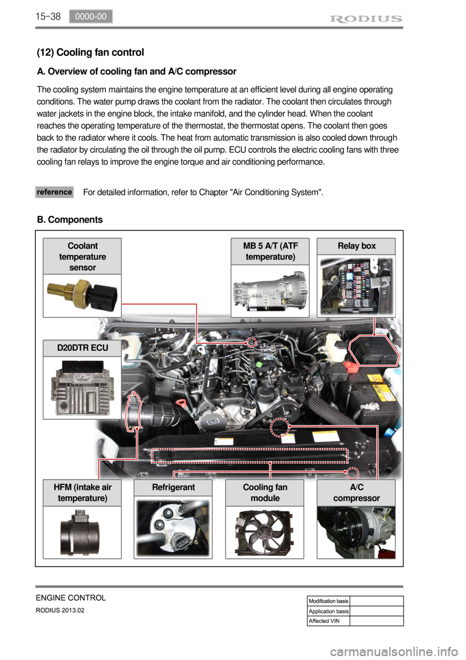
(12) Cooling fan control
A. Overview of cooling fan and A/C compressor
The cooling system maintains the engine temperature at an efficient level during all engine operating
conditions. The water pump draws the coolant from the radiator. The coolant then circulates through
water jackets in the engine block, the intake manifold, and the cylinder head. When the coolant
reaches the operating temperature of the thermostat, the thermostat opens. The coolant then goes
back to the radiator where it cools. The heat from automatic transmission is also cooled down through
the radiator by circulating the oil through the oil pump. ECU controls the electric cooling fans with three
cooling fan relays to improve the engine torque and air conditioning performance.
For detailed information, refer to Chapter "Air Conditioning System".
B. Components
D20DTR ECU
Refrigerant
Page 377 of 796
15-490000-00
E. Cautions
Use only specified Engine Oil (approved by MB Sheet 229.51) for CDPF. -
Use only specified engine oil (Low Ash Oil) ▶
The vehicle equipped with CDPF should use specific engine oil to improve the engine
performance and fuel economy, and ensure the service life of CDPF. -
Issue with normal engine oil ▶
Sulfur, one of the contents of engine oil is burned and generates soot that is not regenerated by
the DPF. This remains on the filter as ashes and keeps accumulating. Eventually, this ashes will
block the filter. -
Benefit for specified engine oil ▶
Minimized the sulfur content of engine oil which reduces the service life.
Improved fuel economy and emission level of CO2 with high performance and low viscosity.
Increased service life of engine oil with high resistance to temperature. -
-
-
Problems when using unspecified engine oil ▶
The service life of filter may be reduced by 30% or more by the ashes accumulated on the filter.
The fuel economy may be reduced because of engine rolling resistance, frequent regeneration of
DPF. -
-
These problems are also caused by oil with high sulfur content, such as tax exemption oil and
heating oil, etc. *
Page 391 of 796
05-32420-01
1. OVERVIEW OF EXHAUST SYSTEM
When you are inspecting or replacing exhaust system components, make sure there is adequate
clearance from all points on the underbody to avoid possible overheating of the floor panel and
possible damage to the passenger compartment insulation and trim materials.
Check the complete exhaust system and the nearby body areas and trunk lid for broken,
damaged, missing or mispositioned parts, open seams, holes, loose connections, or othe
r
deterioration which could permit exhaust fumes to seep into the trunk may be an indication of a
problem in one of these areas. Any defects should be corrected immediately. -
2. OVERVIEW OF MUFFLER
Aside from the exhaust manifold connection, the exhaust system uses a flange and seal joint design
rather than a slip joint coupling design with clamp and U-bolts.
If hole, open seams, or any deterioration is discovered upon inspection of the front muffler and pipe
assembly, the complete assembly should be replace, the complete assembly should be replaced.
The same procedure is applicable to the rear muffler assembly. Heat shields for the front and rea
r
muffler assembly and catalytic converter protect the vehicle and the environment from the high
temperatures that the exhaust system develops.
3. OVERVIEW OF CATALYTIC CONVERTER
When jacking or lifting the vehicle from the body side rails, be certain that the lift pads do not
contact the catalytic converter, as this could damage the catalytic converter. -
Use of anything other than unleaded fuel will damage the catalyst in the catalytic converter. -
The catalytic converter are emission-control devices added to the exhaust system to reduce
pollutants from the exhaust pipes.
The oxidation catalyst is coated with a catalytic material containing platinum and palladium,
which reduces levels of hydrocarbon (HC) and carbon monoxide (CO) from the exhaust gas.
The three-way catalyst has coatings which contain platinum and rhodium, which additionall
y
lower the levels of oxides of nitrogen (NOx). -
-
Page 398 of 796
07-6
1. GENERAL DESCRIPTION
The cooling system maintains the engine temperature at an efficient level during all engine operating
conditions. When the engine is cold, the cooling system cools the engine slowly or not at all. This slo
w
cooling of the engine allows the engine to warm up quickly. The cooling system includes a radiator and
recovery subsystem, cooling fans, a thermostat and housing, a water pump, and a water pump drive
belt. The timing belt drives the water pump. All components must function properly for the cooling
system to operation. The water pump draws the coolant from the radiator.
The coolant then circulates through water jackets in the engine block, the intake manifold, and the
cylinder head. When the coolant reaches the operating temperature of the thermostat, the thermostat
opens. The coolant then goes back to the radiator where it cools. This system directs some coolant
through the hoses to the heat core. This provides for heating and defrosting. The coolant reservoir is
connected to the radiator to recover the coolant displaced by expansion from the high temperatures.
The coolant reservoir maintains the correct coolant level. The cooling system for this vehicle has no
radiator cap or filler neck. The coolant is added to the cooling system through the coolant reservoir.
Page 498 of 796

07-12
(2) Head lamp leveling device
Page 508 of 796
06-8
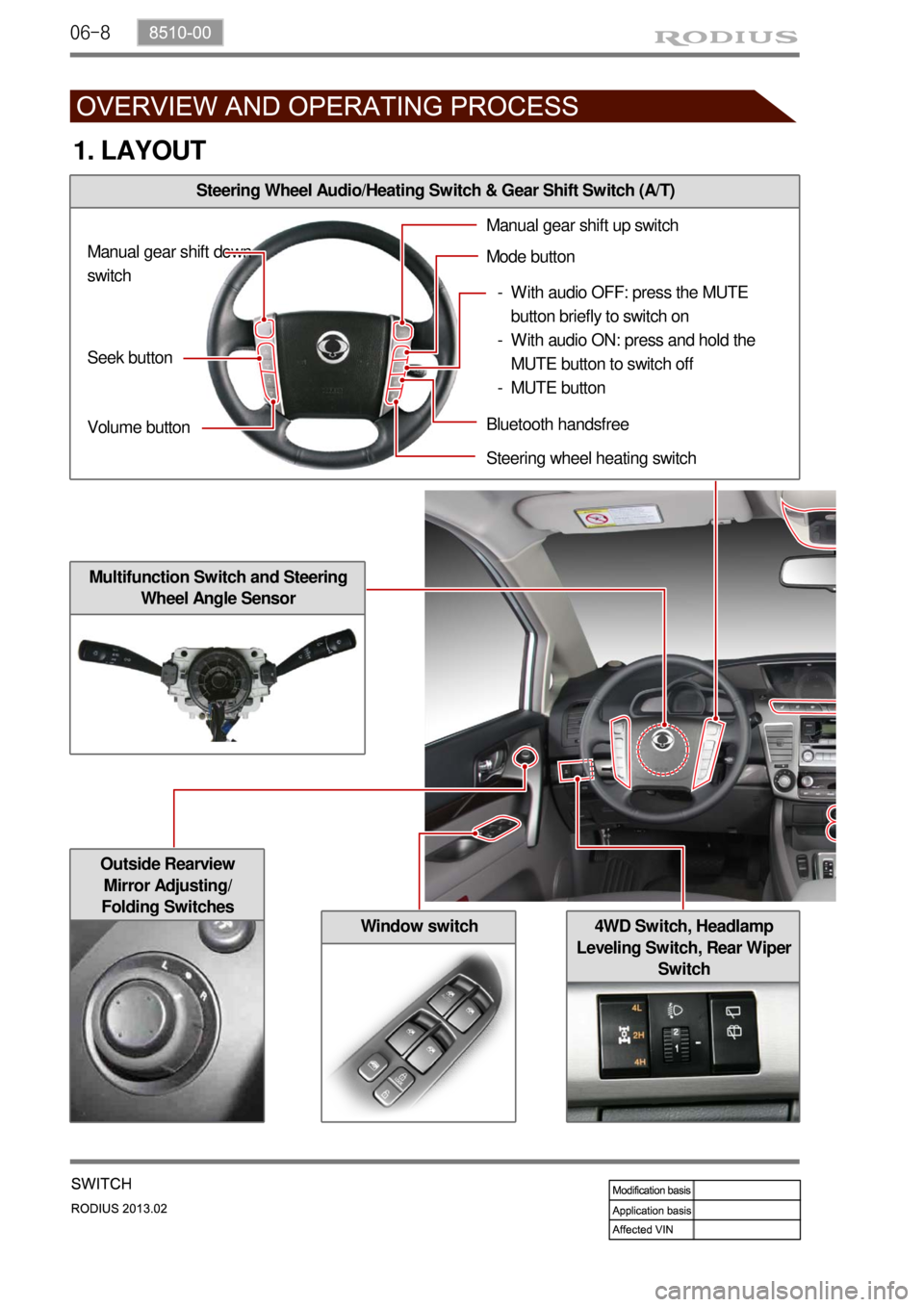
Outside Rearview
Mirror Adjusting/
Folding Switches
Window switch
Steering Wheel Audio/Heating Switch & Gear Shift Switch (A/T)
Multifunction Switch and Steering
Wheel Angle Sensor
4WD Switch, Headlamp
Leveling Switch, Rear Wiper
Switch
1. LAYOUT
Seek button
Volume button Manual gear shift down
switchManual gear shift up switch
Mode button
Bluetooth handsfree
Steering wheel heating switch
With audio OFF: press the MUTE
button briefly to switch on
With audio ON: press and hold the
MUTE button to switch off
MUTE button -
-
-