level SSANGYONG TURISMO 2013 User Guide
[x] Cancel search | Manufacturer: SSANGYONG, Model Year: 2013, Model line: TURISMO, Model: SSANGYONG TURISMO 2013Pages: 796, PDF Size: 78.99 MB
Page 268 of 796
07-31543-00
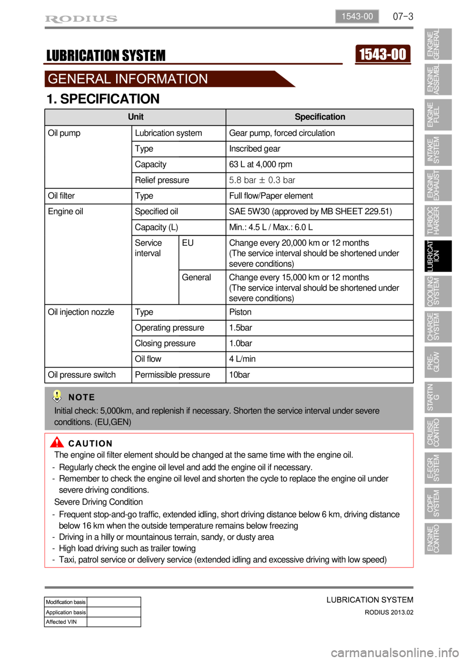
1. SPECIFICATION
The engine oil filter element should be changed at the same time with the engine oil.
Regularly check the engine oil level and add the engine oil if necessary.
Remember to check the engine oil level and shorten the cycle to replace the engine oil under
severe driving conditions. -
-
Severe Driving Condition
Frequent stop-and-go traffic, extended idling, short driving distance below 6 km, driving distance
below 16 km when the outside temperature remains below freezing
Driving in a hilly or mountainous terrain, sandy, or dusty area
High load driving such as trailer towing
Taxi, patrol service or delivery service (extended idling and excessive driving with low speed) -
-
-
-
Unit Specification
Oil pump Lubrication system Gear pump, forced circulation
Type Inscribed gear
Capacity 63 L at 4,000 rpm
Relief pressure5.8 bar ± 0.3 bar
Oil filter Type Full flow/Paper element
Engine oil Specified oil SAE 5W30 (approved by MB SHEET 229.51)
Capacity (L) Min.: 4.5 L / Max.: 6.0 L
Service
intervalEU Change every 20,000 km or 12 months
(The service interval should be shortened under
severe conditions)
General Change every 15,000 km or 12 months
(The service interval should be shortened under
severe conditions)
Oil injection nozzle Type Piston
Operating pressure 1.5bar
Closing pressure 1.0bar
Oil flow 4 L/min
Oil pressure switch Permissible pressure 10bar
Initial check: 5,000km, and replenish if necessary. Shorten the service interval under severe
conditions. (EU,GEN)
Page 269 of 796
07-4
2. MAINTENANCE
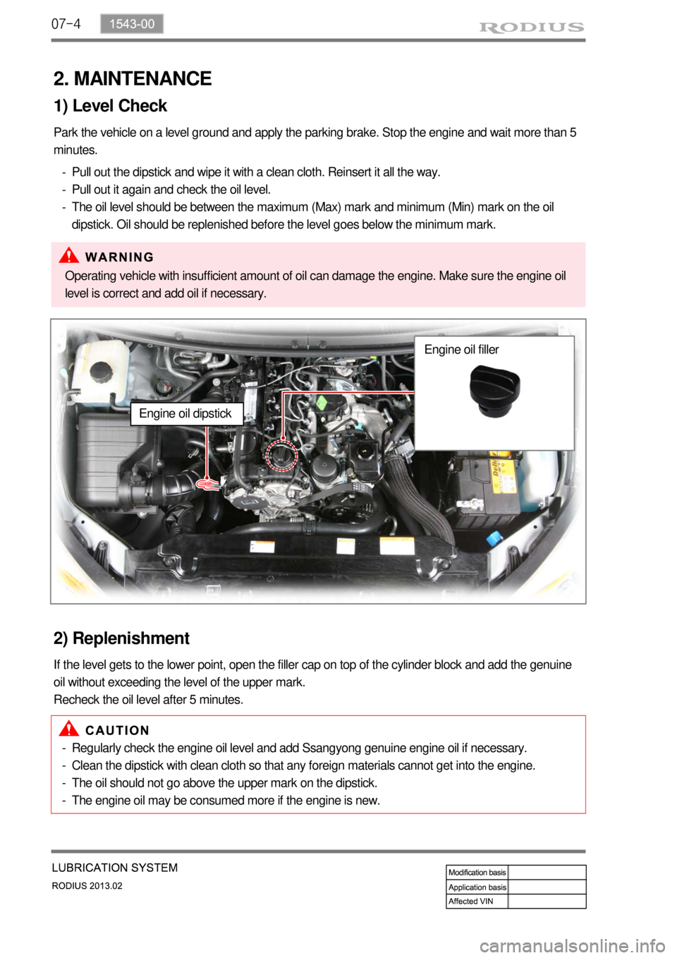
1) Level Check
Park the vehicle on a level ground and apply the parking brake. Stop the engine and wait more than 5
minutes.
Pull out the dipstick and wipe it with a clean cloth. Reinsert it all the way.
Pull out it again and check the oil level.
The oil level should be between the maximum (Max) mark and minimum (Min) mark on the oil
dipstick. Oil should be replenished before the level goes below the minimum mark. -
-
-
Operating vehicle with insufficient amount of oil can damage the engine. Make sure the engine oil
level is correct and add oil if necessary.
2) Replenishment
If the level gets to the lower point, open the filler cap on top of the cylinder block and add the genuine
oil without exceeding the level of the upper mark.
Recheck the oil level after 5 minutes.
Regularly check the engine oil level and add Ssangyong genuine engine oil if necessary.
Clean the dipstick with clean cloth so that any foreign materials cannot get into the engine.
The oil should not go above the upper mark on the dipstick.
The engine oil may be consumed more if the engine is new. -
-
-
-
Engine oil dipstick
Engine oil filler
Page 270 of 796
07-51543-00
1. SYSTEM DESCRIPTION
1) Overview
The lubrication system supplies oil to each lubrication section to prevent friction and wear and to
remove heat from the friction part. As the engine runs, frictional heat is generated on each lubrication
section. If this condition persists, the bearing can be burned and stuck.
In other words, it creates an oil film on each sliding surface to convert solid friction to liquid friction in
order to minimize wear and prevent temperature increasing on the friction part.
For the D20DTF engine with no oil pressure switch, the engine ECU receives the low engine oil level
signal from the oil level sensor and communicates with the instrument cluster through the CAN
communication to turn on the warning lamp.
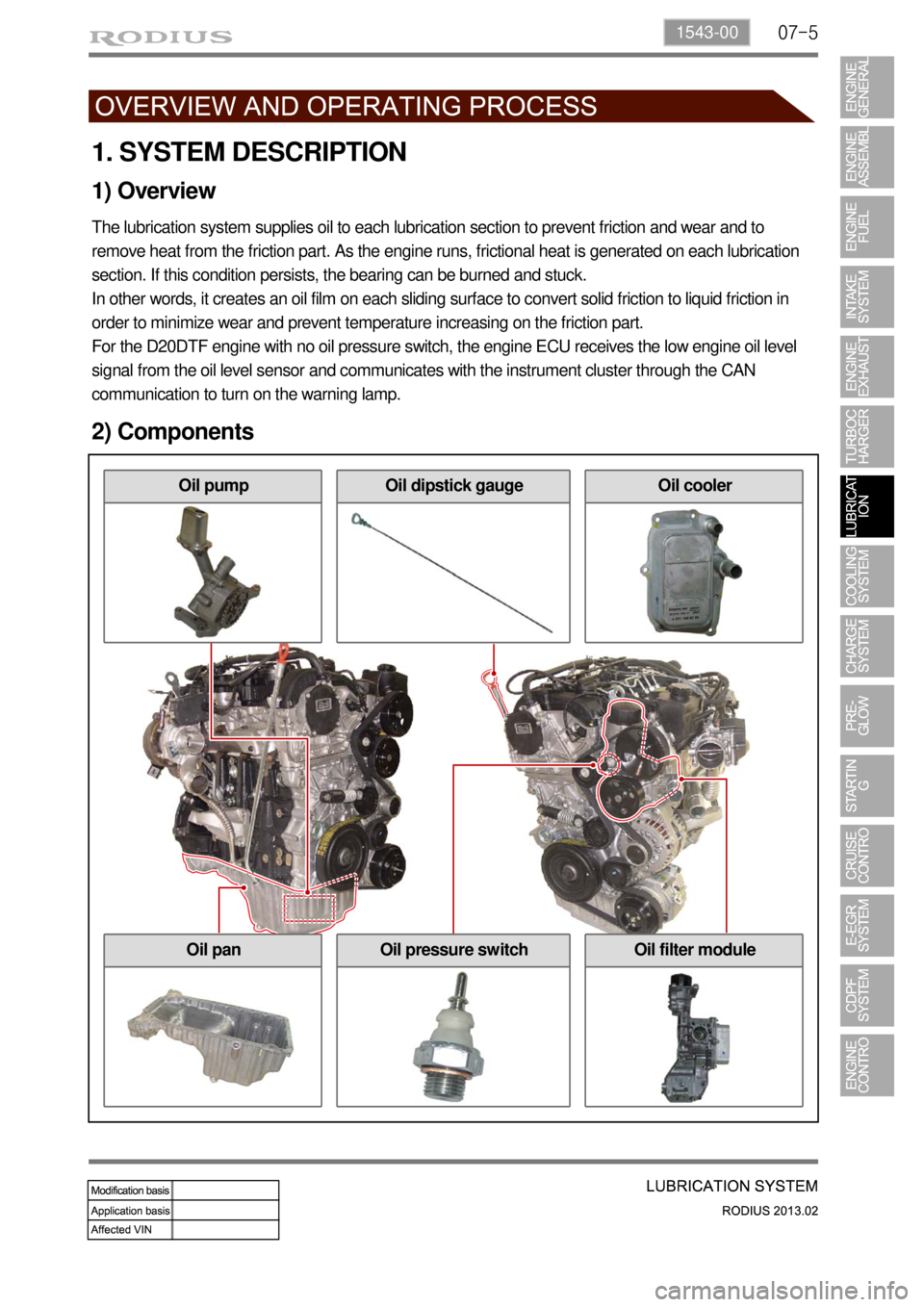
2) Components
Oil coolerOil dipstick gaugeOil pump
Oil filter moduleOil pressure switchOil pan
Page 273 of 796

08-4
2. INSPECTION
Possible Cause Action
Coolant level
is
too low- Leak from the radiator
- Leak from the coolant auxiliary tank
- Leak from the heater core- Change the radiator
- Change the coolant auxiliary tank
- Change the heater
- Leak from the coolant hose
connections
- Damaged coolant hose - Reconnect the hose or replace
the clamp
- Change the hose
- Leak from the water pump gasket
- Leak from the water pump internal
seal- Change the gasket
- Change the water pump
- Leak from the water inlet cap
- Leak from the thermostat housing- Change the water inlet cap
gasket
- Change the thermostat sealing
- Incorrect tightening torque of the
cylinder head bolts
- Damaged cylinder head gasket- Tighten the bolts to the specified
torque
- Change the cylinder head gasket
Coolant
temperature is
too high- Coolant leakage (Coolant level is low)
- Improper coolant mixture ratio
- Kinked coolant hose- Add coolant
- Check the coolant concentration
(Anti-freeze)
- Repair or replace the hose
- Defective thermostat
- Defective water pump
- Defective radiator
- Defective coolant auxiliary tank or tank
cap- Change the thermostat
- Change the water pump
- Change the radiator
- Change the coolant auxiliary tank
or tank cap
- Cracks on the cylinder block or
cylinder head
- Clogged coolant passages in the
cylinder block or cylinder head- Change cylinder block or cylinder
head
- Clean the coolant passage
- Clogged radiator core - Clean the radiator core
- Improper operation of cooling fan - Replace the cooling fan or repair
the related circuit
- Defective temperature sensor or
faulty wiring- Replace the sensor or repair the
related wiring
Coolant
temperature is
too low- Thermostat is stuck open - Change the thermostat
- Improper operation of cooling fan - Replace the cooling fan or repair
the related circuit
- Defective temperature sensor or faulty
wiring- Replace the sensor or repair the
related wiring
Page 274 of 796
08-51520-00
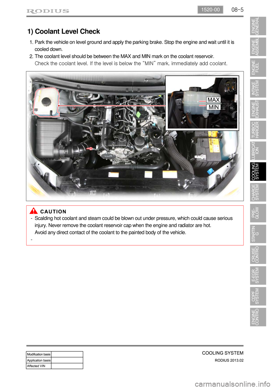
1) Coolant Level Check
Park the vehicle on level ground and apply the parking brake. Stop the engine and wait until it is
cooled down.
The coolant level should be between the MAX and MIN mark on the coolant reservoir.
Check the coolant level. If the level is below the “MIN” mark, immediately add coolant. 1.
2.
Scalding hot coolant and steam could be blown out under pressure, which could cause serious
injury. Never remove the coolant reservoir cap when the engine and radiator are hot.
Avoid any direct contact of the coolant to the painted body of the vehicle. -
-
Page 275 of 796
08-6
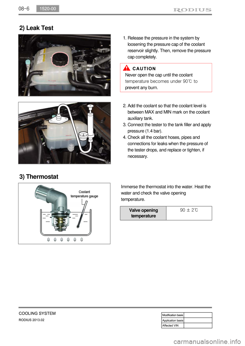
2) Leak Test
Release the pressure in the system by
loosening the pressure cap of the coolant
reservoir slightly. Then, remove the pressure
cap completely. 1.
Never open the cap until the coolant
temperature becomes under 90℃ to
prevent any burn.
Add the coolant so that the coolant level is
between MAX and MIN mark on the coolant
auxiliary tank.
Connect the tester to the tank filler and apply
pressure (1.4 bar).
Check all the coolant hoses, pipes and
connections for leaks when the pressure of
the tester drops, and replace or tighten, if
necessary. 2.
3.
4.
3) Thermostat
Immerse the thermostat into the water. Heat the
water and check the valve opening
temperature.
Valve opening
temperature 90 ± 2℃
Page 291 of 796
10-4
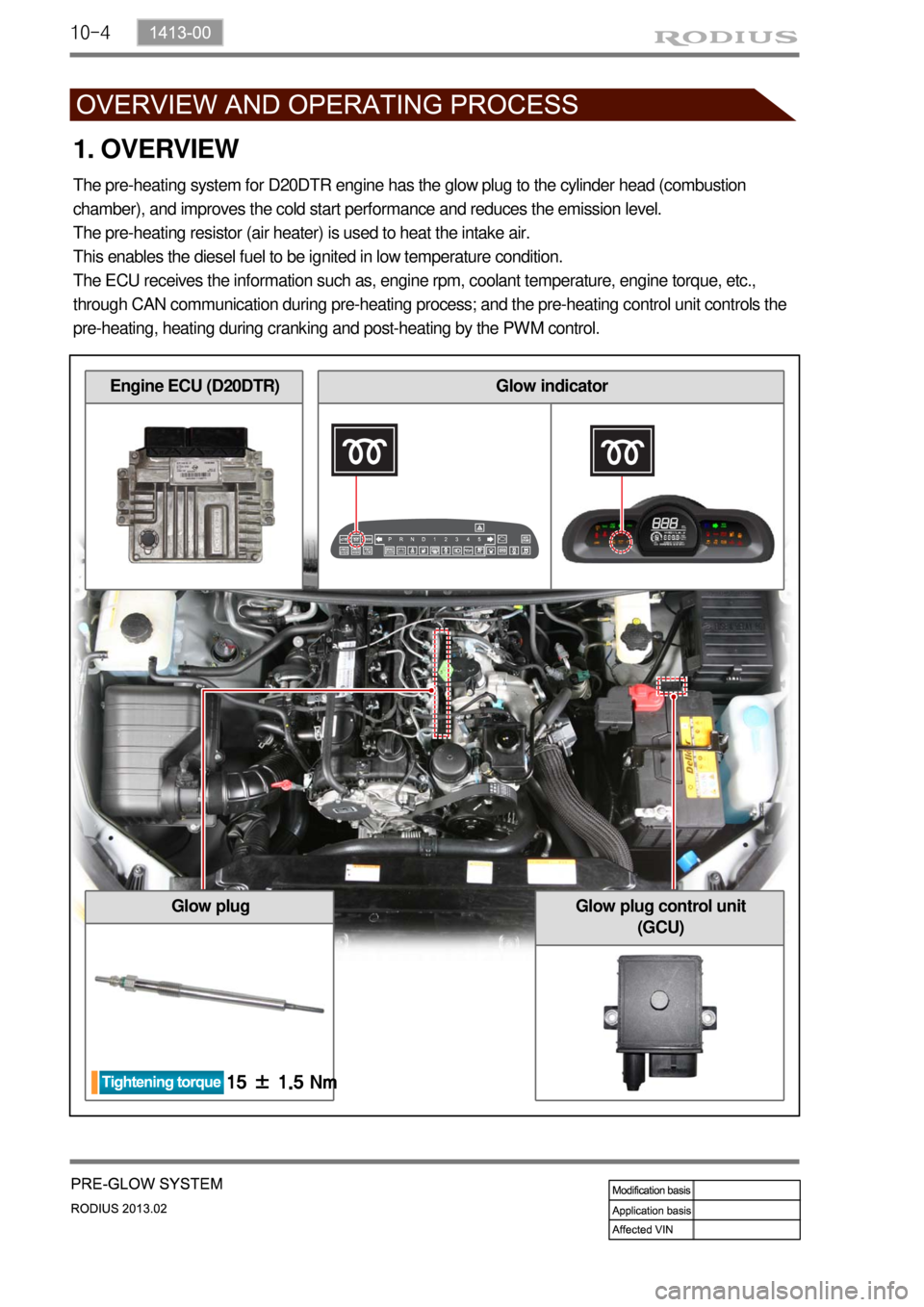
1. OVERVIEW
The pre-heating system for D20DTR engine has the glow plug to the cylinder head (combustion
chamber), and improves the cold start performance and reduces the emission level.
The pre-heating resistor (air heater) is used to heat the intake air.
This enables the diesel fuel to be ignited in low temperature condition.
The ECU receives the information such as, engine rpm, coolant temperature, engine torque, etc.,
through CAN communication during pre-heating process; and the pre-heating control unit controls the
pre-heating, heating during cranking and post-heating by the PWM control.
Glow plug
Engine ECU (D20DTR)Glow indicator
Glow plug control unit
(GCU)
Page 311 of 796

13-4
1. SYSTEM DESCRIPTION
1) Overview
The EGR (Electric-Exhaust Gas Recirculation) valve reduces the NOx emission level by recirculating
some of the exhaust gas to the intake system.
To meet Euro-V regulation, the capacity and response rate of E-EGR valve in D20DTR engine have
been greatly improved. The EGR cooler with high capacity reduces the Nox, and the bypass valve
reduces the CO and HC due to EGR gas before warming up.
Also, the engine ECU adjusts the E-EGR opening by using the air mass signal through HFM sensor. If
the exhaust gas gets into the intake manifold when the EGR valve is open, the amount of fresh air
through HFM sensor should be decresed.
Benefits of E-EGR valve ▶
Improved accuracy and response through electric control
Feedback function (Potentiometer)
Preventing chattering of EGR valve and improved durability
Self-cleaning function -
-
-
-
Page 315 of 796
14-32412-02
1. CAUTIONS
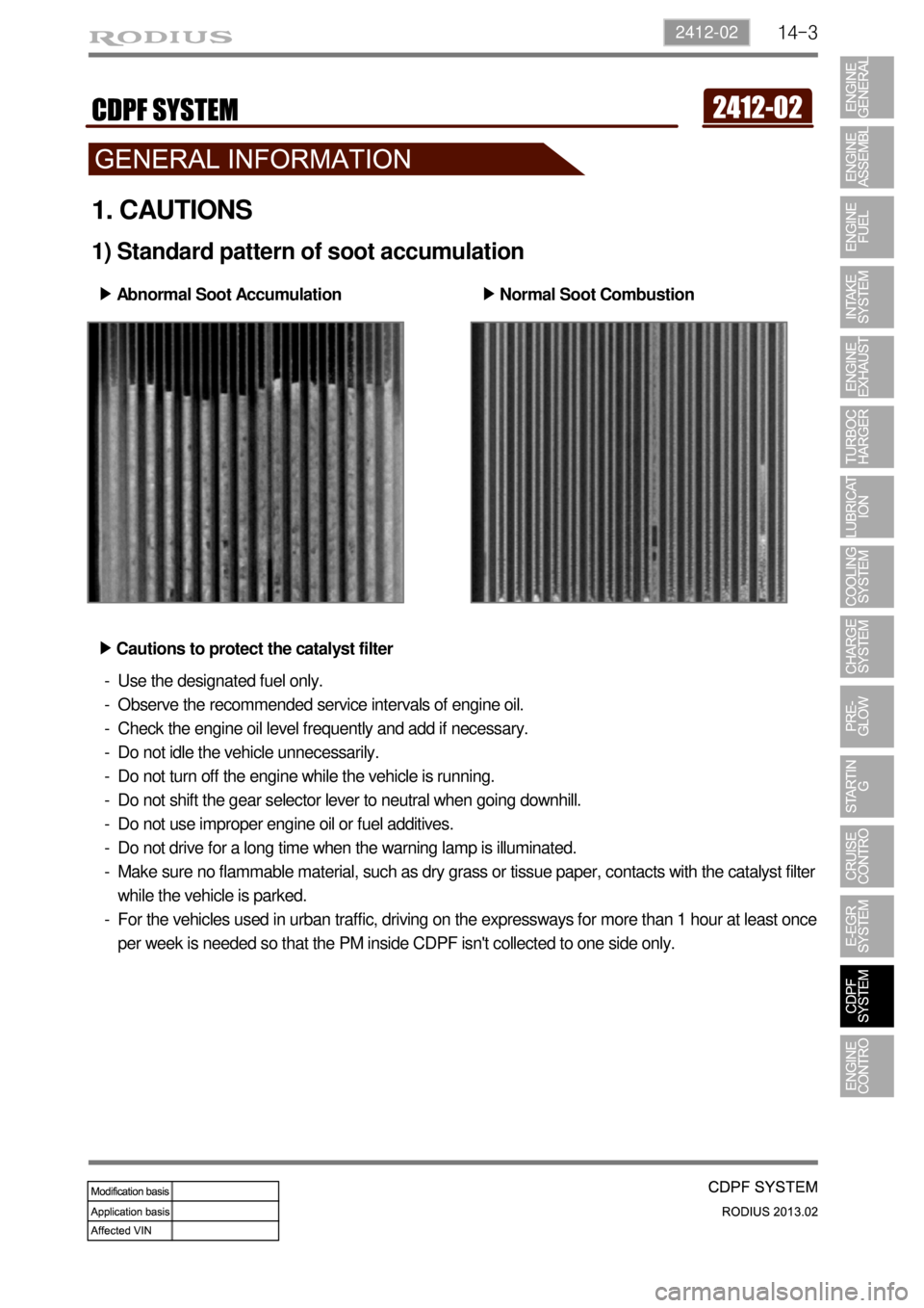
1) Standard pattern of soot accumulation
Abnormal Soot Accumulation ▶
Normal Soot Combustion ▶
Cautions to protect the catalyst filter ▶
Use the designated fuel only.
Observe the recommended service intervals of engine oil.
Check the engine oil level frequently and add if necessary.
Do not idle the vehicle unnecessarily.
Do not turn off the engine while the vehicle is running.
Do not shift the gear selector lever to neutral when going downhill.
Do not use improper engine oil or fuel additives.
Do not drive for a long time when the warning lamp is illuminated.
Make sure no flammable material, such as dry grass or tissue paper, contacts with the catalyst filter
while the vehicle is parked.
For the vehicles used in urban traffic, driving on the expressways for more than 1 hour at least once
per week is needed so that the PM inside CDPF isn't collected to one side only. -
-
-
-
-
-
-
-
-
-
Page 339 of 796
15-110000-00
2) ECU Control
(1) Function
a. ECU Function
ECU receives and analyzes signals from various sensors and then modifies those signals into
permissible voltage levels and analyzes to control respective actuators.
ECU microprocessor calculates injection period and injection timing proper for engine piston speed
and crankshaft angle based on input data and stored specific map to control the engine power and
emission gas.
Output signal of the ECU microprocessor drives pressure control valve to control the rail pressure and
activates injector solenoid valve to control the fuel injection period and injection timing; so controls
various actuators in response to engine changes. Auxiliary function of ECU has adopted to reduce
emission gas, improve fuel economy and enhance safety, comforts and conveniences. For example,
there are EGR, booster pressure control, autocruise (export only) and immobilizer and adopted CAN
communication to exchange data among electrical systems (automatic T/M and brake system) in the
vehicle fluently. And Scanner can be used to diagnose vehicle status and defectives.
Operating temperature range of ECU is normally -40 to +85°C and protected from factors like
oil, water and electromagnetism and there should be no mechanical shocks.
To control the fuel volume precisely under repeated injections, high current should be applied instantly
so there is injector drive circuit in the ECU to generate necessary current during injector drive stages.
Current control circuit divides current applying time (injection time) into full-in-current-phase and hold-
current-phase and then the injectors should work very correctly under every working condition.
b. Control Function
Controls by operating stages
To make optimum combustion under every operating stage, ECU should calculate proper injection
volume in each stage by considering various factors.
Starting injection volume control
During initial starting, injecting fuel volume will be calculated by function of temperature and engine
cranking speed. Starting injection continues from when the ignition switch is turned to ignition
position to till the engine reaches to allowable minimum speed.
Driving mode control
If the vehicle runs normally, fuel injection volume will be calculated by accelerator pedal travel and
engine rpm and the drive map will be used to match the drivers inputs with optimum engine power. -
-
-