instrument panel SUBARU BRZ 2023 Owners Manual
[x] Cancel search | Manufacturer: SUBARU, Model Year: 2023, Model line: BRZ, Model: SUBARU BRZ 2023Pages: 432, PDF Size: 16.56 MB
Page 9 of 432
How to Use This Owner’s Manual
3
Introduction
– CONTINUED –
Chapter 3: Instruments and Controls
This chapter informs you about the opera-
tion of instrument panel indicators and
how to use the instruments and other
switches.
Chapter 4: Climate Control
This chapter informs you how to operate
the climate control.
Chapter 5: Audio
This chapter informs you about your audio
system.
Chapter 6: Interior Equipment
This chapter informs you how to operate
interior equipment.
Chapter 7: Starting and Operating
This chapter informs you how to start and
operate your SUBARU.
Chapter 8: Driving Tips
This chapter informs you how to drive your
SUBARU in various conditions and
explains some safety tips on driving.
Chapter 9: In case of Emergency
This chapter informs you what to do if you
have a problem, such as a flat tire or
engine overheating.
Chapter 10: Appearance Care
This chapter informs you how to keep your
SUBARU looking good.
Chapter 11: Maintenance and Service This chapter informs you when you need
to take your SUBARU to the dealer for
scheduled maintenance and informs you
how to keep your SUBARU running prop-
erly.
Chapter 12: Specifications
This chapter informs you about the dimen-
sions and capacities of your SUBARU.
Chapter 13: Consumer Information and
Reporting Safety Defects
This chapter informs you about Tire infor-
mation, Uniform tire quality grading stan-
dards and Reporting safety defects.
Chapter 14: Index
This is an alphabetical listing of all that’s in
this manual. You can use it to quickly find
something you want to read.
For EyeSight system:
For details about the EyeSight system,
refer to the Owner’s Manual supplement
for the EyeSight system.
Depending on specifications, the vehicle
shown in the illustrations may differ from
your vehicle in terms of equipment.
■ Safety WarningsYou will find a number of WARNINGs,
CAUTIONs and NOTEs in this manual.
These safety warnings alert you to poten-
tial hazards that could result in injury to
you or others.
Please read these safety warnings as well
as all other portions of this manual care-
fully in order to gain a better under-
standing of how to use your SUBARU
vehicle safely.NOTEA NOTE gives information or sugges-
tions how to make better use of your
vehicle.
WARNING
A WARNING indicates a situation in
which serious injury or death could
result if the warning is ignored.
CAUTION
A CAUTION indicates a situation in
which injury or damage to your
vehicle, or both, could result if the
caution is ignored.
BRZ_U.book 3 ページ 2022年3月29日 火曜日 午後3時59分
Page 19 of 432
Illustrated Index
Illustrated Index
Exterior ..................................................................14
Interior ....................................................................16
Instrument Panel ...................................................19
Steering Wheel ......................................................20
Light Control and Wiper Control Levers/
Switches ..............................................................21
Combination Meter................................................22
U.S. Spec. Models (Normal mode) ............................... 22
U.S. Spec. Models (TRACK mo de) ............................... 23
Except U.S. Spec. Models (Normal mode)................... 24
Except U.S. Spec. Models (TRACK mode) . ................. 25
Warning and Indicator Lights ..............................26
BRZ_U.book 13 ページ 2022年3月29日 火曜日 午後3時59分
Page 25 of 432
Instrument Panel
19
Illustrated Index
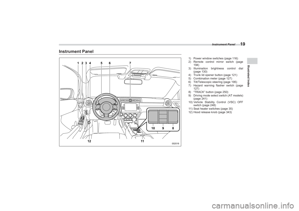
Instrument Panel
1
2
3
4
5
7
6
12
10
9
8
11
002018
1) Power window switches (page 116)
2) Remote control mirror switch (page
194)
3) Illumination brightness control dial (page 130)
4) Trunk lid opener button (page 121)
5) Combination meter (page 127)
6) Tilt/Telescopic steering (page 195)
7) Hazard warning flasher switch (page
127)
8) “TRACK” button (page 250)
9) Driving mode select switch (AT models)
(page 241)
10) Vehicle Stability Control (VSC) OFF
switch (page 248)
11) Seat heater switches (page 35)
12) Hood release knob (page 343)
BRZ_U.book 19 ページ 2022年3月29日 火曜日 午後3時59分
Page 38 of 432
Front Seats
32
WARNING
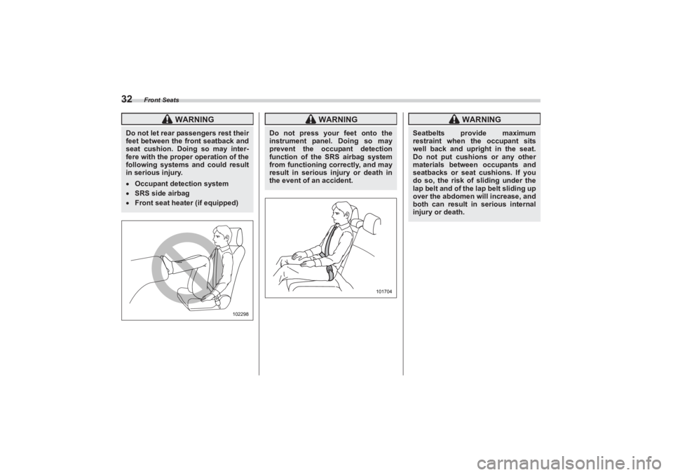
Do not let rear passengers rest their
feet between the front seatback and
seat cushion. Doing so may inter-
fere with the proper operation of the
following systems and could result
in serious injury. Occupant detection systemSRS side airbagFront seat heater (if equipped)
102298
WARNING
Do not press your feet onto the
instrument panel. Doing so may
prevent the occupant detection
function of the SRS airbag system
from functioning correctly, and may
result in serious injury or death in
the event of an accident.
101704
WARNING
Seatbelts provide maximum
restraint when the occupant sits
well back and upright in the seat.
Do not put cushions or any other
materials between occupants and
seatbacks or seat cushions. If you
do so, the risk of sliding under the
lap belt and of the lap belt sliding up
over the abdomen will increase, and
both can result in serious internal
injury or death.
BRZ_U.book 32 ページ 2022年3月29日 火曜日 午後3時59分
Page 69 of 432
SRS Airbag (Supplemental Restraint System Airbag)
63
Seat, Seatbelt and SRS Airbags1
– CONTINUED –
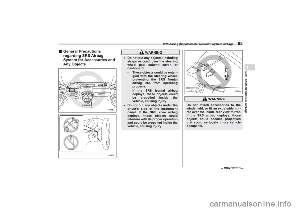
■General Precautions
regarding SRS Airbag
System for Accessories and
Any Objects
102683102218
WARNING
Do not put any objects (including
straps or cord) over the steering
wheel pad, column cover, or
dashboard.
- These objects could be entan- gled with the steering wheel,
preventing the SRS frontal
airbag, etc. from operating
properly.- If the SRS frontal airbag
deploys, these objects could
be propelled inside the
vehicle, causing injury.
Do not put any objects under the
driver’s side of the instrument
panel. If the SRS knee airbag
deploys, those objects could
interfere with its proper operation
and could be propelled inside the
vehicle, causing injury.
WARNING
Do not attach accessories to the
windshield, or fit an extra-wide mir-
ror over the inside rear view mirror.
If the SRS airbag deploys, those
objects could become projectiles
that could seriously injure vehicle
occupants.
101940
BRZ_U.book 63 ページ 2022年3月29日 火曜日 午後3時59分
Page 87 of 432
SRS Airbag (Supplemental Restraint System Airbag)
81
Seat, Seatbelt and SRS Airbags1
– CONTINUED –
▼SRS curtain airbag
Your vehicle is equipped with a SUBARU
SRS curtain airbag system that complies
with the Federal Motor Vehicle Safety
Standard (FMVSS) No. 226.
The SRS curtain airbag on each side of
the cabin is stored in the roof side
(between the front pillar and a point over
the rear seat). An “SRS AIRBAG” mark is
located at the top of each center pillar.
In a moderate to severe side impact colli-
sion, the SRS curtain airbag on the
impacted side of the vehicle deploys
between the occupant and the side
window and supplements the seatbelt by
reducing the impact on the occupant’s
head.
In a rollover, SRS curtain airbags on both
sides of the vehicle deploy between the
occupant and the side window and
supplement the seatbelt by reducing the
impact to the occupant’s head.
In an offset frontal collision, SRS curtain
airbags on both sides of the vehicle
deploy between the occupant and the side
window and supplement the seatbelt by
reducing the impact to the occupant’s
head and chest. ▼
Operation
The SRS side airbag and SRS curtain
airbag can function only when the ignition
switch is in the “ON” position.
The following airbags deploy inde-
pendently of each other since each has its
own impact sensor.
Driver’s SRS side airbag
Front passenger’s SRS side airbag
SRS curtain airbag (right-hand side)
SRS curtain airbag (left-hand side)
Therefore, they may not both deploy in the
same accident. Also, the SRS side airbag
and SRS curtain airbag deploys inde-
pendently of the driver’s and front
passenger’s SRS frontal airbags in the
steering wheel and instrument panel.
For the locations of the sensors and
control modules, refer to "Components"
P68.
▼ After deployment
After the deployment, the SRS side airbag
immediately starts to deflate. The time
required from detection of an impact to
deflation of an SRS side airbag after
deployment is shorter than the blink of an
eye.
The SRS curtain airbag remains inflated
for a while following deployment then
slowly deflates. The SRS side airbag and SRS curtain
airbag deploy even when no one occupies
the seat on the side on which an impact is
applied.
When the SRS side airbag and SRS
curtain airbag deploy, a sudden, fairly loud
inflation noise will be heard and some
smoke will be released. These occur-
rences are a normal result of the deploy-
ment. This smoke does not indicate a fire
in the vehicle.
▼ Example of the type of accident
The SRS side airbag and SRS curtain
airbag are designed as follows:
CAUTION
Do not touch the SRS side airbag
system components around the
front seat seatback with bare hands
right after deployment. Doing so
can cause burns because the com-
ponents can be very hot as a result
of deployment.After deployment, do not touch any
part of the SRS curtain airbag sys-
tem (from the front pillar to the part
of the roof side over the rear seat).
Doing so can cause burns because
the components can be very hot as
a result of deployment.
BRZ_U.book 81 ページ 2022年3月29日 火曜日 午後3時59分
Page 103 of 432
Keyless Access with Push-Button Start System
97
Keys and Doors2
– CONTINUED –
- When operating near a facility
where strong radio waves are trans-
mitted, such as a broadcast station
and power transmission lines.
- When products that transmit
radio waves are used, such as an
access key fob or a remote trans-
mitter key of another vehicle.
- When carrying the access key
fob of your vehicle together with the
access key fob or the remote trans-
mitter of another vehicle.
- When the access key fob is
placed near wireless communica-
tion equipment such as a cell phone.
- When the access key fob is
placed near a metallic object.
- When metallic accessories are
attached to the access key fob.
- When carrying the access key
fob with an elec tronic appliance
such as a laptop computer.
- When the battery of the access
key fob is discharged.
The access key fob is always
communicating with the vehicle and is
continuously using the battery.
Although the life of the battery varies
depending on the operating condi-
tions, it is approximately 1 to 2 years. If
the battery becomes fully discharged,
replace it with a new one.
If an access key fob is lost, it is
recommended that all of the remaining
access key fobs be reregistered. For
reregistration of an access key fob,
contact a SUBARU dealer.
For a spare access key fob, contact
a SUBARU dealer.
Up to 7 access key fobs can be
registered for one vehicle.
Do not leave the access key fob in
the storage spaces inside the vehicle,
such as the door pocket, dashboard or
inside the corner of the trunk. Vibra-
tions may damage the access key fob
or turn on the switch, possibly
resulting in a lockout.
After the vehicle battery is
discharged or replaced, initialization of
the steering lock system may be
required to start the engine. In this
case, perform the following procedure
to initialize the steering lock. (1) Turn the push -button ignition
switch to the “OFF” position. For
details, refer to "Switching Power
Status" P125.
(2) Open and close the driver’s door.
(3) Wait for approximately 10
seconds.
When the steering is locked, the initial-
ization is completed.
Do not leave the access key fob in
the following places. - On the instrument panel
- On the floor
- Inside the glove box
- Inside the door trim pocket
- On the rear seat
- On the rear shelf
- Inside the trunk
If you do, the following situations
may occur. - The access key fob is mistakenly
locked inside the vehicle.
- A false warning issues although
no malfunction actually occurs.
- No warning issues even when a
malfunction occurs.
■ Locking and Unlocking with
“Keyless Access” Entry
FunctionWhen the access key fob is carried within
the operating range, the doors, the fuel
filler lid can be locked/unlocked just by
touching the door handle.NOTEThe vehicle can also be locked/
unlocked with the remote keyless
entry system. For details, refer to
"Remote Keyless Entry System"
P109.
BRZ_U.book 97 ページ 2022年3月29日 火曜日 午後3時59分
Page 131 of 432
Push-Button Ignition Switch
125
Instruments and Controls3
– CONTINUED –
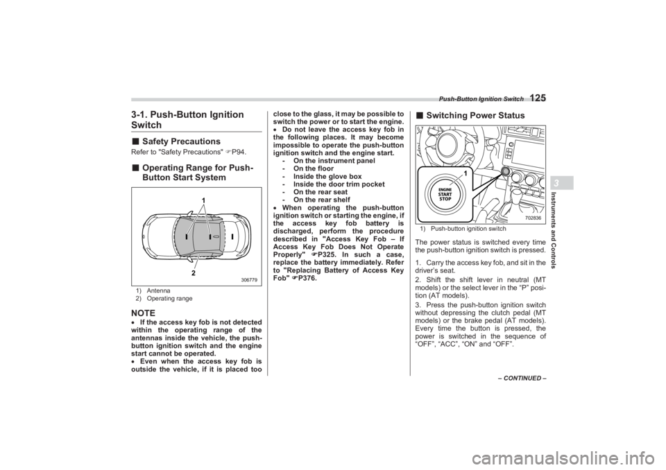
3-1. Push-Button Ignition Switch■Safety PrecautionsRefer to "Safety Precautions" P94.■ Operating Range for Push-
Button Start System1) Antenna
2) Operating rangeNOTEIf the access key fob is not detected
within the operating range of the
antennas inside the vehicle, the push-
button ignition switch and the engine
start cannot be operated.
Even when the access key fob is
outside the vehicle, if it is placed too close to the glass, it may be possible to
switch the power or to start the engine.
Do not leave the access key fob in
the following places. It may become
impossible to operate the push-button
ignition switch and the engine start. - On the instrument panel
- On the floor
- Inside the glove box
- Inside the door trim pocket
- On the rear seat
- On the rear shelf
When operating the push-button
ignition switch or starting the engine, if
the access key fob battery is
discharged, perform the procedure
described in "Access Key Fob – If
Access Key Fob Does Not Operate
Properly" P325. In such a case,
replace the battery immediately. Refer
to "Replacing Battery of Access Key
Fob" P376.
■ Switching Power Status1) Push-button ignition switchThe power status is switched every time
the push-button ignition switch is pressed.
1. Carry the access key fob, and sit in the
driver’s seat.
2. Shift the shift lever in neutral (MT
models) or the select lever in the “P” posi-
tion (AT models).
3. Press the push-button ignition switch
without depressing the clutch pedal (MT
models) or the brak e pedal (AT models).
Every time the button is pressed, the
power is switched in the sequence of
“OFF”, “ACC”, “ON” and “OFF”.
1
2
306779
1
702836
BRZ_U.book 125 ページ 2022年3月29日 火曜日 午後3時59分
Page 133 of 432
Hazard Warning Flasher
127
Instruments and Controls3
– CONTINUED –
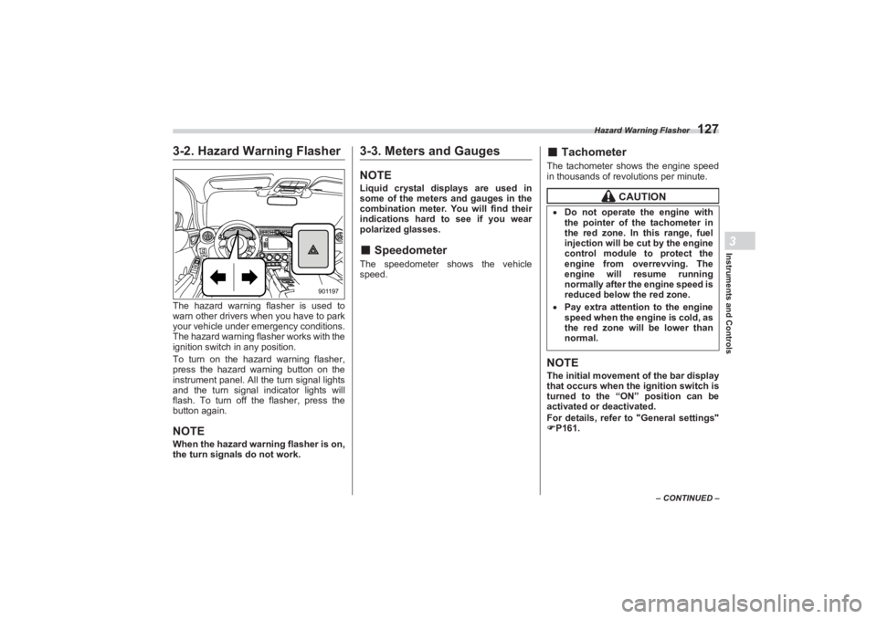
3-2. Hazard Warning FlasherThe hazard warning flasher is used to
warn other drivers when you have to park
your vehicle under emergency conditions.
The hazard warning fl asher works with the
ignition switch in any position.
To turn on the hazard warning flasher,
press the hazard warning button on the
instrument panel. All the turn signal lights
and the turn signal indicator lights will
flash. To turn off the flasher, press the
button again.NOTEWhen the hazard warning flasher is on,
the turn signals do not work.
3-3. Meters and GaugesNOTELiquid crystal displays are used in
some of the meters and gauges in the
combination meter. You will find their
indications hard to see if you wear
polarized glasses.■ SpeedometerThe speedometer shows the vehicle
speed.
■ TachometerThe tachometer shows the engine speed
in thousands of revolutions per minute.NOTEThe initial movement of the bar display
that occurs when the ignition switch is
turned to the “ON” position can be
activated or deactivated.
For details, refer to "General settings"
P161.
901197
CAUTION
Do not operate the engine with
the pointer of the tachometer in
the red zone. In this range, fuel
injection will be cut by the engine
control module to protect the
engine from overrevving. The
engine will resume running
normally after the engine speed is
reduced below the red zone. Pay extra attention to the engine
speed when the engine is cold, as
the red zone will be lower than
normal.
BRZ_U.book 127 ページ 2022年3月29日 火曜日 午後3時59分
Page 180 of 432
Light Control Switch
1743-10. Light Control SwitchThe light control switch operates when the
push-button ignition switch is in the “ACC”
or “ON” position.
Regardless of the pos ition of the light
control switch, the illuminated lights are
turned off when the push-button ignition
switch is turned off.NOTEThe light control switch can be oper-
ated (except auto on/off headlights),
even the push-button ignition switch
is turned off.
If the driver’s door is opened while the
headlights are illuminated under such conditions, a chirp sound will inform
the driver that the lights are illumi-
nated.
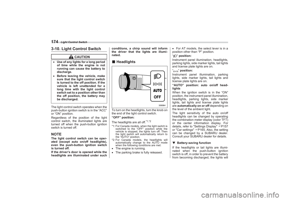
■ HeadlightsTo turn on the headlights, turn the knob on
the end of the light control switch.
“OFF” position:
The headlights are all off.
*1,*2
*1: For Canada models, when the light switch is
switched to the “OFF” position while the
vehicle is stopped, the lights turn off. Then
the light switch will automatically return to
the “AUTO” position.
*2: For Canada models, the headlights will automatically change to the AUTO mode
when the following conditions are met: The engine is running.
The parking brake is fully released.
For AT models, the select lever is in a
position other than “P” position.
“” position:
Instrument panel illumination, headlights,
parking lights, side marker lights, tail lights
and license plate lights are on.
“” position:
Instrument panel illumination, parking
lights, side marker lights, tail lights and
license plate lights are on.
“AUTO” position: auto on/off head-
lights
When the ignition switch is in the “ON”
position, the instrum ent panel illumination,
headlights, parking lights, side marker
lights, tail lights and license plate lights
are automatically on or off depending on
the level of the ambient light.
The light sensitivity of the auto on/off
headlights can be changed by operating
the combination meter display (color TFT)
or the center information display. For
details, refer to "Settings Display" P157
or "Car settings" P165. Also, the setting
can be changed by a SUBARU dealer.
Consult your SUBARU dealer for details.
▼ Battery-saving function
If the headlights or tail lights are illumi-
nated when the push-button ignition
switch is off, in order to prevent the battery
from becoming discharg ed, the lights will
CAUTION
Use of any lights for a long period
of time while the engine is not
running can cause the battery to
discharge. Before leaving the vehicle, make
sure that the light control switch
is turned to the off position. If the
vehicle is left unattended for a
long time with the light control
switch set to a position other than
the off position, the battery may
be discharged.
306964
BRZ_U.book 174 ページ 2022年3月29日 火曜日 午後3時59分