brake SUBARU CROSSTREK 2018 User Guide
[x] Cancel search | Manufacturer: SUBARU, Model Year: 2018, Model line: CROSSTREK, Model: SUBARU CROSSTREK 2018Pages: 474, PDF Size: 20.76 MB
Page 154 of 474
(159,1)
北米Model "A1320BE-C" EDITED: 2017/ 10/ 10
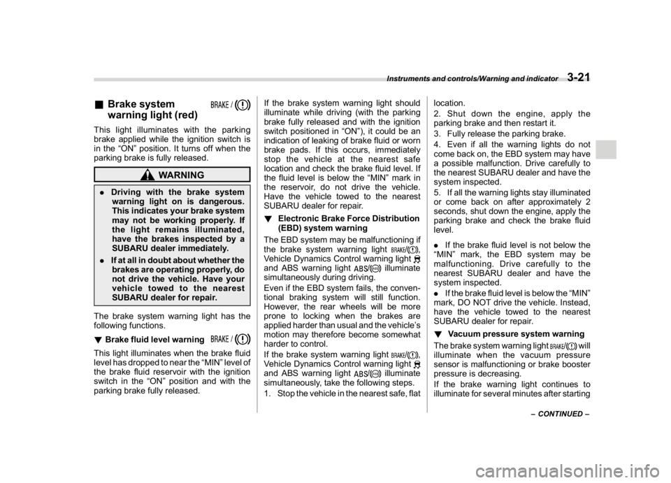
&Brake system
warning light (red)This light illuminates with the parking
brake applied while the ignition switch is
in the“ON”position. It turns off when the
parking brake is fully released.
WARNING
.Driving with the brake system
warning light on is dangerous.
This indicates your brake system
may not be working properly. If
the light remains illuminated,
have the brakes inspected by a
SUBARU dealer immediately.
.If at all in doubt about whether the
brakes are operating properly, do
not drive the vehicle. Have your
vehicle towed to the nearest
SUBARU dealer for repair.
The brake system warning light has the
following functions.
!Brake fluid level warningThis light illuminates when the brake fluid
level has dropped to near the“MIN”level of
the brake fluid reservoir with the ignition
switch in the“ON”position and with the
parking brake fully released.If the brake system warning light should
illuminate while driving (with the parking
brake fully released and with the ignition
switch positioned in“ON”), it could be an
indication of leaking of brake fluid or worn
brake pads. If this occurs, immediately
stop the vehicle at the nearest safe
location and check the brake fluid level. If
the fluid level is below the“MIN”mark in
the reservoir, do not drive the vehicle.
Have the vehicle towed to the nearest
SUBARU dealer for repair.
!Electronic Brake Force Distribution
(EBD) system warning
The EBD system may be malfunctioning if
the brake system warning light
/
,
Vehicle Dynamics Control warning light
and ABS warning light
/
illuminate
simultaneously during driving.
Even if the EBD system fails, the conven-
tional braking system will still function.
However, the rear wheels will be more
prone to locking when the brakes are
applied harder than usual and the vehicle’s
motion may therefore become somewhat
harder to control.
If the brake system warning light
/
,
Vehicle Dynamics Control warning light
and ABS warning light
/
illuminate
simultaneously, take the following steps.
1. Stop the vehicle in the nearest safe, flatlocation.
2. Shut down the engine, apply the
parking brake and then restart it.
3. Fully release the parking brake.
4. Even if all the warning lights do not
come back on, the EBD system may have
a possible malfunction. Drive carefully to
the nearest SUBARU dealer and have the
system inspected.
5. If all the warning lights stay illuminated
or come back on after approximately 2
seconds, shut down the engine, apply the
parking brake and check the brake fluid
level.
.If the brake fluid level is not below the
“MIN”mark, the EBD system may be
malfunctioning. Drive carefully to the
nearest SUBARU dealer and have the
system inspected.
.If the brake fluid level is below the“MIN”
mark, DO NOT drive the vehicle. Instead,
have the vehicle towed to the nearest
SUBARU dealer for repair.
!Vacuum pressure system warning
The brake system warning light
/
will
illuminate when the vacuum pressure
sensor is malfunctioning or brake booster
pressure is decreasing.
If the brake warning light continues to
illuminate for several minutes after starting
–CONTINUED–
Instruments and controls/Warning and indicator
3-21
3
Page 156 of 474
(161,1)
北米Model "A1320BE-C" EDITED: 2017/ 10/ 10
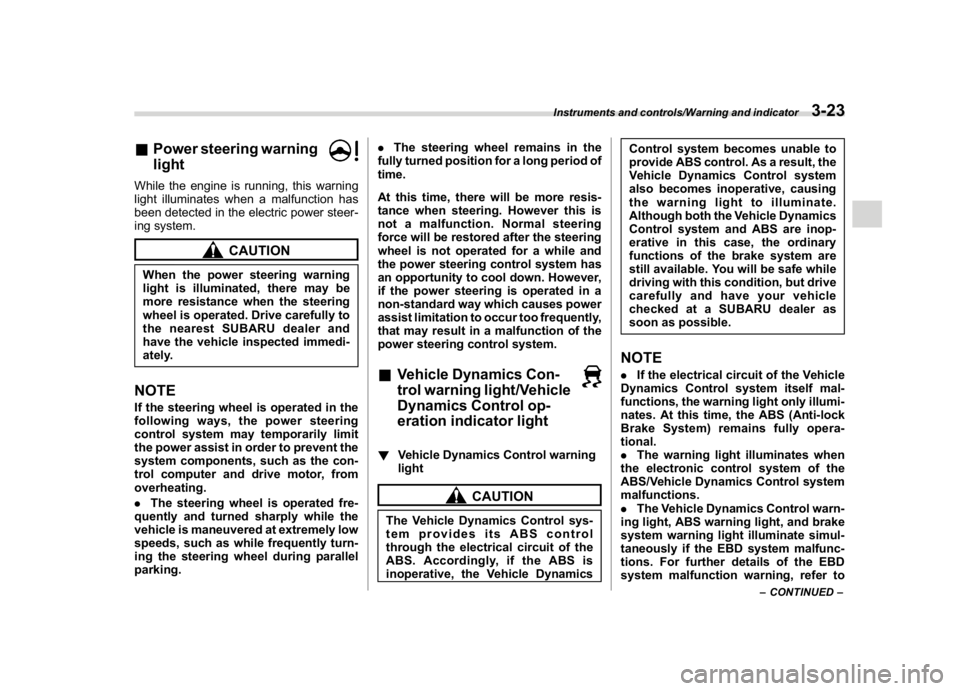
&Power steering warning
lightWhile the engine is running, this warning
light illuminates when a malfunction has
been detected in the electric power steer-
ing system.
CAUTION
When the power steering warning
light is illuminated, there may be
more resistance when the steering
wheel is operated. Drive carefully to
the nearest SUBARU dealer and
have the vehicle inspected immedi-
ately.NOTEIf the steering wheel is operated in the
following ways, the power steering
control system may temporarily limit
the power assist in order to prevent the
system components, such as the con-
trol computer and drive motor, from
overheating.
.The steering wheel is operated fre-
quently and turned sharply while the
vehicle is maneuvered at extremely low
speeds, such as while frequently turn-
ing the steering wheel during parallel
parking..The steering wheel remains in the
fully turned position for a long period of
time.
At this time, there will be more resis-
tance when steering. However this is
not a malfunction. Normal steering
force will be restored after the steering
wheel is not operated for a while and
the power steering control system has
an opportunity to cool down. However,
if the power steering is operated in a
non-standard way which causes power
assist limitation to occur too frequently,
that may result in a malfunction of the
power steering control system.
&Vehicle Dynamics Con-
trol warning light/Vehicle
Dynamics Control op-
eration indicator light!Vehicle Dynamics Control warning
light
CAUTION
The Vehicle Dynamics Control sys-
tem provides its ABS control
through the electrical circuit of the
ABS. Accordingly, if the ABS is
inoperative, the Vehicle DynamicsControl system becomes unable to
provide ABS control. As a result, the
Vehicle Dynamics Control system
also becomes inoperative, causing
the warning light to illuminate.
Although both the Vehicle Dynamics
Control system and ABS are inop-
erative in this case, the ordinary
functions of the brake system are
still available. You will be safe while
driving with this condition, but drive
carefully and have your vehicle
checked at a SUBARU dealer as
soon as possible.
NOTE.If the electrical circuit of the Vehicle
Dynamics Control system itself mal-
functions, the warning light only illumi-
nates. At this time, the ABS (Anti-lock
BrakeSystem)remainsfullyopera-
tional.
.The warning light illuminates when
the electronic control system of the
ABS/Vehicle Dynamics Control system
malfunctions.
.The Vehicle Dynamics Control warn-
ing light, ABS warning light, and brake
system warning light illuminate simul-
taneously if the EBD system malfunc-
tions. For further details of the EBD
system malfunction warning, refer to
–CONTINUED–
Instruments and controls/Warning and indicator
3-23
3
Page 157 of 474
(162,1)
北米Model "A1320BE-C" EDITED: 2017/ 10/ 10
“Electronic Brake Force Distribution
(EBD) system warning”F3-21.
The Vehicle Dynamics Control system is
probably inoperative under any of the
following conditions. Have your vehicle
checked at a SUBARU dealer immedi-
ately.
.The warning light does not illuminate
when the ignition switch is turned to the
“ON”position.
.The warning light illuminates while the
vehicle is running.NOTEIf the warning light behavior is as
described in the following examples,
the Vehicle Dynamics Control system
may be considered normal.
.The warning light illuminates when
the ignition switch is turned to the“ON”
position and turns off approximately 2
seconds after the engine has started.
.The warning light illuminates right
after the engine is started but turns off
immediately, remaining off.
.The warning light illuminates after
the engine has started and turns off
while the vehicle is subsequently being
driven.
.The warning light illuminates during
driving, but it turns off immediately and
remains off..The warning light illuminates when
the engine has stalled and continues to
illuminate after the engine has been
restarted. However, it will turn off once
the vehicle starts moving.
!Vehicle Dynamics Control operation
indicator light
The indicator light flashes during activation
of the skid suppression function and during
activation of the traction control function.
NOTE.The light may remain illuminated for
a short period of time after the engine
has been started, especially in cold
weather. This does not indicate the
existence of a problem. The light
should turn off as soon as the engine
has warmed up.
.The indicator light illuminates when
the engine has developed a problem
and the CHECK ENGINE warning light/
malfunction indicator light is on.
The Vehicle Dynamics Control system is
probably malfunctioning under the follow-
ing condition. Have your vehicle checked
at a SUBARU dealer as soon as possible.
.The light does not turn off even after the
lapse of several minutes (the engine has
warmed up) after the engine has started.
&Vehicle Dynamics Con-
trol OFF indicator lightThe light illuminates when the Vehicle
Dynamics Control OFF switch is pressed
to deactivate the Vehicle Dynamics Con-
trol system.
The Vehicle Dynamics Control system is
probably malfunctioning under any of the
following conditions. Have your vehicle
checked at a SUBARU dealer immedi-
ately.
.The light does not illuminate when the
ignition switch is turned to the“ON”
position.
.The light does not turn off even once
several seconds have elapsed after the
ignition switch has been turned to the“ON”
position.
Instruments and controls/Warning and indicator
3-24
Page 161 of 474
(166,1)
北米Model "A1320BE-C" EDITED: 2017/ 10/ 10
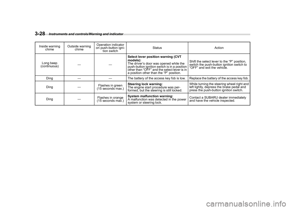
Inside warning
chimeOutside warning
chimeOperation indicator
on push-button igni-
tion switchStatus Action
Long beep
(continuous)——Select lever position warning (CVT
models):
The driver’s door was opened while the
push-button ignition switch is in a position
other than“OFF”and the select lever is in
a position other than the“P”position.Shift the select lever to the“P”position,
switch the push-button ignition switch to
“OFF”and exit the vehicle.
Ding——The battery of the access key fob is low. Replace the battery of the access key fob.
Ding—Flashes in green
(15 seconds max.)Steering lock warning:
The engine start procedure was per-
formed, but the steering is still locked.While turning the steering wheel right and
left lightly, depress the brake pedal and
press the push-button ignition switch.
Ding—Flashes in orange
(15 seconds max.)System malfunction warning:
A malfunction was detected in the power
system or steering lock.Contact a SUBARU dealer immediately
and have the vehicle inspected.
Instruments and controls/Warning and indicator
3-28
Page 205 of 474
(210,1)
北米Model "A1320BE-C" EDITED: 2017/ 10/ 10
–When the headlights of an oncom-
ing vehicle or the tail lights of a vehicle
ahead illuminate on only one side.
–When the oncoming vehicle or
vehicle ahead is a motorcycle.
–Conditions of a road (slope, curve,
road surface, etc.).
–Number of passengers and weight
of loaded cargo.
–Limitation of the detection ability of
the stereo camera.
&Daytime running light system
WARNING
When the daytime running lights are
illuminated, the tail lights do not
illuminate. When it becomes dark
outside, turn the light switch to the
“
”position to illuminate the head-
lights and tail lights. This will im-
prove visibility and allow other dri-
vers to see your vehicle more easily.
The daytime running lights will automati-
cally illuminate when the following condi-
tions are fulfilled.
.The engine is running.
.The parking brake is fully released.
.The light control switch is in the“AUTO”
(if equipped),“
”or off position..For CVT models, the select lever is in a
position other than the“P”position.
NOTEWhen the light switch is in the“
”
position, the instrument panel illumina-
tion, front side marker lights, tail lights
and license plate lights are also illumi-
nated.
Steering Responsive Head-
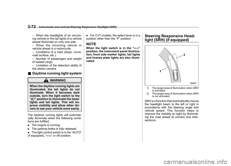
light (SRH) (if equipped)1) The target area of illumination when SRH
is activated
2) The target area of illumination when SRH
is not activatedSRH is a function that automatically moves
the headlight beam to the left or right in
accordance with the steering angle and
vehicle speed. This function helps to
improve the visibility at night by illuminat-
ing the road ahead at corners and inter-
sections.
Instruments and controls/Steering Responsive Headlight (SRH)
3-72
Page 251 of 474
(258,1)
北米Model "A1320BE-C" EDITED: 2017/ 10/ 10
.Use only electrical appliances
which are designed for 12V DC.
The maximum power rating of an
appliance that can be connected
is 120W. Do not use an appliance
which exceeds the indicated wat-
tage for each outlet.
.When using appliances con-
nected to two outlets simulta-
neously, the total power con-
sumed by them must not exceed
120W. Overloading the accessory
power outlet can cause a short
circuit. Do not use double adap-
ters or more than one electrical
appliance.
.If the plug on your electric appli-
ance is either too loose or too
tight for the accessory power
outlet, this can result in a poor
contact or cause the plug to get
stuck. Only use plugs that fit
properly.
.Use of an electric appliance in the
accessory power outlet for a long
period of time while the engine is
not running can cause battery
discharge.
.Before driving your vehicle, make
sure that the plug and the cord on
your electrical appliance will notinterfere with your shifting gears
and operating the accelerator
and brake pedals. If they do, do
not use the electrical appliance
while driving.
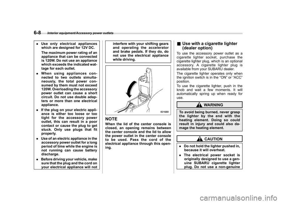
NOTEWhen the lid of the center console is
closed, an opening remains between
the center console and the lid to allow
the power outlet in the center console
to be used. Pass the cord of the
electrical appliance through this open-
ing.
&Use with a cigarette lighter
(dealer option)To use the accessory power outlet as a
cigarette lighter socket, purchase the
cigarette lighter plug, which is an optional
accessory. A cigarette lighter plug is
available from your SUBARU dealer.
The cigarette lighter operates only when
the ignition switch is in the“ON”or“ACC”
position.
To use the cigarette lighter, push in the
knob and wait a few moments. It will
automatically spring up when ready for
use.
WARNING
To avoid being burned, never grasp
the lighter by the end with the
heating element. Doing so could
result in injury and could also da-
mage the heating element.
CAUTION
.Do not hold the lighter pushed in,
because it will overheat.
.The electrical power socket is
originally designed to use a gen-
uine SUBARU cigarette lighter
plug. Do not use a non-genuine
Interior equipment/Accessory power outlets
6-8
Page 258 of 474
(267,1)
北米Model "A1320BE-C" EDITED: 2017/ 10/ 10
Fuel..........................................................................7-3
Fuel requirements.................................................. 7-3
Fuel filler lid and cap............................................. 7-4
State emission testing (U.S.only).........................7-7
Preparing to drive...................................................7-8
Starting and stopping the engine
(models without push-button startsystem)...... 7-9
Starting engine...................................................... 7-9
Stopping the engine.............................................. 7-11
Starting and stopping engine
(models with push-button startsystem).......... 7-11
Safety precautions................................................ 7-11
Operating range for push-button start system....... 7-11
Starting engine..................................................... 7-11
Stopping engine....................................................7-13
When access key fob does not operate properly ... 7-14
Remote engine start system(dealer option)...... 7-14
Remote engine starter transceiver (fob) .................7-15
Alternate operation method for models with
“keyless access with push-button start
system”..............................................................7-18
Entering the vehicle while it is running via
remote start........................................................7-18
Entering the vehicle following remote engine
start shutdown....................................................7-19
Pre-heating or pre-cooling the interior of
the vehicle..........................................................7-19
Remote transmitter program
(Remote engine starter transceiver).....................7-19
System maintenance.............................................7-19
Certification for remote engine starter...................7-21
Manual transmission............................................7-21
Shifting speeds....................................................7-22
Driving tips...........................................................7-23
Continuously variable transmission...................7-24
Continuously variable transmission features.........7-24
Select lever..........................................................7-25
Selection of manual mode (if equipped)................7-26
Selection of“L”(if equipped) ................................7-28
Shift lock function................................................7-28
Driving tips...........................................................7-30
Power steering......................................................7-30
Power steering warning light ................................7-30
Power steering system features............................7-30
Braking..................................................................7-31
Braking tips..........................................................7-31
Brake system.......................................................7-31
Disc brake pad wear warning indicators................7-32
ABS (Anti-lock BrakeSystem).............................7-33
ABS self-check.....................................................7-33
ABS warning light.................................................7-33
Electronic Brake Force Distribution (EBD)
system................................................................7-34
Steps to take if EBD system malfunctions .............7-34
Vehicle Dynamics Controlsystem......................7-35
Safety precautions................................................7-35
System features....................................................7-36
Vehicle Dynamics Control system monitor ............7-37
Vehicle Dynamics Control OFF switch...................7-37
X-mode (if equipped)............................................7-38
To activate/deactivate the X-mode.........................7-39
Starting and operating
7
Page 259 of 474
(268,1)
北米Model "A1320BE-C" EDITED: 2017/ 10/ 10
Hill descent control function.................................7-40
Tire pressure monitoring system (TPMS)
(U.S.-spec. models)............................................7-41
Parking your vehicle.............................................7-43
Parking brake.......................................................7-43
Parking tips..........................................................7-43
Hill start assistsystem.........................................7-45
To activate/deactivate the Hill start assist
system................................................................7-46
Hill start assist warning light/Hill start assist
OFF indicator light..............................................7-47
Cruise control (ifequipped).................................7-48
To set cruise control.............................................7-48
To temporarily cancel the cruise control................7-49
To turn off the cruise control.................................7-50
To change the cruising speed...............................7-50
Cruise control indicator light.................................7-52
Cruise control set indicator light...........................7-52
BSD/RCTA (ifequipped).......................................7-52
System features....................................................7-52
System operation.................................................7-55
BSD/RCTA approach indicator light/warning
buzzer...............................................................7-56
BSD/RCTA warning indicator................................7-58
BSD/RCTA OFF switch..........................................7-59
Certification for the BSD/RCTA.............................7-60
Handling of radar sensors....................................7-60
Reverse Automatic Braking System
(if equipped).......................................................7-61
Reverse Automatic Braking System overview........7-62
Operating conditions............................................7-62
Reverse Automatic Braking System operation .......7-65
Canceling the Reverse Automatic Braking
system operation...............................................7-67
Reverse Automatic Braking system ON/OFF
setting...............................................................7-68
RAB warning indicator..........................................7-69
Handling of the sonar sensors..............................7-69
Starting and operating
Page 265 of 474
(274,1)
北米Model "A1320BE-C" EDITED: 2017/ 10/ 10
on a dynamometer, tell your emission
inspector not to place your SUBARU
AWD vehicle on a two-wheel dynam-
ometer.Otherwise, serious transmis-
sion damage will result.
The U.S. Environmental Protection
Agency (EPA) and states using two-wheel
dynamometers in their emission testing
program have EXEMPTED SUBARU
AWD vehicles from the portion of the
testing program that involves a two-wheel
dynamometer. There are some states that
use four-wheel dynamometers in their
testing program. When properly used, this
equipment should not damage a SUBARU
AWD vehicle.
Under no circumstances should the rear
wheels be jacked off the ground, nor
should the driveshaft be disconnected in
an attempt to bypass AWD for state
emission testing. An AWD vehicle must
be tested using an AWD dynamometer
with all 4 wheels driven and loaded.
Preparing to driveYou should perform the following checks
and adjustments every day before you
start driving.
1. Check that all windows, mirrors, and
lights are clean and unobstructed.
2. Check the appearance and condition
of the tires. Also check tires for proper
inflation.
3. Look under the vehicle for any sign of
leaks.
4. Check that no small animals enter the
engine compartment.
5. Check that the hood and rear gate are
fully closed.
6. Check the adjustment of the seat.
7. Check the adjustment of the inside and
outside mirrors.
8. Fasten your seatbelt. Check that your
passengers have fastened their seatbelts.
9. Check the operation of the warning
and indicator lights when the ignition
switch is turned to the“ON”position.
10. Check the gauges, indicator and warn-
ing lights after starting the engine.
CAUTION
Trapping small animals in the cool-
ing fan and belts of the engine may
result in a malfunction. Check that
no small animal enters the engine
compartment and under the vehicle
before starting the engine.NOTE.Engine oil, engine coolant, brake
fluid, washer fluid and other fluid levels
should be checked daily, weekly or at
fuel stops.
.When towing a trailer, refer to“Trai-
ler hitch (dealer option)”F8-14
Starting and operating/Preparing to drive
7-8
Page 267 of 474
(276,1)
北米Model "A1320BE-C" EDITED: 2017/ 10/ 10
!MT models
1. Apply the parking brake.
2. Turn off unnecessary lights and acces-
sories.
3. Depress the clutch pedal to the floor
and shift the shift lever into neutral. Hold
the clutch pedal to the floor while starting
the engine.
The starter motor will only operate when
the clutch pedal is depressed fully to the
floor.
4. Turn the ignition switch to the“ON”
position and check the operation of the
warning and indicator lights. Refer to
“Warning and indicator”F3-12.
5. Turn the ignition switch to the“START”
positionwithoutdepressing the accelera-
tor pedal. Release the key immediately
after the engine has started.
If the engine does not start, try the
following procedure.
(1) Turn the ignition switch to the
“LOCK”/“OFF”position and wait for at
least 10 seconds. After checking that
the parking brake is firmly set, turn the
ignition switch to the“START”position
while depressing the accelerator pedal
slightly (approximately a quarter of the
full stroke). Release the accelerator
pedal as soon as the engine starts.
(2) If this fails to start the engine, turnthe ignition switch back to the“LOCK”/
“OFF”position and wait for at least 10
seconds. Then fully depress the accel-
erator pedal and turn the ignition
switch to the“START”position. If the
engine starts, quickly release the ac-
celerator pedal.
(3) If this fails to start the engine, turn
the ignition switch again to the“LOCK”/
“OFF”position. After waiting for 10
seconds or longer, turn the ignition
switch to the“START”position without
depressing the accelerator pedal.
(4) If the engine still fails to start,
contact your nearest SUBARU dealer
for assistance.
6. Confirm that all warning and indicator
lights have turned off after the engine has
started. The fuel injection system auto-
matically lowers the idle speed as the
engine warms up.
!CVT models
1. Apply the parking brake.
2. Turn off unnecessary lights and acces-
sories.
3. Shift the select lever to the“P”or“N”
position (preferably the“P”position).
The starter motor will only operate when
the select lever is at the“
P”or“N”position.
4. Turn the ignition switch to the“ON”position and check the operation of the
warning and indicator lights. Refer to
“Warning and indicator”F3-12.
5. Turn the ignition switch to the“START”
positionwithoutdepressing the accelera-
tor pedal. Release the key immediately
after the engine has started.
If the engine does not start, try the
following procedure.
(1) Turn the ignition switch to the
“LOCK”/“OFF”position and wait for at
least 10 seconds. After checking that
the parking brake is firmly set, turn the
ignition switch to the“START”position
while depressing the accelerator pedal
slightly (approximately a quarter of the
full stroke). Release the accelerator
pedal as soon as the engine starts.
(2) If this fails to start the engine, turn
the ignition switch back to the“LOCK”/
“OFF”position and wait for at least 10
seconds. Then fully depress the accel-
erator pedal and turn the ignition
switch to the“START”position. If the
engine starts, quickly release the ac-
celerator pedal.
(3) If this fails to start the engine, turn
the ignition switch again to the“LOCK”/
“OFF”position. After waiting for 10
seconds or longer, turn the ignition
switch to the“START”position without
depressing the accelerator pedal.
Starting and operating/Starting and stopping the engine (models without push-button start system)
7-10