position sensor SUBARU CROSSTREK 2018 User Guide
[x] Cancel search | Manufacturer: SUBARU, Model Year: 2018, Model line: CROSSTREK, Model: SUBARU CROSSTREK 2018Pages: 474, PDF Size: 20.76 MB
Page 159 of 474
(164,1)
北米Model "A1320BE-C" EDITED: 2017/ 10/ 10
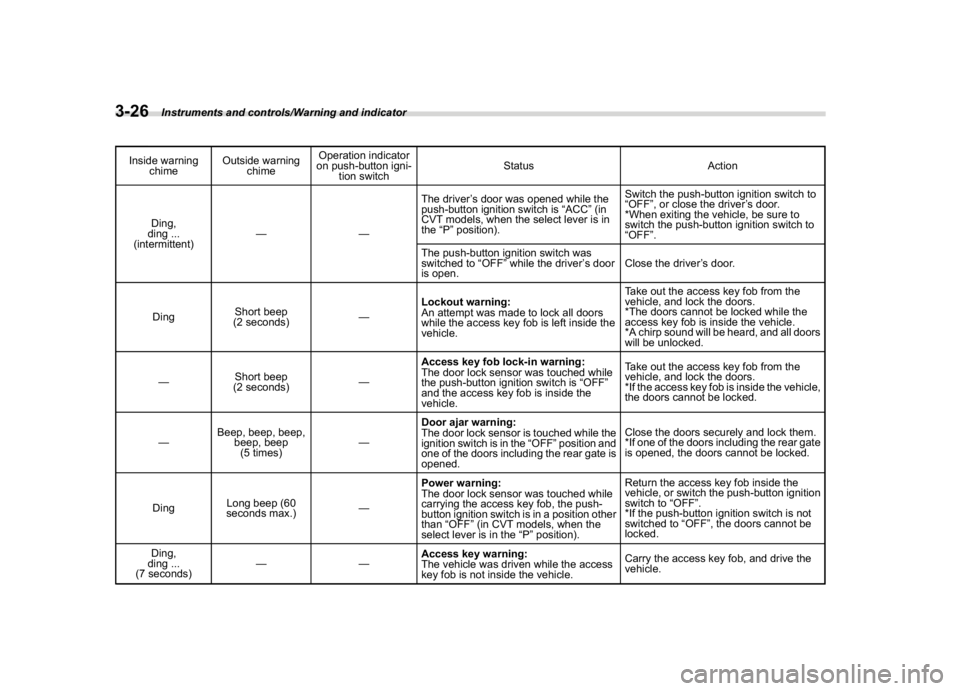
Inside warning
chimeOutside warning
chimeOperation indicator
on push-button igni-
tion switchStatus Action
Ding,
ding ...
(intermittent)——The driver’s door was opened while the
push-button ignition switch is“ACC”(in
CVT models, when the select lever is in
the“P”position).Switch the push-button ignition switch to
“OFF”, or close the driver’s door.
*When exiting the vehicle, be sure to
switch the push-button ignition switch to
“OFF”.
The push-button ignition switch was
switched to“OFF”while the driver’s door
is open.Close the driver’s door.
DingShort beep
(2 seconds)—Lockout warning:
An attempt was made to lock all doors
while the access key fob is left inside the
vehicle.Take out the access key fob from the
vehicle, and lock the doors.
*The doors cannot be locked while the
access key fob is inside the vehicle.
*A chirp sound will be heard, and all doors
will be unlocked.
—Short beep
(2 seconds)—Access key fob lock-in warning:
The door lock sensor was touched while
the push-button ignition switch is“OFF”
and the access key fob is inside the
vehicle.Take out the access key fob from the
vehicle, and lock the doors.
*If the access key fob is inside the vehicle,
the doors cannot be locked.
—Beep, beep, beep,
beep, beep
(5 times)—Door ajar warning:
The door lock sensor is touched while the
ignition switch is in the“OFF”position and
one of the doors including the rear gate is
opened.Close the doors securely and lock them.
*If one of the doors including the rear gate
is opened, the doors cannot be locked.
DingLong beep (60
seconds max.)—
Power warning:
The door lock sensor was touched while
carrying the access key fob, the push-
button ignition switch is in a position other
than“OFF”(in CVT models, when the
select lever is in the“P”position).Return the access key fob inside the
vehicle, or switch the push-button ignition
switch to“OFF”.
*If the push-button ignition switch is not
switched to“OFF”, the doors cannot be
locked.
Ding,
ding ...
(7 seconds)——Access key warning:
The vehicle was driven while the access
key fob is not inside the vehicle.Carry the access key fob, and drive the
vehicle.
Instruments and controls/Warning and indicator
3-26
Page 175 of 474
(180,1)
北米Model "A1320BE-C" EDITED: 2017/ 10/ 10
doors to unlock simultaneously when
accessing from the cargo area.
!Defogger
Sets and customizes the operation of the
defogger.
!Interior Light
Sets and customizes the interior light off
delay timer.
!Auto Light Sensor (if equipped)
Sets and customizes the sensitivity of the
auto light sensor.
!Welcome Lighting (if equipped)
Sets the leaving time and approaching
time.
.Approaching time set
Sets the illumination time of the headlights
that illuminate when you approach the
vehicle.
.Leaving time set
Sets the time until the headlights turn off
when you have moved away from the
vehicle.
!One-touch lane changer
Sets the one-touch lane changer on/off.!Default Settings
Select“Ye s”to use the menu screen to
restore customized settings to the factory
default settings. Select“No”to return to the
previous screen without restoring to the
factory default settings.
Multi-function display (black
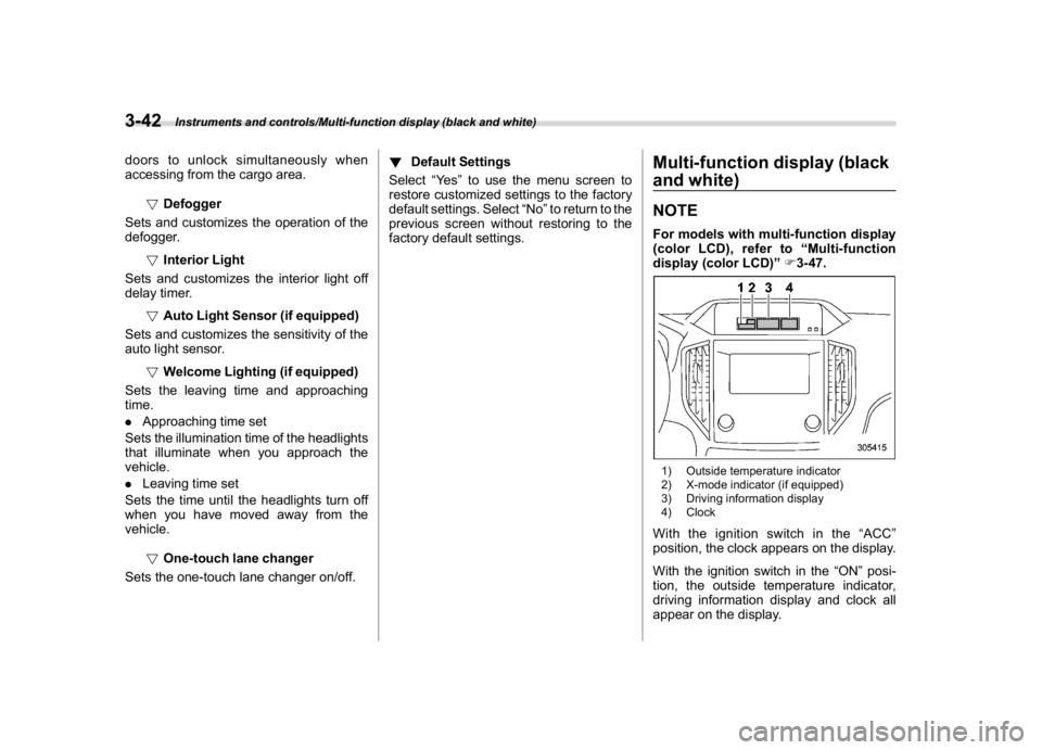
and white)NOTEFor models with multi-function display
(color LCD), refer to“Multi-function
display (color LCD)”F3-47.1) Outside temperature indicator
2) X-mode indicator (if equipped)
3) Driving information display
4) ClockWith the ignition switch in the“ACC”
position, the clock appears on the display.
With the ignition switch in the“ON”posi-
tion, the outside temperature indicator,
driving information display and clock all
appear on the display.
Instruments and controls/Multi-function display (black and white)
3-42
Page 179 of 474
(184,1)
北米Model "A1320BE-C" EDITED: 2017/ 10/ 10
time a complete hour has elapsed. If the
display is giving a reading other than the
journey time, the display switches to the
journey time, flashes for 5 seconds, and
returns to its original reading each time a
complete hour has elapsed.NOTEThe journey time is reset when the
ignition switch is turned to the“ACC”
or“LOCK”/“OFF”position.
!Average vehicle speed1) When units in miles is selected
2) When units in km is selectedThis display shows the average vehicle
speed since the trip meter was last reset.
Pressing the TRIP RESET switch toggles
the display between the average vehiclespeed corresponding to the A trip meter
display and the average vehicle speed
corresponding to the B trip meter display.
When either of the trip meter displays is
reset, the corresponding average vehicle
speed value is also reset.
NOTEWhen either trip meter display is reset,
the average vehicle speed correspond-
ing to that trip meter display is not
shown until the vehicle has subse-
quently covered a distance of 1 mile
(or 1 km).
!Turn off display of driving informa-
tion display
Select the blank space in the menu to exit
the driving information display selection.NOTE.The average fuel consumption and
average vehicle speed are calculated
even while the driving information dis-
play is not displayed.
.Even if you turn off the driving
information display, the display will
automatically turn on when the battery
voltage is disconnected and then re-
connected for battery replacement or
fuse replacement.
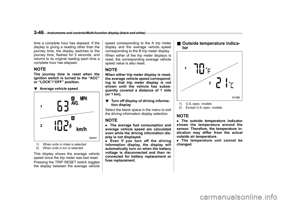
&Outside temperature indica-
tor1) U.S.-spec. models
2) Except U.S.-spec. modelsNOTE.The outside temperature indicator
shows the temperature around the
sensor. Therefore, the temperature in-
dication may differ from the actual
outside air temperature.
.The temperature unit cannot be
changed.
Instruments and controls/Multi-function display (black and white)
3-46
Page 183 of 474
(188,1)
北米Model "A1320BE-C" EDITED: 2017/ 10/ 10
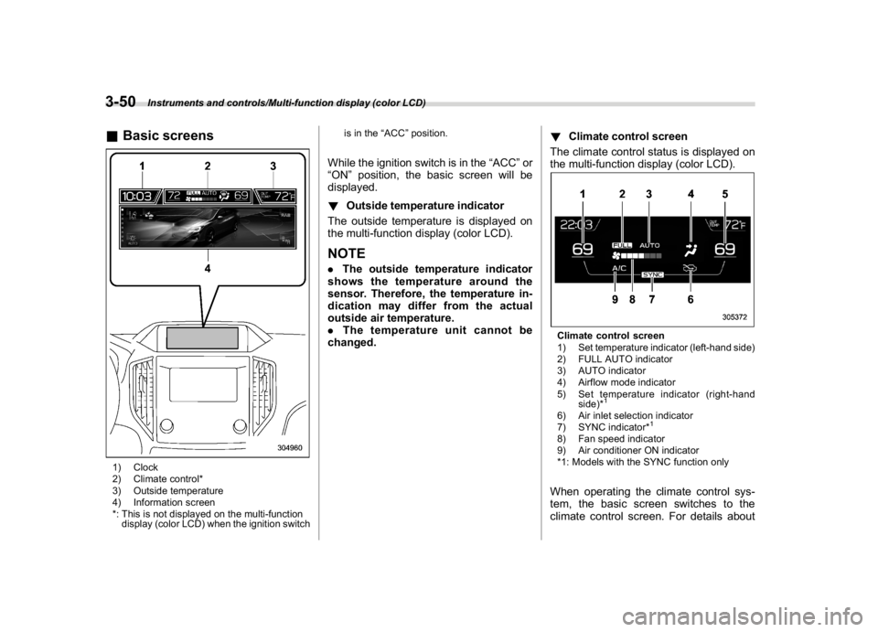
&Basic screens1) Clock
2) Climate control*
3) Outside temperature
4) Information screen
*: This is not displayed on the multi-function
display (color LCD) when the ignition switchis in the“ACC”position.
While the ignition switch is in the“ACC”or
“ON”position, the basic screen will be
displayed.
!Outside temperature indicator
The outside temperature is displayed on
the multi-function display (color LCD).NOTE.The outside temperature indicator
shows the temperature around the
sensor. Therefore, the temperature in-
dication may differ from the actual
outside air temperature.
.The temperature unit cannot be
changed.!Climate control screen
The climate control status is displayed on
the multi-function display (color LCD).
Climate control screen
1) Set temperature indicator (left-hand side)
2) FULL AUTO indicator
3) AUTO indicator
4) Airflow mode indicator
5) Set temperature indicator (right-hand
side)*
1
6) Air inlet selection indicator
7) SYNC indicator*
1
8) Fan speed indicator
9) Air conditioner ON indicator
*1: Models with the SYNC function onlyWhen operating the climate control sys-
tem, the basic screen switches to the
climate control screen. For details about
Instruments and controls/Multi-function display (color LCD)
3-50
Page 201 of 474
(206,1)
北米Model "A1320BE-C" EDITED: 2017/ 10/ 10
When exiting:
While the welcome lighting function is
activated, the low beam headlights will
remain illuminated even when either of the
following operation is done.
.The push-button ignition switch is
turned to the“OFF”status (models with
“keyless access with push-button start
system”)
.The key is pulled out from the ignition
switch (models without“keyless access
with push-button start system”)
The low beam headlights will turn off under
any of the following conditions.
.3 minutes have passed since the low
beam headlights were illuminated by the
welcome lighting function.
.30 seconds have passed since the door
is opened and closed.
*1
.The light control switch is turned to a
position other than“AUTO”.
.The locking procedure is performed
twice. When performing the unlocking
procedure after performing the locking
procedure, perform the locking procedure
twice again.*1: The setting for the period of time in which the
low beam headlights remain on by the welcome
lighting function can be changed by a SUBARU
dealer. Contact your SUBARU dealer for de-tails.
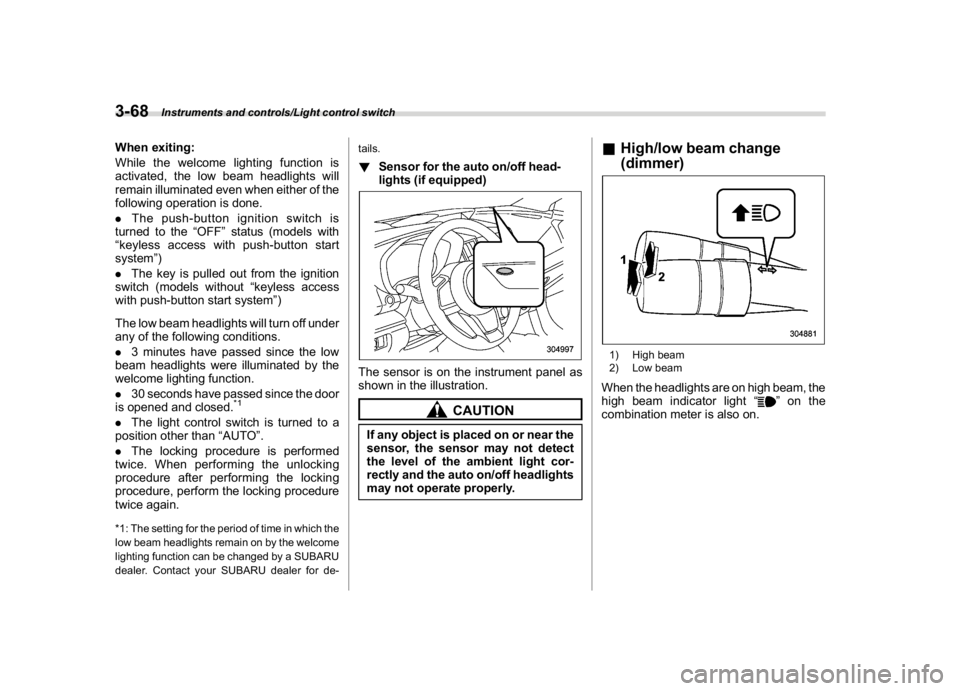
!Sensor for the auto on/off head-
lights (if equipped)The sensor is on the instrument panel as
shown in the illustration.
CAUTION
If any object is placed on or near the
sensor, the sensor may not detect
the level of the ambient light cor-
rectly and the auto on/off headlights
may not operate properly.
&High/low beam change
(dimmer)1) High beam
2) Low beamWhen the headlights are on high beam, the
high beam indicator light“
”on the
combination meter is also on.
Instruments and controls/Light control switch
3-68
Page 312 of 474
(321,1)
北米Model "A1320BE-C" EDITED: 2017/ 10/ 10
&System operation!Operating conditions
The BSD/RCTA will operate when all of the
following conditions are met.
.Theignitionswitchisinthe“ON”
position.
.The BSD/RCTA warning indicator and
BSD/RCTA OFF indicator are turned off.
.The vehicle is driven at speeds above 6
mph (10 km/h) (except when reversing).
.The shift lever/select lever is in the“R”
position (when reversing).
The BSD/RCTA will not operate in the
following situations.
.The BSD/RCTA OFF indicator is on.
.The vehicle speed is below 6 mph (10
km/h) even when the BSD/RCTA OFF
indicator remains off (except when rever-
sing).NOTE.In the following case, the BSD/RCTA
will stop operating and the BSD/RCTA
warning indicator will appear. If the
BSD/RCTA warning indicator appears,
have your vehicle inspected at a
SUBARU dealer as soon as possible.
–When a malfunction occurs in the
system, including the BSD/RCTA
approach indicator light.In the following cases, the BSD/
RCTA will temporarily stop operating
(or may stop operating) and the BSD/
RCTA warning indicator will appear.
–When the radar sensor becomes
significantly misaligned (If the or-
ientation of the radar sensor is
shifted for any reason, readjust-
ment is required. Have the sensor
adjusted at a SUBARU dealer.)
–When a large amount of snow or
ice sticks to the rear bumper sur-
face around the radar sensors
–When the vehicle is driven on a
snow-covered road or in an envir-
onment in which there are no ob-
jects around (such as in a desert) for
a long time
–When the temperature around the
radar sensors increased exces-
sively due to long driving on uphill
grades in summer, etc.
–When the temperature around the
radar sensors becomes extremely
low
–When the vehicle battery voltage
lowers
–When the vehicle battery be-
comes overvoltage
When the above conditions are cor-
rected, the BSD/RCTA will resume op-eration and the BSD/RCTA warning
indicator will disappear. However, if
the BSD/RCTA warning indicator has
appeared for a prolonged time, have the
system inspected at a SUBARU dealer
as soon as possible.
.The detectability of the radar sen-
sors is restricted. The BSD/RCTA de-
tection may be impaired and the system
may not operate properly under the
following conditions.
–When the rear bumper around the
radar sensors is distorted
–When ice, snow or mud adheres
to the rear bumper surface around
the radar sensors
–When stickers, etc. are affixed on
the areas of the radar sensors on
the rear bumper
–During adverse weather condi-
tions such as rain, snow or fog
–When driving on wet roads such
as snow-covered roads and through
puddles
.The radar sensors may not detect or
may have difficulty detecting the fol-
lowing.
–Small motorcycles, bicycles, pe-
destrians, stationary objects on the
road or road side, etc.
–Vehicles with body shapes that
the radar may not reflect (vehicles
–CONTINUED–
Starting and operating/BSD/RCTA
7-55
7
Page 313 of 474
(322,1)
北米Model "A1320BE-C" EDITED: 2017/ 10/ 10
with a low body height such as
sports cars or a trailer with no
cargo)
–Vehicles that are not approaching
your vehicle even though they are in
the detection area (either on a
neighboring lane to the rear or be-
side your vehicle when reversing)
(The system determines the pre-
sence of approaching vehicles
based on data detected by the radar
sensors.)
–Vehicles traveling at significantly
different speeds
–Vehicles driving in parallel at al-
most the same speed as your vehi-
cle for a prolonged time
–Oncoming vehicles
–Vehicles in a lane beyond the
neighboring lane
–Vehicles travelling at a signifi-
cantly lower speed that you are
trying to overtake
.On a road with extremely narrow
lanes, the system may detect vehicles
driving in a lane next to the neighboring
lane.
.When the 8-inch audio/navigation
system is performing a software up-
date, the RCTA warning icons may not
be displayed on the audio/navigation
screen until the update is complete.
&BSD/RCTA approach indica-
tor light/warning buzzerWhen the BSD/RCTA is active, the BSD/
RCTA approach indicator light will operate
to alert the driver when there are vehicles
in the neighboring lanes. When reversing
the vehicle, the BSD/RCTA approach
indicator light and warning buzzer will
operate to alert the driver that a vehicle is
approaching from the left or right side.
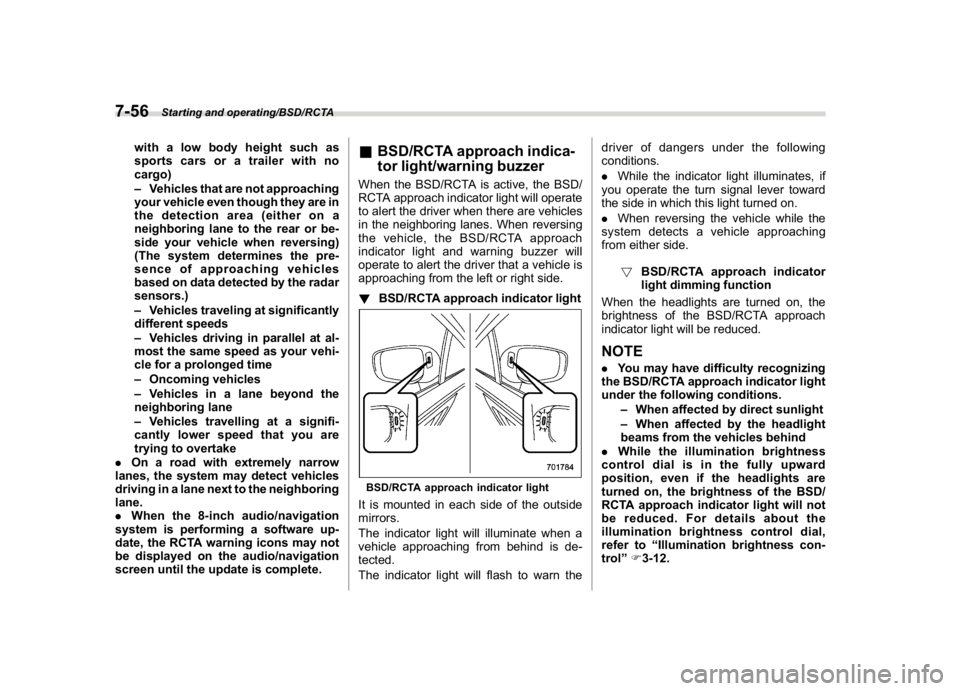
!BSD/RCTA approach indicator lightBSD/RCTA approach indicator lightIt is mounted in each side of the outside
mirrors.
The indicator light will illuminate when a
vehicle approaching from behind is de-
tected.
The indicator light will flash to warn thedriver of dangers under the following
conditions.
.While the indicator light illuminates, if
you operate the turn signal lever toward
the side in which this light turned on.
.When reversing the vehicle while the
system detects a vehicle approaching
from either side.
!BSD/RCTA approach indicator
light dimming function
When the headlights are turned on, the
brightness of the BSD/RCTA approach
indicator light will be reduced.
NOTE.You may have difficulty recognizing
the BSD/RCTA approach indicator light
under the following conditions.
–When affected by direct sunlight
–When affected by the headlight
beams from the vehicles behind
.While the illumination brightness
control dial is in the fully upward
position, even if the headlights are
turned on, the brightness of the BSD/
RCTA approach indicator light will not
be reduced. For details about the
illumination brightness control dial,
refer to“Illumination brightness con-
trol”F3-12.
Starting and operating/BSD/RCTA
7-56
Page 318 of 474
(327,1)
北米Model "A1320BE-C" EDITED: 2017/ 10/ 10
sensor becomes misaligned, a system
malfunction may occur, including the in-
ability to detect vehicles entering the
detection areas. If any strong shock is
applied to the bumper, be sure to contact
your SUBARU dealer for inspection.
.Do not disassemble the radar sensors.NOTEIf the radar sensors require repair or
replacement, or the bumper area
around the radar sensors requires
repair, paintwork or replacement, con-
tact your SUBARU dealer for assis-
tance.
Reverse Automatic Braking
System (if equipped)Reverse Automatic Braking is a system
designed to help avoid collisions or reduce
collision damage when reversing the
vehicle. If a wall or an obstacle is detected
in the reversing direction, the system will
notify the driver with a warning sound and
may activate the vehicle’s brakes auto-
matically.
WARNING
.Reverse Automatic Braking is not
a system intended to replace the
driver’s responsibility to check
surrounding areas for vehicles or
obstacles to avoid a collision.
.The driver is responsible for driv-
ing safely. Always be sure to
check the surroundings visually
when reversing the vehicle.
.Since the system operation has
various limitations, the warning
sound or automatic braking may
be delayed or may not operate at
all even when an obstacle is
present in the reversing direc-
tion.
.The system is not designed todetect people (including chil-
dren), animals or other moving
objects.
.Depending on the vehicle condi-
tion or the surrounding environ-
ment, the sonar sensor’s ability
to detect objects may be compro-
mised.
NOTEThe Reverse Automatic Braking Sys-
tem records and stores the following
data when automatic braking operates.
It does not record conversations, per-
sonal information or other audio data.
.Distance from the object
.Vehicle speed
.Accelerator pedal operation status
.Brake pedal operation status
.Select lever position
.Outside temperature
.The sensitivity setting of the sonar
sensors
SUBARU and third parties contracted
by SUBARU may acquire and use the
recorded data for the purpose of vehi-
cle research and development.
SUBARU and third parties contracted
by SUBARU will not disclose or provide
the acquired data to any other third
–CONTINUED–
Starting and operating/Reverse Automatic Braking System
7-61
7
Page 319 of 474
(328,1)
北米Model "A1320BE-C" EDITED: 2017/ 10/ 10
party except under the following con-
ditions.
.The vehicle owner has given his/her
consent.
.The disclosure/provision is based
on a court order or other legally en-
forceable request.
.Data that has been modified so that
the user and vehicle cannot be identi-
fied is provided to a research institution
for statistical processing or similar
purposes.&Reverse Automatic Braking
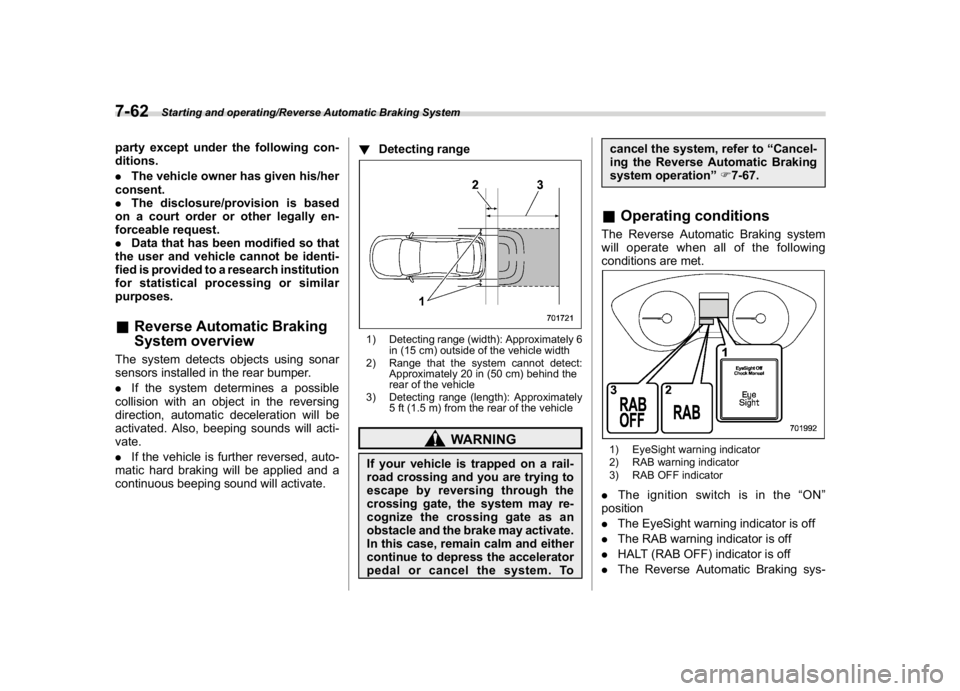
System overviewThe system detects objects using sonar
sensors installed in the rear bumper.
.If the system determines a possible
collision with an object in the reversing
direction, automatic deceleration will be
activated. Also, beeping sounds will acti-
vate.
.If the vehicle is further reversed, auto-
matic hard braking will be applied and a
continuous beeping sound will activate.!Detecting range
1) Detecting range (width): Approximately 6
in (15 cm) outside of the vehicle width
2) Range that the system cannot detect:
Approximately 20 in (50 cm) behind the
rear of the vehicle
3) Detecting range (length): Approximately
5 ft (1.5 m) from the rear of the vehicle
WARNING
If your vehicle is trapped on a rail-
road crossing and you are trying to
escape by reversing through the
crossing gate, the system may re-
cognize the crossing gate as an
obstacle and the brake may activate.
In this case, remain calm and either
continue to depress the accelerator
pedal or cancel the system. Tocancel the system, refer to“Cancel-
ing the Reverse Automatic Braking
system operation”F7-67.
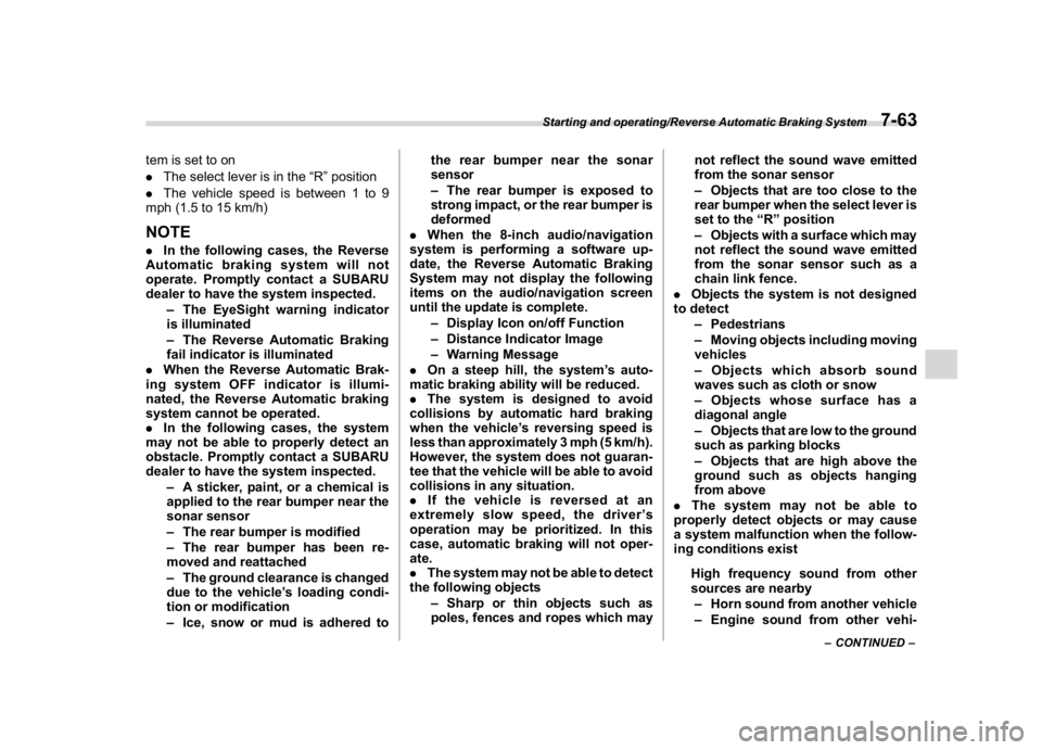
&Operating conditionsThe Reverse Automatic Braking system
will operate when all of the following
conditions are met.1) EyeSight warning indicator
2) RAB warning indicator
3) RAB OFF indicator.Theignitionswitchisinthe“ON”
position
.The EyeSight warning indicator is off
.The RAB warning indicator is off
.HALT (RAB OFF) indicator is off
.The Reverse Automatic Braking sys-
Starting and operating/Reverse Automatic Braking System
7-62
Page 320 of 474
(329,1)
北米Model "A1320BE-C" EDITED: 2017/ 10/ 10
tem is set to on
.The select lever is in the“R”position
.The vehicle speed is between 1 to 9
mph (1.5 to 15 km/h)NOTE.In the following cases, the Reverse
Automatic braking system will not
operate. Promptly contact a SUBARU
dealer to have the system inspected.
–The EyeSight warning indicator
is illuminated
–The Reverse Automatic Braking
fail indicator is illuminated
.When the Reverse Automatic Brak-
ing system OFF indicator is illumi-
nated, the Reverse Automatic braking
system cannot be operated.
.In the following cases, the system
may not be able to properly detect an
obstacle. Promptly contact a SUBARU
dealer to have the system inspected.
–A sticker, paint, or a chemical is
applied to the rear bumper near the
sonar sensor
–The rear bumper is modified
–The rear bumper has been re-
moved and reattached
–The ground clearance is changed
due to the vehicle’s loading condi-
tion or modification
–Ice, snow or mud is adhered tothe rear bumper near the sonar
sensor
–The rear bumper is exposed to
strong impact, or the rear bumper is
deformed
.When the 8-inch audio/navigation
system is performing a software up-
date, the Reverse Automatic Braking
System may not display the following
items on the audio/navigation screen
until the update is complete.
–Display Icon on/off Function
–Distance Indicator Image
–Warning Message
.On a steep hill, the system’s auto-
matic braking ability will be reduced.
.The system is designed to avoid
collisions by automatic hard braking
when the vehicle’s reversing speed is
less than approximately 3 mph (5 km/h).
However, the system does not guaran-
tee that the vehicle will be able to avoid
collisions in any situation.
.If the vehicle is reversed at an
extremely slow speed, the driver’s
operation may be prioritized. In this
case, automatic braking will not oper-
ate.
.The system may not be able to detect
the following objects
–Sharp or thin objects such as
poles, fences and ropes which maynot reflect the sound wave emitted
from the sonar sensor
–Objects that are too close to the
rear bumper when the select lever is
set to the“R”position
–Objects with a surface which may
not reflect the sound wave emitted
from the sonar sensor such as a
chain link fence.
.Objects the system is not designed
to detect
–Pedestrians
–Moving objects including moving
vehicles
–Objects which absorb sound
waves such as cloth or snow
–Objects whose surface has a
diagonal angle
–Objects that are low to the ground
such as parking blocks
–Objects that are high above the
ground such as objects hanging
from above
.The system may not be able to
properly detect objects or may cause
a system malfunction when the follow-
ing conditions exist
High frequency sound from other
sources are nearby
–Horn sound from another vehicle
–Engine sound from other vehi-
–CONTINUED–
Starting and operating/Reverse Automatic Braking System
7-63
7