wiring SUBARU FORESTER 1999 Service Repair Manual
[x] Cancel search | Manufacturer: SUBARU, Model Year: 1999, Model line: FORESTER, Model: SUBARU FORESTER 1999Pages: 345, PDF Size: 5.6 MB
Page 60 of 345
3) Conduct appearance inspection on parts
selected.
NOTE:
Also check connector terminals, wiring harness,
case, etc. for damage.
:Is there anything unusual about the
appearance of airbag component
parts?
: Replace faulty airbag component parts.
: Go to step5X2.
5X2 : AIRBAG COMPONENT PARTS
VIBRATION INSPECTION
1) Gently shake check parts (to determine faults.).
2) To check airbag module or roll connector, turn
and tilt steering wheel.
CAUTION:
Do not shake or vibrate airbag control module.
:Does the component malfunction
again when shaking?
: Replace faulty airbag component parts.
: Go to step5X3.
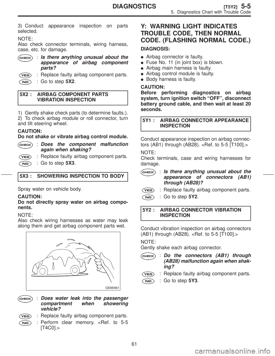
5X3 : SHOWERING INSPECTION TO BODY
Spray water on vehicle body.
CAUTION:
Do not directly spray water on airbag compo-
nents.
NOTE:
Also check wiring harnesses as water may leak
along them and get airbag component parts wet.
G5M0461
:Does water leak into the passenger
compartment when showering
vehicle?
: Replace faulty airbag component parts.
: Perform clear memory.
Y: WARNING LIGHT INDICATES
TROUBLE CODE, THEN NORMAL
CODE. (FLASHING NORMAL CODE.)
DIAGNOSIS:
IAirbag connector is faulty.
IFuse No. 11 (in joint box) is blown.
IAirbag main harness is faulty.
IAirbag control module is faulty.
IBody harness is faulty.
CAUTION:
Before performing diagnostics on airbag
system, turn ignition switch ªOFFº, disconnect
battery ground cable, and then wait at least 20
seconds.
5Y1 : AIRBAG CONNECTOR APPEARANCE
INSPECTION
Conduct appearance inspection on airbag connec-
tors (AB1) through (AB28).
NOTE:
Check terminals, case and wiring harnesses for
damage.
:Is there anything unusual about the
appearance of connectors (AB1)
through (AB28)?
: Replace faulty airbag component parts.
: Go to step5Y2.
5Y2 : AIRBAG CONNECTOR VIBRATION
INSPECTION
Conduct vibration inspection on airbag connectors
(AB1) through (AB28).
NOTE:
Gently shake each airbag connector.
:Do the connectors (AB1) through
(AB28) malfunction again when shak-
ing?
: Replace faulty airbag component parts.
: Go to step5Y3.
61
[T5Y2]5-5DIAGNOSTICS
5. Diagnostics Chart with Trouble Code
Page 61 of 345
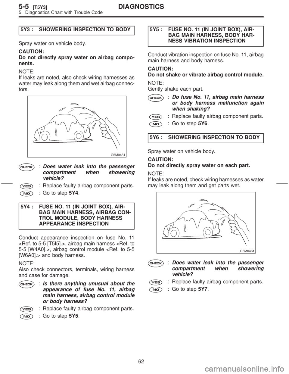
5Y3 : SHOWERING INSPECTION TO BODY
Spray water on vehicle body.
CAUTION:
Do not directly spray water on airbag compo-
nents.
NOTE:
If leaks are noted, also check wiring harnesses as
water may leak along them and wet airbag connec-
tors.
G5M0461
:Does water leak into the passenger
compartment when showering
vehicle?
: Replace faulty airbag component parts.
: Go to step5Y4.
5Y4 : FUSE NO. 11 (IN JOINT BOX), AIR-
BAG MAIN HARNESS, AIRBAG CON-
TROL MODULE, BODY HARNESS
APPEARANCE INSPECTION
Conduct appearance inspection on fuse No. 11
NOTE:
Also check connectors, terminals, wiring harness
and case for damage.
:Is there anything unusual about the
appearance of fuse No. 11, airbag
main harness, airbag control module
or body harness?
: Replace faulty airbag component parts.
: Go to step5Y5.5Y5 : FUSE NO. 11 (IN JOINT BOX), AIR-
BAG MAIN HARNESS, BODY HAR-
NESS VIBRATION INSPECTION
Conduct vibration inspection on fuse No. 11, airbag
main harness and body harness.
CAUTION:
Do not shake or vibrate airbag control module.
NOTE:
Gently shake each part.
:Do fuse No. 11, airbag main harness
or body harness malfunction again
when shaking?
: Replace faulty airbag component parts.
: Go to step5Y6.
5Y6 : SHOWERING INSPECTION TO BODY
Spray water on vehicle body.
CAUTION:
Do not directly spray water on each part.
NOTE:
If leaks are noted, check wiring harnesses as water
may leak along them and get parts wet.
G5M0461
:Does water leak into the passenger
compartment when showering
vehicle?
: Replace faulty airbag component parts.
: Go to step5Y7.
62
5-5[T5Y3]DIAGNOSTICS
5. Diagnostics Chart with Trouble Code
Page 65 of 345
1A4 : CHECK TRANSMISSION TYPE.
:Is the transmission type MT?
: Go to step1A5.
: Go to step1A9.
1A5 : CHECK HARNESS CONNECTOR
BETWEEN COMBINATION METER
AND VEHICLE SPEED SENSOR.
1) Disconnect connector from vehicle speed sen-
sor.
2) Measure resistance of harness connector
between vehicle speed sensor and combination
meter.
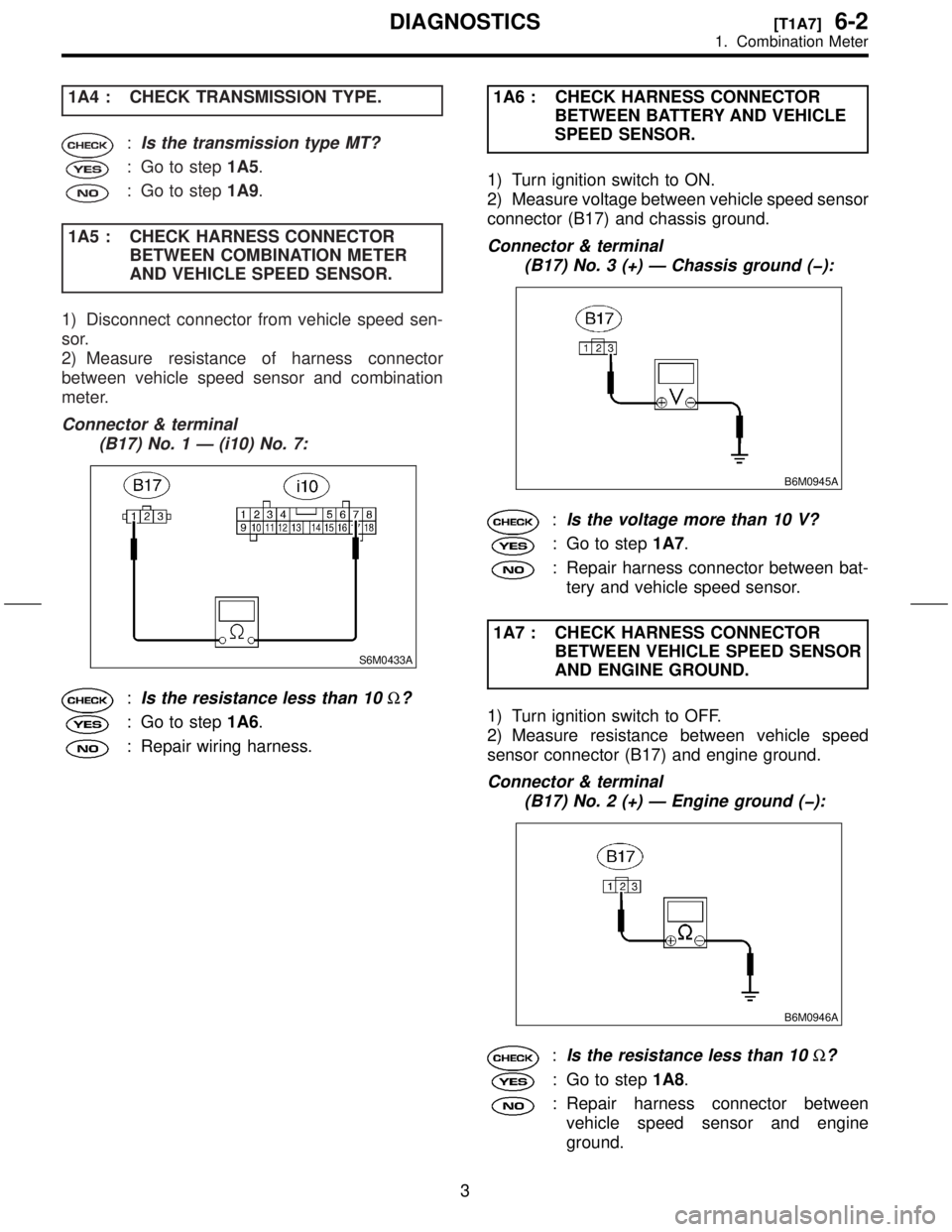
Connector & terminal
(B17) No. 1 Ð (i10) No. 7:
S6M0433A
:Is the resistance less than 10W?
: Go to step1A6.
: Repair wiring harness.1A6 : CHECK HARNESS CONNECTOR
BETWEEN BATTERY AND VEHICLE
SPEED SENSOR.
1) Turn ignition switch to ON.
2) Measure voltage between vehicle speed sensor
connector (B17) and chassis ground.
Connector & terminal
(B17) No. 3 (+) Ð Chassis ground (þ):
B6M0945A
:Is the voltage more than 10 V?
: Go to step1A7.
: Repair harness connector between bat-
tery and vehicle speed sensor.
1A7 : CHECK HARNESS CONNECTOR
BETWEEN VEHICLE SPEED SENSOR
AND ENGINE GROUND.
1) Turn ignition switch to OFF.
2) Measure resistance between vehicle speed
sensor connector (B17) and engine ground.
Connector & terminal
(B17) No. 2 (+) Ð Engine ground (þ):
B6M0946A
:Is the resistance less than 10W?
: Go to step1A8.
: Repair harness connector between
vehicle speed sensor and engine
ground.
3
[T1A7]6-2DIAGNOSTICS
1. Combination Meter
Page 69 of 345
![SUBARU FORESTER 1999 Service Repair Manual 2. AT Shift Lock System
A: WIRING DIAGRAM
SU42-04
7
[T2A0]6-2DIAGNOSTICS
2. AT Shift Lock System SUBARU FORESTER 1999 Service Repair Manual 2. AT Shift Lock System
A: WIRING DIAGRAM
SU42-04
7
[T2A0]6-2DIAGNOSTICS
2. AT Shift Lock System](/img/17/57427/w960_57427-68.png)
2. AT Shift Lock System
A: WIRING DIAGRAM
SU42-04
7
[T2A0]6-2DIAGNOSTICS
2. AT Shift Lock System
Page 75 of 345
3. Cruise Control System
A: PRECAUTION
1. SUPPLEMENTAL RESTRAINT SYSTEM
ªAIRBAGº
Airbag system wiring harness is routed near the
cruise control module and cruise control command
switch.
CAUTION:
IAll airbag system wiring harness and con-
nectors are yellow. Do not use electrical test
equipment on these circuits.
IBe careful not to damage airbag system wir-
ing harness when servicing the cruise control
module and cruise control command switch.
B: PRE-INSPECTION
1. FUNCTION TESTS
Conduct road tests by selecting a smooth, flat road
or use free rollers for road test simulation.
ICruise Control Main Switch
1) Turn ignition switch to ON.
2) Check that cruise control main switch indicator
light comes on when main switch is pressed (ON).
3) Check that main switch indicator light goes out
when main switch is pressed again (OFF).
4) Turn ignition switch to OFF with main switch ON
(indicated by illumination). Turn ignition switch ON
again to ensure that main switch indicator light
remains OFF.
ICruise Control Command Switch
1) Check that cruise control command switch is
properly set in ªSET/COASTº, ªRESUME/ACCELº,
or ªCANCELº mode.
2) Also check that command switch returns to the
original position when released.
IConstant Speed Test
1) Turn cruise control main switch to ON.
2) Drive the vehicle at a speed greater than 40
km/h (25 MPH).
3) Press command switch to set in ªSET/COASTº
mode.
4) Ensure that vehicle is maintained at the speed
set when command switch was pressed.
IAcceleration Test
1) Set vehicle speed at a speed greater that 40
km/h (25 MPH).
2) Ensure that vehicle continues to accelerate
while holding command switch in ªRESUME/
ACCELº mode, and that vehicle maintains that
optional speed when command switch is released.
IDeceleration Test
1) Set vehicle speed at an optional speed greater
than 40 km/h (25 MPH).
2) Ensure that vehicle continues to decelerate
while holding command switch in ªSET/COASTº
mode, and that it maintains that optional speed
when command switch is released.
NOTE:
When vehicle speed reaches the lower speed limit
of 30 km/h (19 MPH) during deceleration, cruise
control will be released.
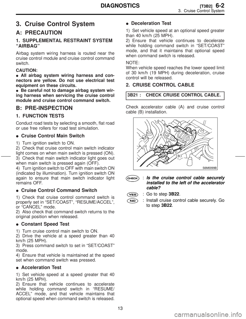
2. CRUISE CONTROL CABLE
3B21 : CHECK CRUISE CONTROL CABLE.
Check accelerator cable (A) and cruise control
cable (B) installation.
S6M0099B
:Is the cruise control cable securely
installed to the left of the accelerator
cable?
: Go to step3B22.
: Install cruise control cable securely. Go
to step3B22.
13
[T3B2]6-2DIAGNOSTICS
3. Cruise Control System
Page 86 of 345
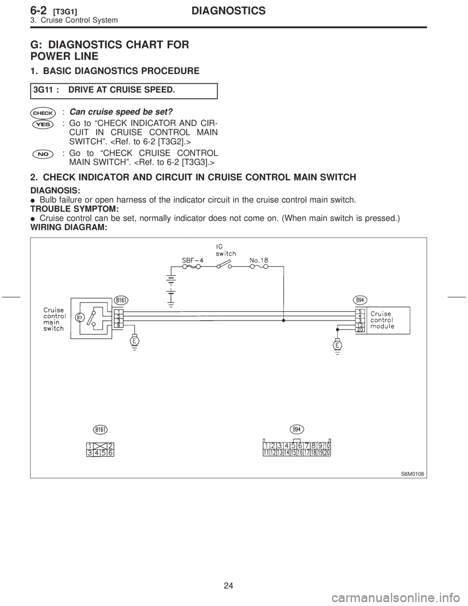
G: DIAGNOSTICS CHART FOR
POWER LINE
1. BASIC DIAGNOSTICS PROCEDURE
3G11 : DRIVE AT CRUISE SPEED.
:Can cruise speed be set?
: Go to ªCHECK INDICATOR AND CIR-
CUIT IN CRUISE CONTROL MAIN
SWITCHº.
: Go to ªCHECK CRUISE CONTROL
MAIN SWITCHº.
2. CHECK INDICATOR AND CIRCUIT IN CRUISE CONTROL MAIN SWITCH
DIAGNOSIS:
IBulb failure or open harness of the indicator circuit in the cruise control main switch.
TROUBLE SYMPTOM:
ICruise control can be set, normally indicator does not come on. (When main switch is pressed.)
WIRING DIAGRAM:
S6M0108
24
6-2[T3G1]DIAGNOSTICS
3. Cruise Control System
Page 87 of 345
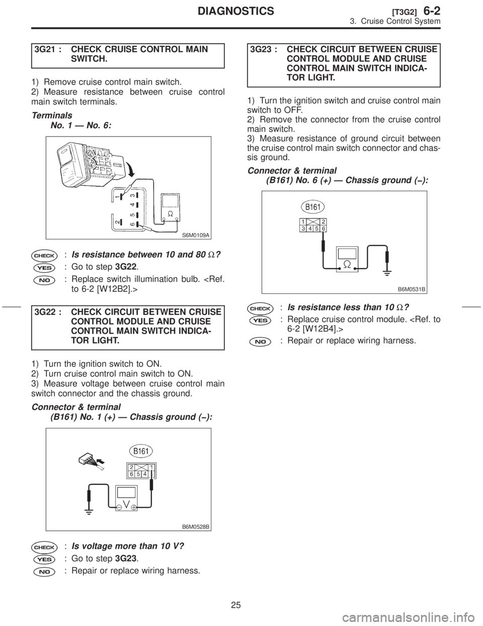
3G21 : CHECK CRUISE CONTROL MAIN
SWITCH.
1) Remove cruise control main switch.
2) Measure resistance between cruise control
main switch terminals.
Terminals
No. 1 Ð No. 6:
S6M0109A
:Is resistance between 10 and 80W?
: Go to step3G22.
: Replace switch illumination bulb.
3G22 : CHECK CIRCUIT BETWEEN CRUISE
CONTROL MODULE AND CRUISE
CONTROL MAIN SWITCH INDICA-
TOR LIGHT.
1) Turn the ignition switch to ON.
2) Turn cruise control main switch to ON.
3) Measure voltage between cruise control main
switch connector and the chassis ground.
Connector & terminal
(B161) No. 1 (+) Ð Chassis ground (þ):
B6M0528B
:Is voltage more than 10 V?
: Go to step3G23.
: Repair or replace wiring harness.3G23 : CHECK CIRCUIT BETWEEN CRUISE
CONTROL MODULE AND CRUISE
CONTROL MAIN SWITCH INDICA-
TOR LIGHT.
1) Turn the ignition switch and cruise control main
switch to OFF.
2) Remove the connector from the cruise control
main switch.
3) Measure resistance of ground circuit between
the cruise control main switch connector and chas-
sis ground.
Connector & terminal
(B161) No. 6 (+) Ð Chassis ground (þ):
B6M0531B
:Is resistance less than 10W?
: Replace cruise control module.
: Repair or replace wiring harness.
25
[T3G2]6-2DIAGNOSTICS
3. Cruise Control System
Page 88 of 345
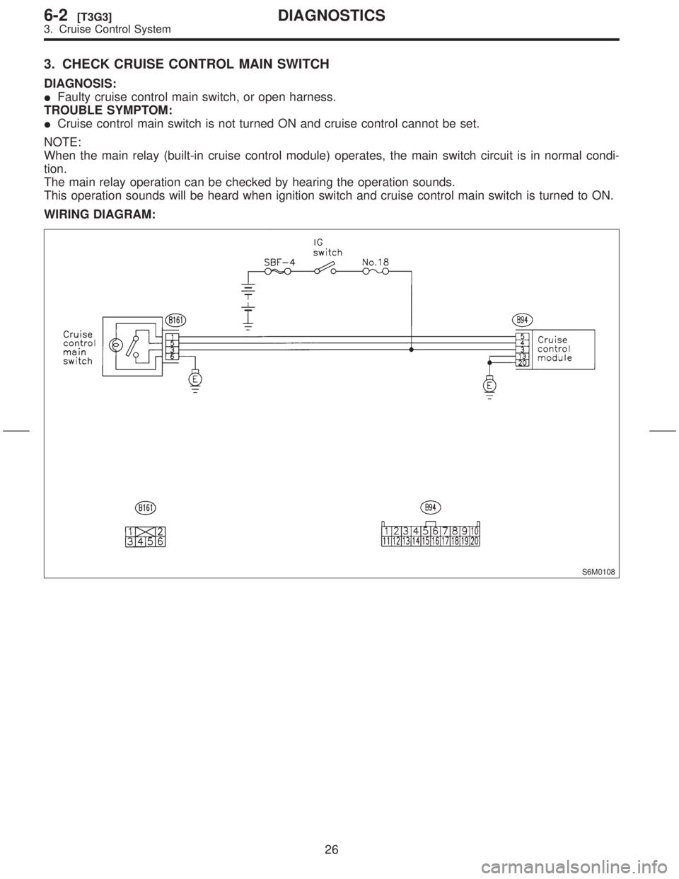
3. CHECK CRUISE CONTROL MAIN SWITCH
DIAGNOSIS:
IFaulty cruise control main switch, or open harness.
TROUBLE SYMPTOM:
ICruise control main switch is not turned ON and cruise control cannot be set.
NOTE:
When the main relay (built-in cruise control module) operates, the main switch circuit is in normal condi-
tion.
The main relay operation can be checked by hearing the operation sounds.
This operation sounds will be heard when ignition switch and cruise control main switch is turned to ON.
WIRING DIAGRAM:
S6M0108
26
6-2[T3G3]DIAGNOSTICS
3. Cruise Control System
Page 90 of 345
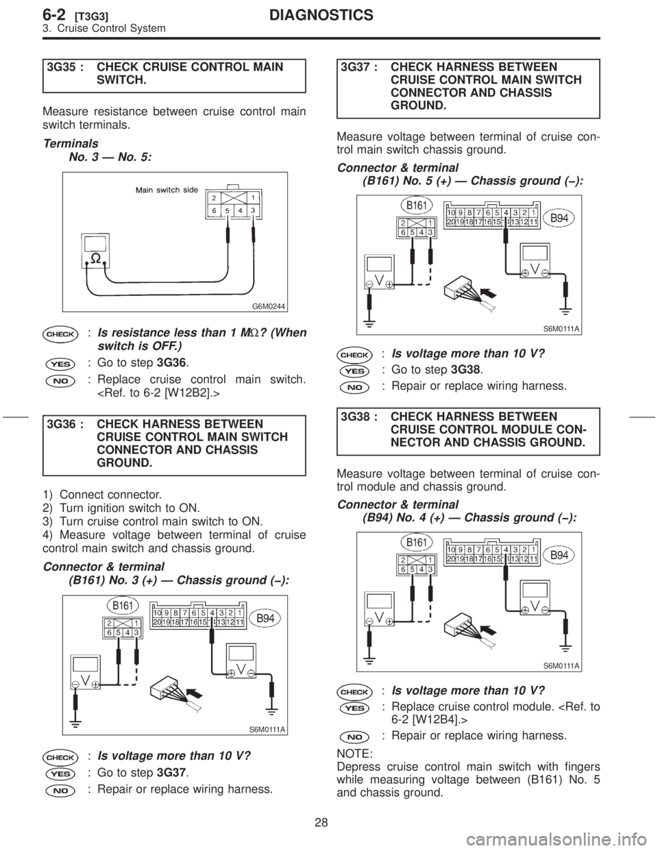
3G35 : CHECK CRUISE CONTROL MAIN
SWITCH.
Measure resistance between cruise control main
switch terminals.
Terminals
No. 3 Ð No. 5:
G6M0244
:Is resistance less than 1 MW? (When
switch is OFF.)
: Go to step3G36.
: Replace cruise control main switch.
3G36 : CHECK HARNESS BETWEEN
CRUISE CONTROL MAIN SWITCH
CONNECTOR AND CHASSIS
GROUND.
1) Connect connector.
2) Turn ignition switch to ON.
3) Turn cruise control main switch to ON.
4) Measure voltage between terminal of cruise
control main switch and chassis ground.
Connector & terminal
(B161) No. 3 (+) Ð Chassis ground (þ):
S6M0111A
:Is voltage more than 10 V?
: Go to step3G37.
: Repair or replace wiring harness.3G37 : CHECK HARNESS BETWEEN
CRUISE CONTROL MAIN SWITCH
CONNECTOR AND CHASSIS
GROUND.
Measure voltage between terminal of cruise con-
trol main switch chassis ground.
Connector & terminal
(B161) No. 5 (+) Ð Chassis ground (þ):
S6M0111A
:Is voltage more than 10 V?
: Go to step3G38.
: Repair or replace wiring harness.
3G38 : CHECK HARNESS BETWEEN
CRUISE CONTROL MODULE CON-
NECTOR AND CHASSIS GROUND.
Measure voltage between terminal of cruise con-
trol module and chassis ground.
Connector & terminal
(B94) No. 4 (+) Ð Chassis ground (þ):
S6M0111A
:Is voltage more than 10 V?
: Replace cruise control module.
: Repair or replace wiring harness.
NOTE:
Depress cruise control main switch with fingers
while measuring voltage between (B161) No. 5
and chassis ground.
28
6-2[T3G3]DIAGNOSTICS
3. Cruise Control System
Page 92 of 345
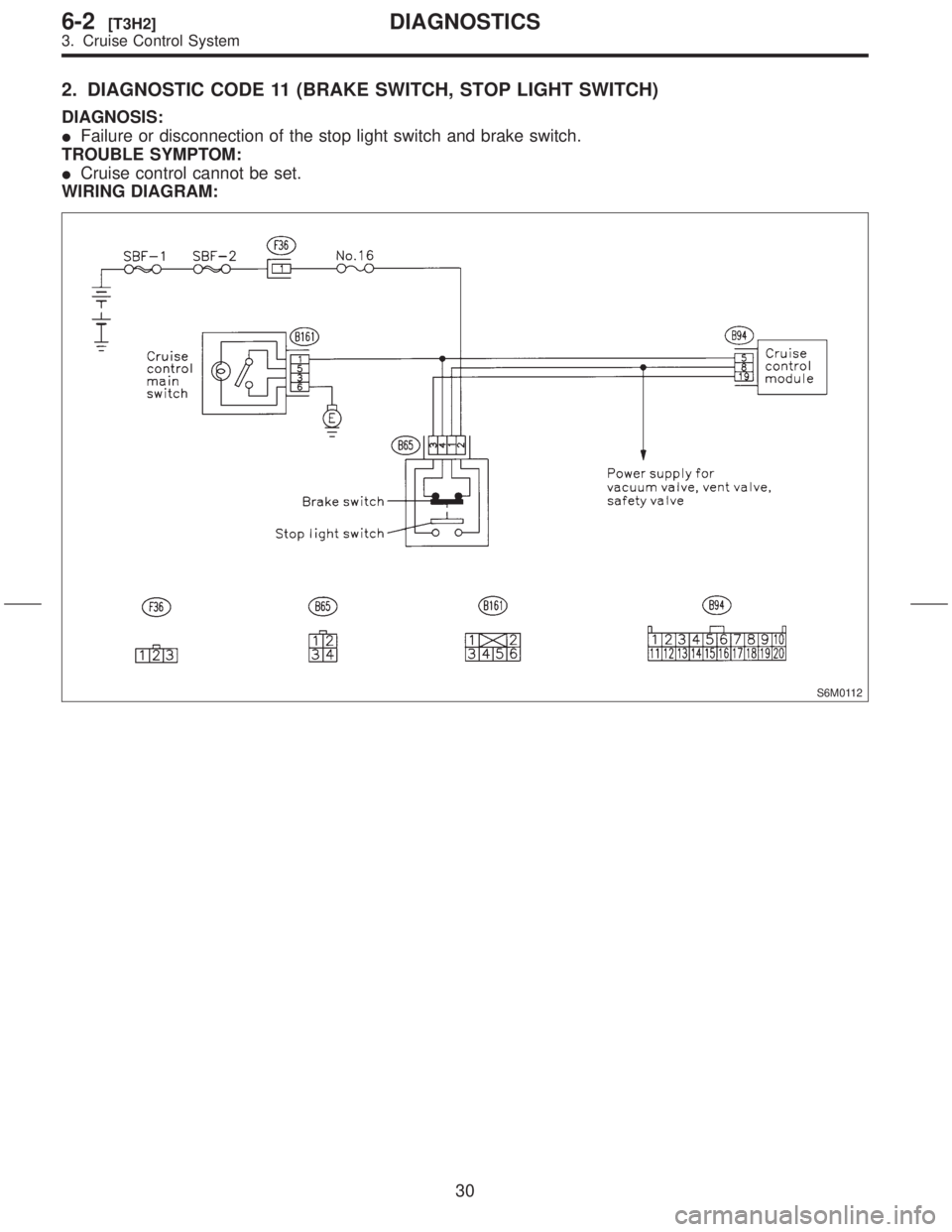
2. DIAGNOSTIC CODE 11 (BRAKE SWITCH, STOP LIGHT SWITCH)
DIAGNOSIS:
IFailure or disconnection of the stop light switch and brake switch.
TROUBLE SYMPTOM:
ICruise control cannot be set.
WIRING DIAGRAM:
S6M0112
30
6-2[T3H2]DIAGNOSTICS
3. Cruise Control System