engine oil SUBARU FORESTER 2004 Service Owners Manual
[x] Cancel search | Manufacturer: SUBARU, Model Year: 2004, Model line: FORESTER, Model: SUBARU FORESTER 2004Pages: 2870, PDF Size: 38.67 MB
Page 1373 of 2870
FU(H4DOTC)-18
FUEL INJECTION (FUEL SYSTEM)
Intake Manifold
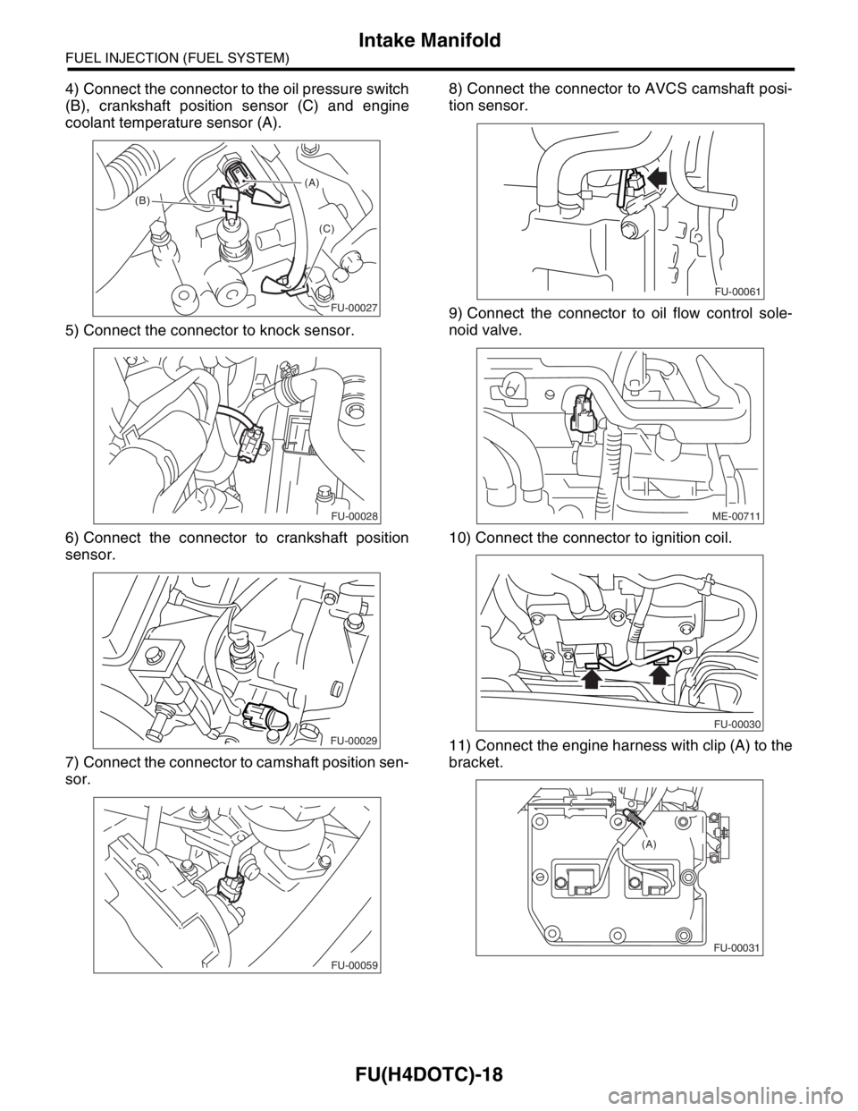
4) Connect the connector to the oil pressure switch
(B), crankshaft position sensor (C) and engine
coolant temperature sensor (A).
5) Connect the connector to knock sensor.
6) Connect the connector to crankshaft position
sensor.
7) Connect the connector to camshaft position sen-
sor.8) Connect the connector to AVCS camshaft posi-
tion sensor.
9) Connect the connector to oil flow control sole-
noid valve.
10) Connect the connector to ignition coil.
11) Connect the engine harness with clip (A) to the
bracket.
(A)
(B)
(C)
FU-00027
FU-00028
FU-00029
FU-00059
FU-00061
ME-00711
FU-00030
FU-00031
(A)
Page 1444 of 2870
IN(H4DOTC)-5
INTAKE (INDUCTION)
General Description
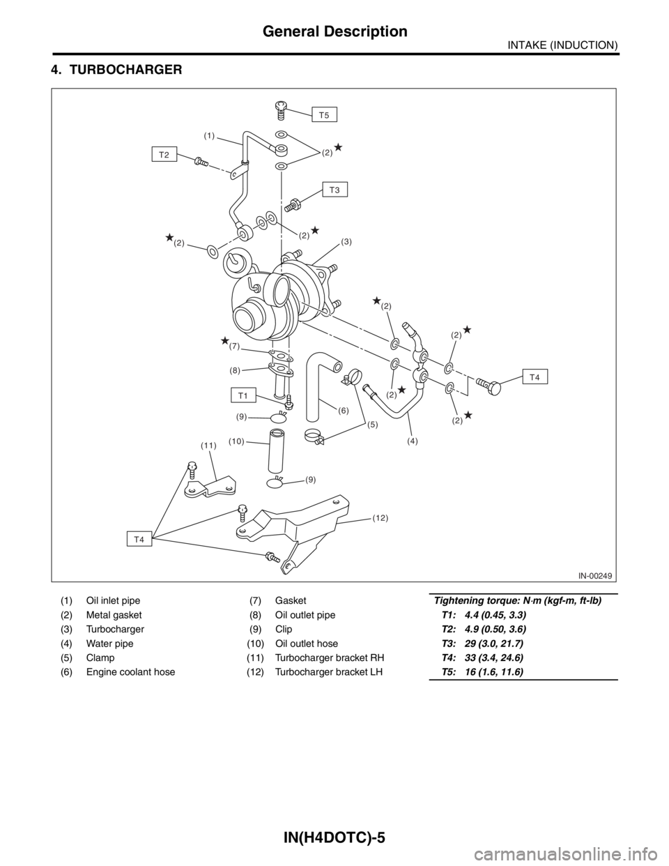
4. TURBOCHARGER
(1) Oil inlet pipe (7) GasketTightening torque: N⋅m (kgf-m, ft-lb)
(2) Metal gasket (8) Oil outlet pipeT1: 4.4 (0.45, 3.3)
(3) Turbocharger (9) ClipT2: 4.9 (0.50, 3.6)
(4) Water pipe (10) Oil outlet hoseT3: 29 (3.0, 21.7)
(5) Clamp (11) Turbocharger bracket RHT4: 33 (3.4, 24.6)
(6) Engine coolant hose (12) Turbocharger bracket LHT5: 16 (1.6, 11.6)
IN-00249
T5
T1(3)
(8)
(4) (5) (9)
(9)(6)
(12) (1)
(2)
(2)
(2)
(2)
(2)
(7)
(2)
(11)(10)
T4
T2
T3
T4
(2)
Page 1451 of 2870
IN(H4DOTC)-12
INTAKE (INDUCTION)
Turbocharger
6. Turbocharger
A: REMOVAL
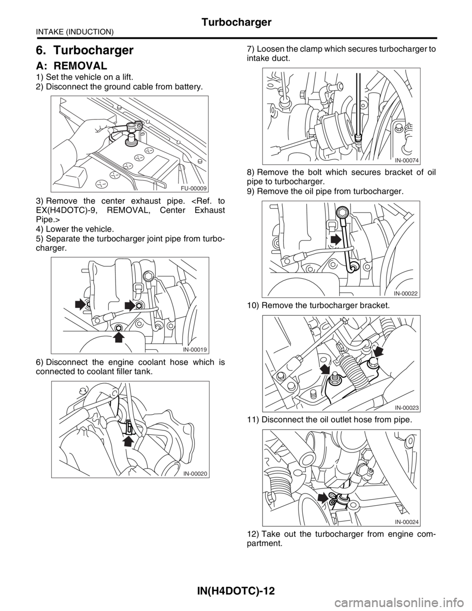
1) Set the vehicle on a lift.
2) Disconnect the ground cable from battery.
3) Remove the center exhaust pipe.
Pipe.>
4) Lower the vehicle.
5) Separate the turbocharger joint pipe from turbo-
charger.
6) Disconnect the engine coolant hose which is
connected to coolant filler tank.7) Loosen the clamp which secures turbocharger to
intake duct.
8) Remove the bolt which secures bracket of oil
pipe to turbocharger.
9) Remove the oil pipe from turbocharger.
10) Remove the turbocharger bracket.
11) Disconnect the oil outlet hose from pipe.
12) Take out the turbocharger from engine com-
partment.
FU-00009
IN-00019
IN-00020IN-00074
IN-00022
IN-00023
IN-00024
Page 1452 of 2870
IN(H4DOTC)-13
INTAKE (INDUCTION)
Turbocharger
B: INSTALLATION
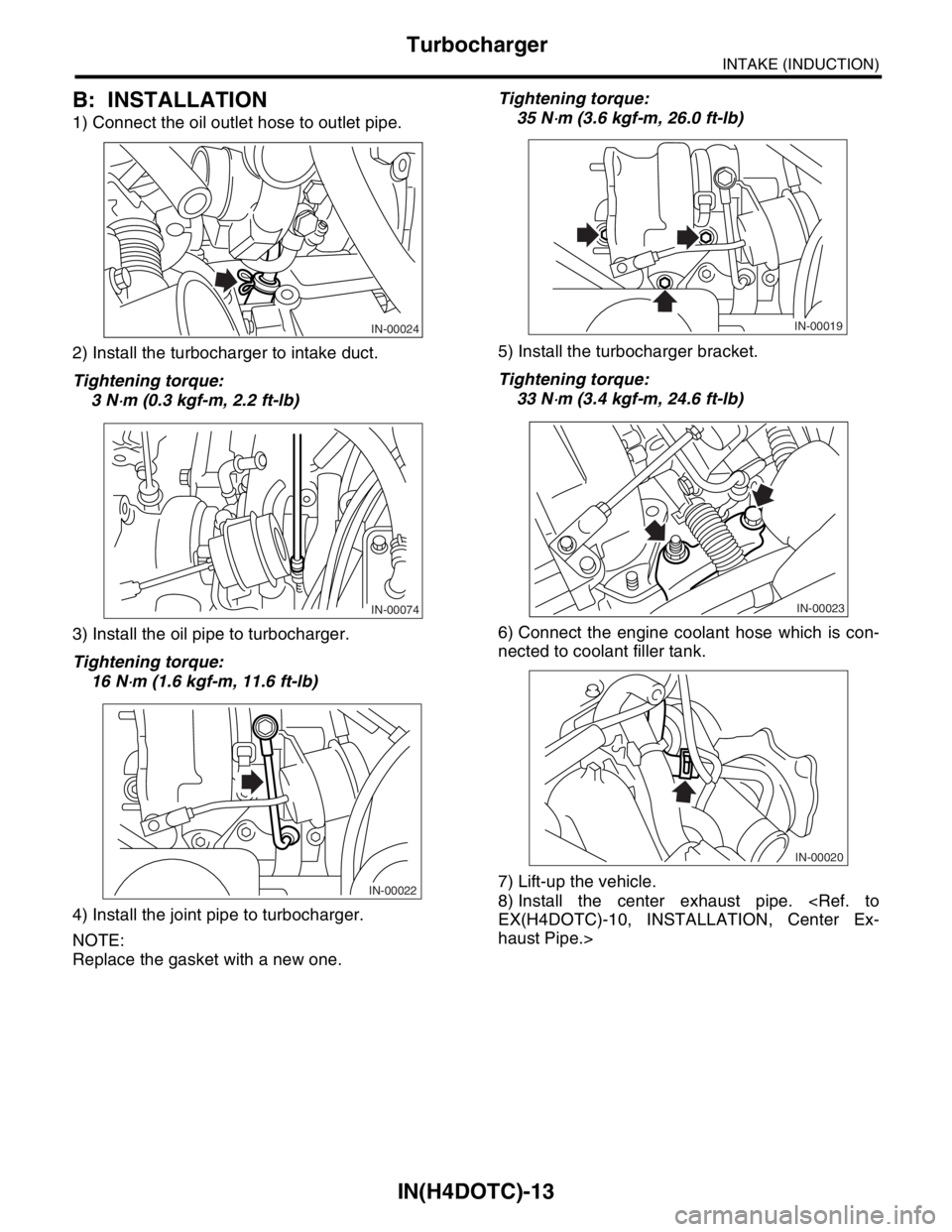
1) Connect the oil outlet hose to outlet pipe.
2) Install the turbocharger to intake duct.
Tightening torque:
3 N
⋅m (0.3 kgf-m, 2.2 ft-lb)
3) Install the oil pipe to turbocharger.
Tightening torque:
16 N
⋅m (1.6 kgf-m, 11.6 ft-lb)
4) Install the joint pipe to turbocharger.
NOTE:
Replace the gasket with a new one.Tightening torque:
35 N
⋅m (3.6 kgf-m, 26.0 ft-lb)
5) Install the turbocharger bracket.
Tightening torque:
33 N
⋅m (3.4 kgf-m, 24.6 ft-lb)
6) Connect the engine coolant hose which is con-
nected to coolant filler tank.
7) Lift-up the vehicle.
8) Install the center exhaust pipe.
haust Pipe.>
IN-00024
IN-00074
IN-00022
IN-00019
IN-00023
IN-00020
Page 1457 of 2870

MECHANICAL
ME(H4DOTC)
Page
1. General Description ....................................................................................2
2. Compression .............................................................................................31
3. Idle Speed .................................................................................................32
4. Ignition Timing ...........................................................................................33
5. Intake Manifold Vacuum............................................................................34
6. Engine Oil Pressure ..................................................................................35
7. Fuel Pressure ............................................................................................36
8. Valve Clearance ........................................................................................37
9. Engine Assembly ......................................................................................41
10. Engine Mounting .......................................................................................50
11. Preparation for Overhaul ...........................................................................51
12. V-belt .........................................................................................................52
13. Crank Pulley ..............................................................................................55
14. Timing Belt Cover......................................................................................57
15. Timing Belt Assembly................................................................................58
16. Cam Sprocket ...........................................................................................67
17. Crank Sprocket .........................................................................................68
18. Camshaft ...................................................................................................69
19. Cylinder Head Assembly ...........................................................................76
20. Cylinder Block ...........................................................................................84
21. Intake and Exhaust Valve .......................................................................115
22. Piston ......................................................................................................116
23. Connecting Rod ......................................................................................117
24. Crankshaft ...............................................................................................118
25. Engine Trouble in General ......................................................................119
26. Engine Noise ...........................................................................................124
Page 1458 of 2870

ME(H4DOTC)-2
MECHANICAL
General Description
1. General Description
A: SPECIFICATION
1. 2.0 L MODEL
NOTE:
STD: Standard I.D.: Inner Diameter O.D.: Outer Diameter OS: Oversize US: Undersize
EngineTy p eHorizontally opposed, liquid cooled, 4-cylinder, 4-stroke
gasoline engine
Valve arrangement Belt driven, double overhead camshaft, 4-valve/cylinder
Bore×Stroke mm (in) 92×75 (3.62×2.95)
Piston displacement
cm
3 (cu in)1,994 (121.67)
Compression ratio 8.0
Compression pres-
sure (at 200 — 300
rpm)kPa (kgf/cm
2, psi)981 — 1,177 (10 — 12, 142 — 171)
Number of piston rings Pressure ring: 2, Oil ring: 1
Intake valve timingOpeningMax. retard BTDC 3°
Min. advance BTDC 33°
ClosingMax. retard ABDC 33°
Min. advance ABDC 3°
Exhaust valve timingOpening BBDC 33°
Closing ATDC 3°
Valve clearanceIntake mm (in) 0.20±0.02 (0.0079±0.0008)
Exhaust mm (in) 0.35±0.02 (0.0138±0.0008)
Idling speed
[At neutral position on MT, or “P” or
“N” range on AT]
rpmNo loadMT: 700±100
AT : 7 0 0±100
A/C ONA/C Refrigerant pressure
(LOW)MT: 725±100
AT : 7 5 0±100
A/C Refrigerant pressure
(HIGH)MT: 800±100
AT : 8 2 5±100
Firing order 1 → 3 → 2 → 4
Ignition timing BTDC/rpm 12°±10°/700
Belt ten-
sion
adjusterProtrusion of adjuster rod 5.7 — 6.7 mm (0.224 — 0.264 in)
Belt ten-
sionerSpacer O.D. 17.955 — 17.975 mm (0.7069 — 0.7077 in)
Tensioner bush I.D. 18.0 — 18.08 mm (0.7087 — 0.7118 in)
Clearance between spacer and bushSTD 0.025 — 0.125 mm (0.0010 — 0.0049 in)
Limit 0.175 mm (0.0069 in)
Side clearance of spacerSTD 0.2 — 0.55 mm (0.0079 — 0.0217 in)
Limit 0.81 mm (0.0319 in)
Page 1462 of 2870

ME(H4DOTC)-6
MECHANICAL
General Description
2. 2.5 L MODEL
NOTE:
STD: Standard I.D.: Inner Diameter O.D.: Outer Diameter OS: Oversize US: Undersize
EngineModel2.5 L
Ty p eHorizontally opposed, liquid cooled, 4-cylinder,
4-stroke gasoline engine
Valve arrangement Belt driven, double overhead camshaft, 4-valve/cylinder
Bore×Stroke mm (in) 99.5×79.0 (3.92×3.11)
Piston displacement
cm
3 (cu in)2,457 (149.94)
Compression ratio 8.2
Compression pres-
sure (at 200 — 300
rpm)kPa (kgf/cm
2, psi)981 — 1,177 (10 — 12, 142 — 171)
Number of piston rings Pressure ring: 2, Oil ring: 1
Intake valve timingOpeningMax. retard ATDC 5°
Min. advance BTDC 15°
ClosingMax. retard ABDC 65°
Min. advance ABDC 45°
Exhaust valve timingOpening BBDC 55°
Closing ATDC 5°
Valve clearanceIntake mm (in) 0.20±0.02 (0.0079±0.0008)
Exhaust mm (in) 0.35±0.02 (0.0138±0.0008)
Idling speed
[At neutral position on MT, or “P” or “N”
range on AT]
rpmNo loadMT: 700±100
AT : 7 0 0±100
A/C ONA/C Refrigerant pressure
(LOW)MT: 725±100
AT : 7 5 0±100
A/C Refrigerant pressure
(HIGH)MT: 800±100
AT : 8 2 5±100
Firing order 1 → 3 → 2 → 4
Ignition timing BTDC/rpmMT model 17°±10°/700
AT model 17°±10°/700
Page 1478 of 2870

ME(H4DOTC)-22
MECHANICAL
General Description
C: CAUTION
Wear working clothing, including a cap, protec-
tive goggles, and protective shoes during opera-
tion.
Remove contamination including dirt and corro-
sion before removal, installation or disassembly.
Keep the disassembled parts in order and pro-
tect them from dust or dirt.
Before removal, installation or disassembly, be
sure to clarify the failure. Avoid unnecessary re-
moval, installation, disassembly, and replacement.
Be careful not to burn yourself, because each
part in the vehicle is hot after running.
Be sure to tighten fasteners including bolts and
nuts to the specified torque.
Place shop jacks or rigid racks at the specified
points.
Before disconnecting electrical connectors of
sensors or units, be sure to disconnect the ground
cable from battery.
All parts should be thoroughly cleaned, paying
special attention to the engine oil passages, pis-
tons and bearings.
Rotating parts and sliding parts such as piston,
bearing and gear should be coated with oil prior to
assembly.
Be careful not to let oil, grease or coolant contact
the timing belt, clutch disc and flywheel.
All removed parts, if to be reused, should be re-
installed in the original positions and directions.
Bolts, nuts and washers should be replaced with
new ones as required.
Even if necessary inspections have been made
in advance, proceed with assembly work while
making rechecks.
Remove or install the engine in an area where
chain hoists, lifting devices, etc. are available for
ready use.
Be sure not to damage coated surfaces of body
panels with tools or stain seats and windows with
coolant or oil. Place a cover over fenders, as re-
quired, for protection.
Prior to starting work, prepare the following:
Service tools, clean cloth, containers to catch cool-
ant and oil, wire ropes, chain hoist, transmission
jacks, etc.
Lift-up or lower the vehicle when necessary.
Make sure to support the correct positions.
Page 1480 of 2870
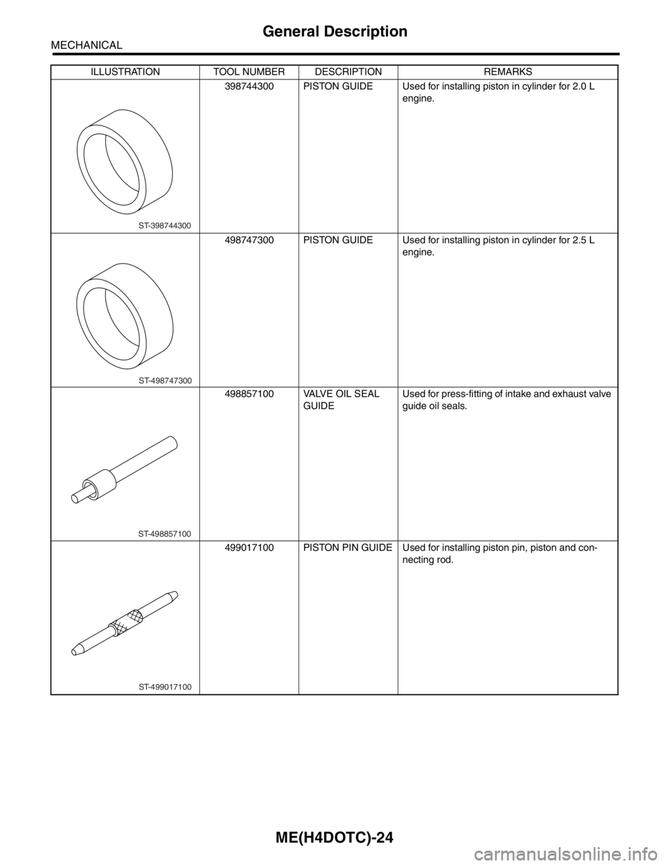
ME(H4DOTC)-24
MECHANICAL
General Description
398744300 PISTON GUIDE Used for installing piston in cylinder for 2.0 L
engine.
498747300 PISTON GUIDE Used for installing piston in cylinder for 2.5 L
engine.
498857100 VALVE OIL SEAL
GUIDEUsed for press-fitting of intake and exhaust valve
guide oil seals.
499017100 PISTON PIN GUIDE Used for installing piston pin, piston and con-
necting rod. ILLUSTRATION TOOL NUMBER DESCRIPTION REMARKS
ST-398744300
ST-498747300
ST-498857100
ST-499017100
Page 1485 of 2870
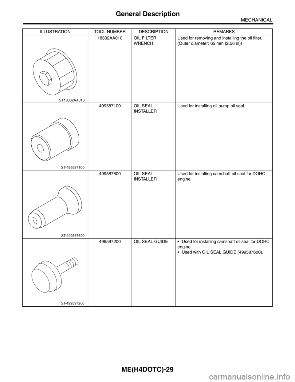
ME(H4DOTC)-29
MECHANICAL
General Description
18332AA010 OIL FILTER
WRENCHUsed for removing and installing the oil filter.
(Outer diameter: 65 mm (2.56 in))
499587100 OIL SEAL
INSTALLERUsed for installing oil pump oil seal.
499587600 OIL SEAL
INSTALLERUsed for installing camshaft oil seal for DOHC
engine.
499597200 OIL SEAL GUIDE Used for installing camshaft oil seal for DOHC
engine.
Used with OIL SEAL GUIDE (499587600). ILLUSTRATION TOOL NUMBER DESCRIPTION REMARKS
ST18332AA010
ST-499587100
ST-499587600
ST-499597200