engine oil SUBARU FORESTER 2004 Service Repair Manual
[x] Cancel search | Manufacturer: SUBARU, Model Year: 2004, Model line: FORESTER, Model: SUBARU FORESTER 2004Pages: 2870, PDF Size: 38.67 MB
Page 1491 of 2870
ME(H4DOTC)-35
MECHANICAL
Engine Oil Pressure
6. Engine Oil Pressure
A: INSPECTION
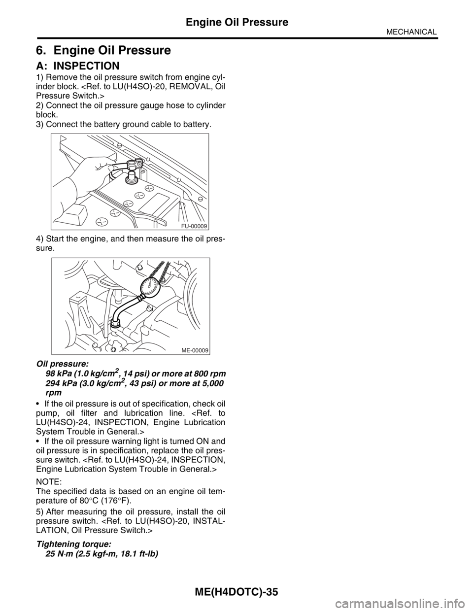
1) Remove the oil pressure switch from engine cyl-
inder block.
2) Connect the oil pressure gauge hose to cylinder
block.
3) Connect the battery ground cable to battery.
4) Start the engine, and then measure the oil pres-
sure.
Oil pressure:
98 kPa (1.0 kg/cm
2, 14 psi) or more at 800 rpm
294 kPa (3.0 kg/cm2, 43 psi) or more at 5,000
rpm
If the oil pressure is out of specification, check oil
pump, oil filter and lubrication line.
System Trouble in General.>
If the oil pressure warning light is turned ON and
oil pressure is in specification, replace the oil pres-
sure switch.
NOTE:
The specified data is based on an engine oil tem-
perature of 80°C (176°F).
5) After measuring the oil pressure, install the oil
pressure switch.
Tightening torque:
25 N
⋅m (2.5 kgf-m, 18.1 ft-lb)
FU-00009
ME-00009
Page 1493 of 2870
ME(H4DOTC)-37
MECHANICAL
Valve Clearance
8. Valve Clearance
A: INSPECTION
Inspection and adjustment of the valve clearance
should be performed while engine is cold.
1) Set the vehicle on a lift.
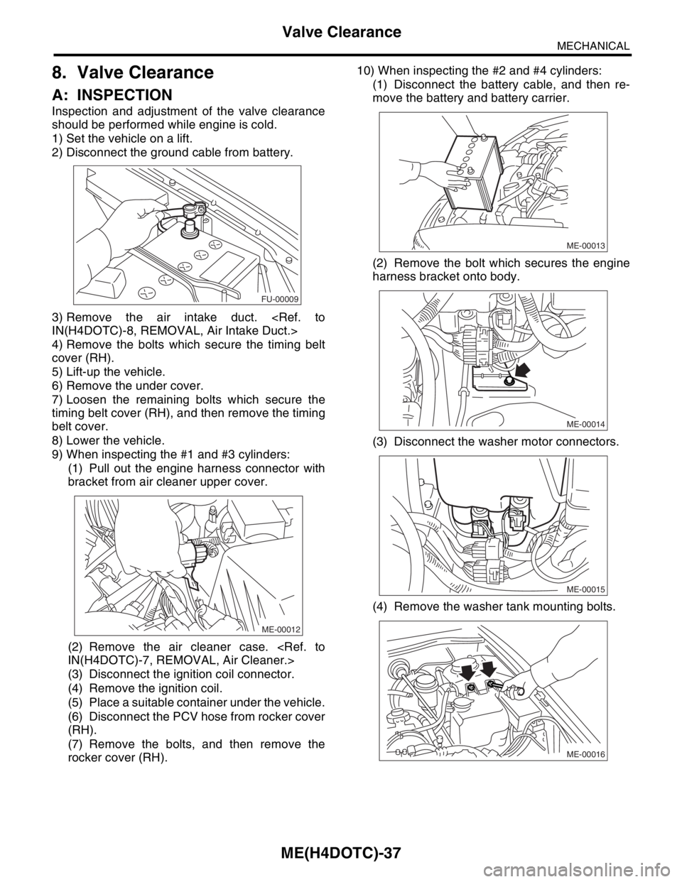
2) Disconnect the ground cable from battery.
3) Remove the air intake duct.
4) Remove the bolts which secure the timing belt
cover (RH).
5) Lift-up the vehicle.
6) Remove the under cover.
7) Loosen the remaining bolts which secure the
timing belt cover (RH), and then remove the timing
belt cover.
8) Lower the vehicle.
9) When inspecting the #1 and #3 cylinders:
(1) Pull out the engine harness connector with
bracket from air cleaner upper cover.
(2) Remove the air cleaner case.
(3) Disconnect the ignition coil connector.
(4) Remove the ignition coil.
(5) Place a suitable container under the vehicle.
(6) Disconnect the PCV hose from rocker cover
(RH).
(7) Remove the bolts, and then remove the
rocker cover (RH).10) When inspecting the #2 and #4 cylinders:
(1) Disconnect the battery cable, and then re-
move the battery and battery carrier.
(2) Remove the bolt which secures the engine
harness bracket onto body.
(3) Disconnect the washer motor connectors.
(4) Remove the washer tank mounting bolts.
FU-00009
ME-00012
ME-00013
ME-00014
ME-00015
ME-00016
Page 1498 of 2870

MECHANICAL
ME(H4DOTC)
Page
1. General Description ....................................................................................2
2. Compression .............................................................................................31
3. Idle Speed .................................................................................................32
4. Ignition Timing ...........................................................................................33
5. Intake Manifold Vacuum............................................................................34
6. Engine Oil Pressure ..................................................................................35
7. Fuel Pressure ............................................................................................36
8. Valve Clearance ........................................................................................37
9. Engine Assembly ......................................................................................41
10. Engine Mounting .......................................................................................50
11. Preparation for Overhaul ...........................................................................51
12. V-belt .........................................................................................................52
13. Crank Pulley ..............................................................................................55
14. Timing Belt Cover......................................................................................57
15. Timing Belt Assembly................................................................................58
16. Cam Sprocket ...........................................................................................67
17. Crank Sprocket .........................................................................................68
18. Camshaft ...................................................................................................69
19. Cylinder Head Assembly ...........................................................................76
20. Cylinder Block ...........................................................................................84
21. Intake and Exhaust Valve .......................................................................115
22. Piston ......................................................................................................116
23. Connecting Rod ......................................................................................117
24. Crankshaft ...............................................................................................118
25. Engine Trouble in General ......................................................................119
26. Engine Noise ...........................................................................................124
Page 1503 of 2870
ME(H4DOTC)-45
MECHANICAL
Engine Assembly
26) Support the transmission with a garage jack.
NOTE:
Before moving the engine away from transmission,
check to be sure no work has been overlooked. Do-
ing this is very important in order to facilitate re-in-
stallation and because transmission lowers under
its own weight.
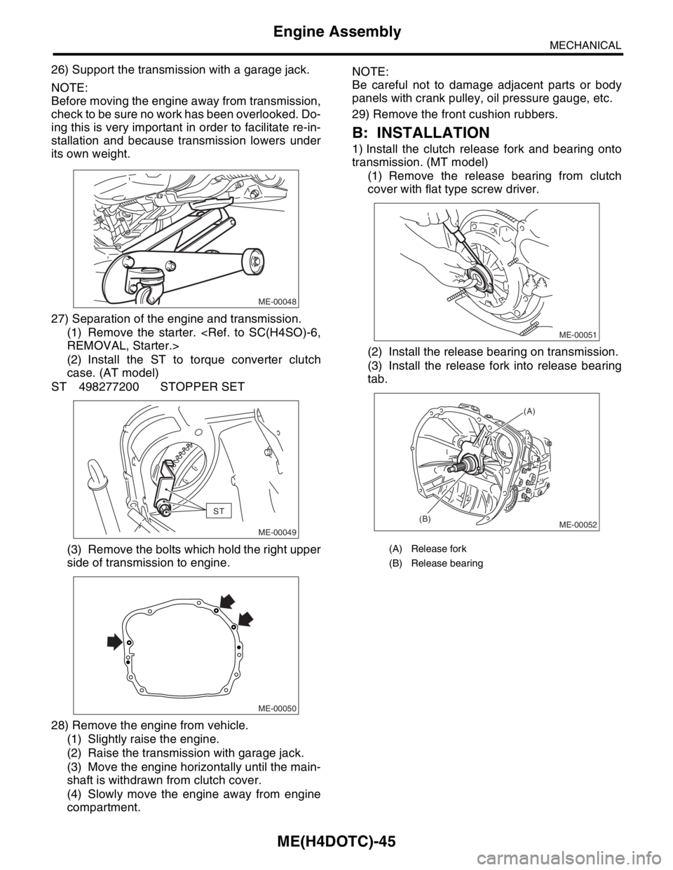
27) Separation of the engine and transmission.
(1) Remove the starter.
(2) Install the ST to torque converter clutch
case. (AT model)
ST 498277200 STOPPER SET
(3) Remove the bolts which hold the right upper
side of transmission to engine.
28) Remove the engine from vehicle.
(1) Slightly raise the engine.
(2) Raise the transmission with garage jack.
(3) Move the engine horizontally until the main-
shaft is withdrawn from clutch cover.
(4) Slowly move the engine away from engine
compartment.NOTE:
Be careful not to damage adjacent parts or body
panels with crank pulley, oil pressure gauge, etc.
29) Remove the front cushion rubbers.
B: INSTALLATION
1) Install the clutch release fork and bearing onto
transmission. (MT model)
(1) Remove the release bearing from clutch
cover with flat type screw driver.
(2) Install the release bearing on transmission.
(3) Install the release fork into release bearing
tab.
ME-00048
ST
ME-00049
ME-00050
(A) Release fork
(B) Release bearing
ME-00051
ME-00052
(A)
(B)
Page 1504 of 2870
ME(H4DOTC)-46
MECHANICAL
Engine Assembly
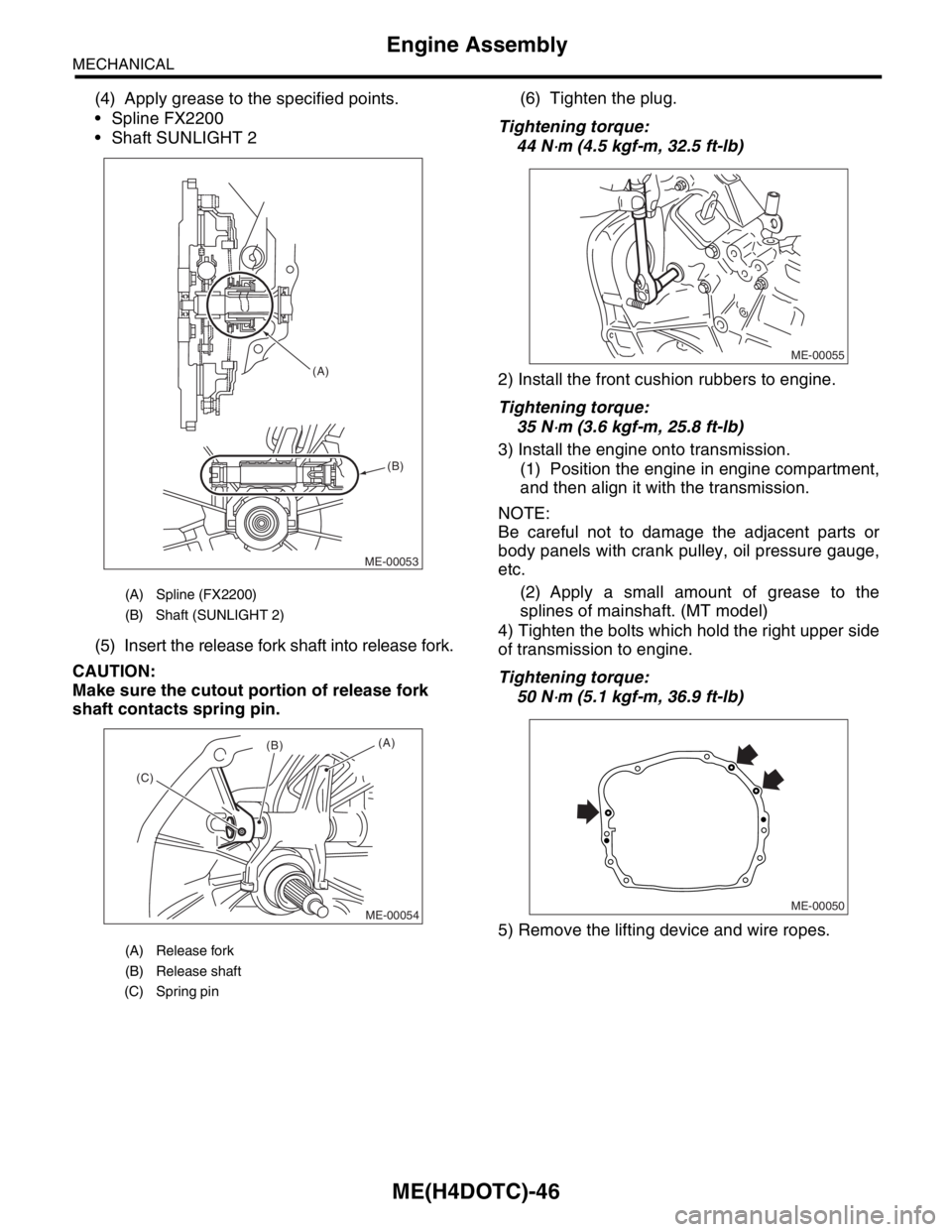
(4) Apply grease to the specified points.
Spline FX2200
Shaft SUNLIGHT 2
(5) Insert the release fork shaft into release fork.
CAUTION:
Make sure the cutout portion of release fork
shaft contacts spring pin.(6) Tighten the plug.
Tightening torque:
44 N
⋅m (4.5 kgf-m, 32.5 ft-lb)
2) Install the front cushion rubbers to engine.
Tightening torque:
35 N
⋅m (3.6 kgf-m, 25.8 ft-lb)
3) Install the engine onto transmission.
(1) Position the engine in engine compartment,
and then align it with the transmission.
NOTE:
Be careful not to damage the adjacent parts or
body panels with crank pulley, oil pressure gauge,
etc.
(2) Apply a small amount of grease to the
splines of mainshaft. (MT model)
4) Tighten the bolts which hold the right upper side
of transmission to engine.
Tightening torque:
50 N
⋅m (5.1 kgf-m, 36.9 ft-lb)
5) Remove the lifting device and wire ropes.
(A) Spline (FX2200)
(B) Shaft (SUNLIGHT 2)
(A) Release fork
(B) Release shaft
(C) Spring pin
ME-00053 (A)
(B)
ME-00054
(A)(B)
(C)ME-00055
ME-00050
Page 1513 of 2870
ME(H4DOTC)-55
MECHANICAL
Crank Pulley
13.Crank Pulley
A: REMOVAL
1) Remove the V-belt.
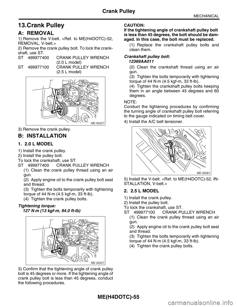
2) Remove the crank pulley bolt. To lock the crank-
shaft, use ST.
ST 499977400 CRANK PULLEY WRENCH
(2.0 L model)
ST 499977100 CRANK PULLEY WRENCH
(2.5 L model)
3) Remove the crank pulley.
B: INSTALLATION
1. 2.0 L MODEL
1) Install the crank pulley.
2) Install the pulley bolt.
To lock the crankshaft, use ST.
ST 499977400 CRANK PULLEY WRENCH
(1) Clean the crank pulley thread using an air
gun.
(2) Apply engine oil to the crank pulley bolt seat
and thread.
(3) Tighten the bolts temporarily with tightening
torque of 44 N⋅m (4.5 kgf-m, 33 ft-lb).
(4) Tighten the crank pulley bolts.
Tightening torque:
127 N
⋅m (13 kgf-m, 94.0 ft-lb)
3) Confirm that the tightening angle of crank pulley
bolt is 45 degrees or more. If the tightening angle of
crank pulley bolt is less than 45 degrees, conduct
the following procedures.CAUTION:
If the tightening angle of crankshaft pulley bolt
is less than 45 degrees, the bolt should be dam-
aged. In this case, the bolt must be replaced.
(1) Replace the crankshaft pulley bolts and
clean them.
Crankshaft pulley bolt:
12369AA011
(2) Clean the crankshaft thread using an air
gun.
(3) Tighten the bolts temporarily with tightening
torque of 44 N⋅m (4.5 kgf-m, 33 ft-lb).
(4) Tighten the crankshaft pulley bolts keeping
them in an angle between 45 degrees and 60
degrees.
NOTE:
Conduct the tightening procedures by confirming
the turning angle of crankshaft pulley bolt referring
to the gauge indicated on timing belt cover.
4) Install the A/C belt tensioner.
5) Install the V-belt.
2. 2.5 L MODEL
1) Install the crank pulley.
2) Install the pulley bolt.
To lock the crankshaft, use ST.
ST 499977100 CRANK PULLEY WRENCH
(1) Clean the crank pulley thread using an air
gun.
(2) Apply engine oil to the crank pulley bolt seat
and thread.
(3) Tighten the bolts temporarily with tightening
torque of 44 N⋅m (4.5 kgf-m, 33 ft-lb).
(4) Tighten the crank pulley bolts.
ME-00227
STST
ME-00227
STST
ME-00061
Page 1514 of 2870
ME(H4DOTC)-56
MECHANICAL
Crank Pulley
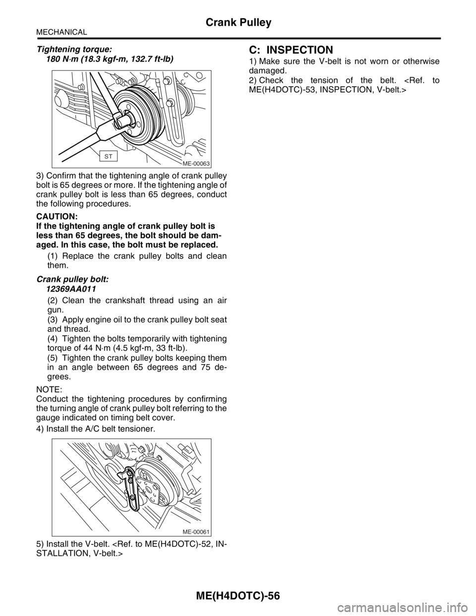
Tightening torque:
180 N
⋅m (18.3 kgf-m, 132.7 ft-lb)
3) Confirm that the tightening angle of crank pulley
bolt is 65 degrees or more. If the tightening angle of
crank pulley bolt is less than 65 degrees, conduct
the following procedures.
CAUTION:
If the tightening angle of crank pulley bolt is
less than 65 degrees, the bolt should be dam-
aged. In this case, the bolt must be replaced.
(1) Replace the crank pulley bolts and clean
them.
Crank pulley bolt:
12369AA011
(2) Clean the crankshaft thread using an air
gun.
(3) Apply engine oil to the crank pulley bolt seat
and thread.
(4) Tighten the bolts temporarily with tightening
torque of 44 N⋅m (4.5 kgf-m, 33 ft-lb).
(5) Tighten the crank pulley bolts keeping them
in an angle between 65 degrees and 75 de-
grees.
NOTE:
Conduct the tightening procedures by confirming
the turning angle of crank pulley bolt referring to the
gauge indicated on timing belt cover.
4) Install the A/C belt tensioner.
5) Install the V-belt.
C: INSPECTION
1) Make sure the V-belt is not worn or otherwise
damaged.
2) Check the tension of the belt.
ME-00063ST
ME-00061
Page 1527 of 2870
ME(H4DOTC)-69
MECHANICAL
Camshaft
16) Remove the oil flow control solenoid valve as-
sembly, intake camshaft cap, and camshaft.
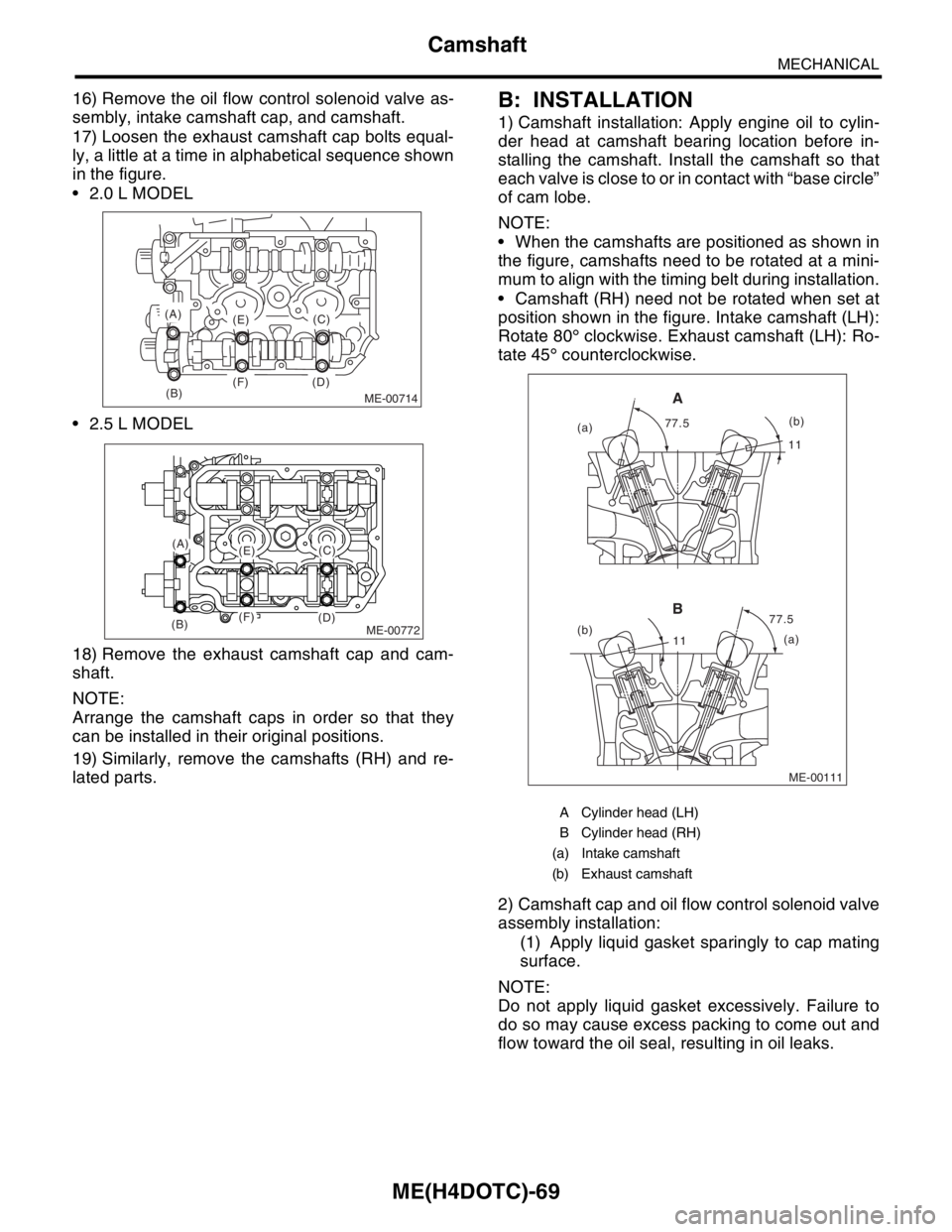
17) Loosen the exhaust camshaft cap bolts equal-
ly, a little at a time in alphabetical sequence shown
in the figure.
2.0 L MODEL
2.5 L MODEL
18) Remove the exhaust camshaft cap and cam-
shaft.
NOTE:
Arrange the camshaft caps in order so that they
can be installed in their original positions.
19) Similarly, remove the camshafts (RH) and re-
lated parts.B: INSTALLATION
1) Camshaft installation: Apply engine oil to cylin-
der head at camshaft bearing location before in-
stalling the camshaft. Install the camshaft so that
each valve is close to or in contact with “base circle”
of cam lobe.
NOTE:
When the camshafts are positioned as shown in
the figure, camshafts need to be rotated at a mini-
mum to align with the timing belt during installation.
Camshaft (RH) need not be rotated when set at
position shown in the figure. Intake camshaft (LH):
Rotate 80° clockwise. Exhaust camshaft (LH): Ro-
tate 45° counterclockwise.
2) Camshaft cap and oil flow control solenoid valve
assembly installation:
(1) Apply liquid gasket sparingly to cap mating
surface.
NOTE:
Do not apply liquid gasket excessively. Failure to
do so may cause excess packing to come out and
flow toward the oil seal, resulting in oil leaks.
ME-00714(B)
(A)
(E)
(F) (D)(C)
ME-00772
(A)(E)
(F)(B)(D)
(C)
A Cylinder head (LH)
B Cylinder head (RH)
(a) Intake camshaft
(b) Exhaust camshaft
ME-00111
1111
77.5 77.5
(a)
(b)
(a)(b)
A
B
Page 1528 of 2870
ME(H4DOTC)-70
MECHANICAL
Camshaft
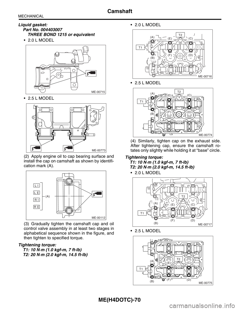
Liquid gasket:
Part No. 004403007
THREE BOND 1215 or equivalent
2.0 L MODEL
2.5 L MODEL
(2) Apply engine oil to cap bearing surface and
install the cap on camshaft as shown by identifi-
cation mark (A).
(3) Gradually tighten the camshaft cap and oil
control valve assembly in at least two stages in
alphabetical sequence shown in the figure, and
then tighten to specified torque.
Tightening torque:
T1: 10 N
⋅m (1.0 kgf-m, 7 ft-lb)
T2: 20 N
⋅m (2.0 kgf-m, 14.5 ft-lb) 2.0 L MODEL
2.5 L MODEL
(4) Similarly, tighten cap on the exhaust side.
After tightening cap, ensure the camshaft ro-
tates only slightly while holding it at “base” circle.
Tightening torque:
T1: 10 N
⋅m (1.0 kgf-m, 7 ft-lb)
T2: 20 N
⋅m (2.0 kgf-m, 14.5 ft-lb)
2.0 L MODEL
2.5 L MODEL
ME-00715
ME-00773
ME-00112
L E
R E
R I
L I
(A)
(B)
(A)
(E)
(F) (D)(C)
T1
ME-00716
T2
ME-00774
(A)(E)
(F)(B)(D)
(C)T2
T1
ME-00717(B)
(A)
(E)
(F) (D)(C)
T2
T1
ME-00775
(A)(E)
(F)(B)(D)
(C)T2
T1
Page 1533 of 2870

ME(H4DOTC)-75
MECHANICAL
Cylinder Head Assembly
19.Cylinder Head Assembly
A: REMOVAL
1) Remove the V-belt.
2) Remove the crank pulley.
3) Remove the timing belt cover.
4) Remove the timing belt assembly.
bly.>
5) Remove the cam sprocket.
6) Remove the intake manifold.
7) Remove the bolt which installs the A/C compres-
sor bracket on cylinder head.
8) Remove the camshaft.
9) Remove the cylinder head bolts in alphabetical
sequence shown in the figure.
Leave bolts (A) and (D) engaged by three or four
threads to prevent the cylinder head from falling.
10) While tapping the cylinder head with a plastic
hammer, separate it from cylinder block. Remove
the bolts (A) and (D) to remove cylinder head.11) Remove the cylinder head gasket.
NOTE:
Do not scratch the mating surface of cylinder head
and cylinder block.
12) Similarly, remove the cylinder head (RH).
B: INSTALLATION
1) Install the cylinder head and gaskets on cylinder
block.
NOTE:
Use new cylinder head gaskets.
Be careful not to scratch the mating surface of
cylinder head and cylinder block.
2) Tighten the cylinder head bolts.
(1) Apply a coat of engine oil to the washers and
bolt threads.
(2) Tighten all bolts to 29 N⋅m (3.0 kgf-m, 22 ft-
lb) in alphabetical sequence.
(3) Tighten all bolts to 69 N⋅m (7.0 kgf-m, 51 ft-
lb) in alphabetical sequence again.
(4) Back off all bolts by 180° first; back them off
by 180° again in reverse order of installation.
(5) Tighten all bolts to 49 N⋅m (5.0 kgf-m, 36 ft-
lb) in alphabetical sequence.
(6) Tighten all bolts 80 to 90° in alphabetical se-
quence.
(7) Tighten all bolts by 40 to 45° in alphabetical
sequence again.
NOTE:
Do not tighten the bolts by more than 45°.
(8) Further tighten all bolts (A) and (B) by 40 to
45°.
NOTE:
Ensure that the total “re-tightening angle” in the
previous two steps do not exceed 90°.
3) Install the camshaft.
4) Install the A/C compressor bracket on cylinder
head.
5) Install the intake manifold.
6) Install the cam sprocket.
ME-00122
(B)(C)
(D)
(E)
(F)(A)
ME-00122
(B)(C)
(D)
(E)
(F)(A)
ME-00123
(B)
(C)
(D)(E)
(F)(A)