driver SUBARU FORESTER 2004 Service Repair Manual
[x] Cancel search | Manufacturer: SUBARU, Model Year: 2004, Model line: FORESTER, Model: SUBARU FORESTER 2004Pages: 2870, PDF Size: 38.67 MB
Page 2434 of 2870
4AT-120
AUTOMATIC TRANSMISSION
Front Differential
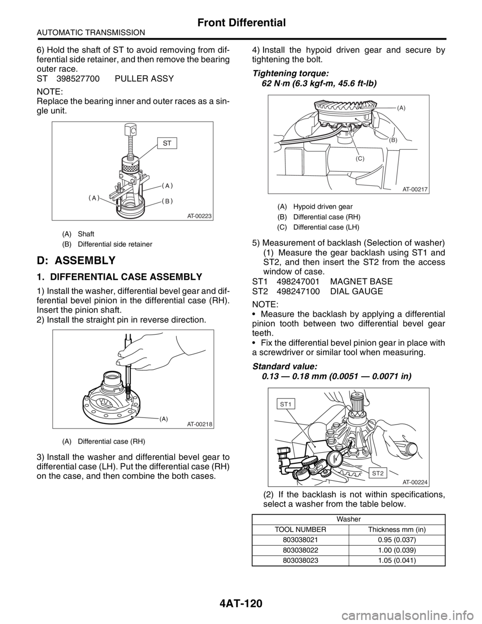
6) Hold the shaft of ST to avoid removing from dif-
ferential side retainer, and then remove the bearing
outer race.
ST 398527700 PULLER ASSY
NOTE:
Replace the bearing inner and outer races as a sin-
gle unit.
D: ASSEMBLY
1. DIFFERENTIAL CASE ASSEMBLY
1) Install the washer, differential bevel gear and dif-
ferential bevel pinion in the differential case (RH).
Insert the pinion shaft.
2) Install the straight pin in reverse direction.
3) Install the washer and differential bevel gear to
differential case (LH). Put the differential case (RH)
on the case, and then combine the both cases.4) Install the hypoid driven gear and secure by
tightening the bolt.
Tightening torque:
62 N
⋅m (6.3 kgf-m, 45.6 ft-lb)
5) Measurement of backlash (Selection of washer)
(1) Measure the gear backlash using ST1 and
ST2, and then insert the ST2 from the access
window of case.
ST1 498247001 MAGNET BASE
ST2 498247100 DIAL GAUGE
NOTE:
Measure the backlash by applying a differential
pinion tooth between two differential bevel gear
teeth.
Fix the differential bevel pinion gear in place with
a screwdriver or similar tool when measuring.
Standard value:
0.13 — 0.18 mm (0.0051 — 0.0071 in)
(2) If the backlash is not within specifications,
select a washer from the table below.
(A) Shaft
(B) Differential side retainer
(A) Differential case (RH)
AT-00223
AT-00218(A)
(A) Hypoid driven gear
(B) Differential case (RH)
(C) Differential case (LH)
Washer
TOOL NUMBER Thickness mm (in)
803038021 0.95 (0.037)
803038022 1.00 (0.039)
803038023 1.05 (0.041)
(B)
AT-00217
(A)
(C)
AT-00224
ST2
ST1
Page 2476 of 2870
4AT(H4SO)-17
AUTOMATIC TRANSMISSION (DIAGNOSTIC)
Subaru Select Monitor
6. Subaru Select Monitor
A: OPERATION
1. READ DIAGNOSTIC TROUBLE CODE
(DTC)
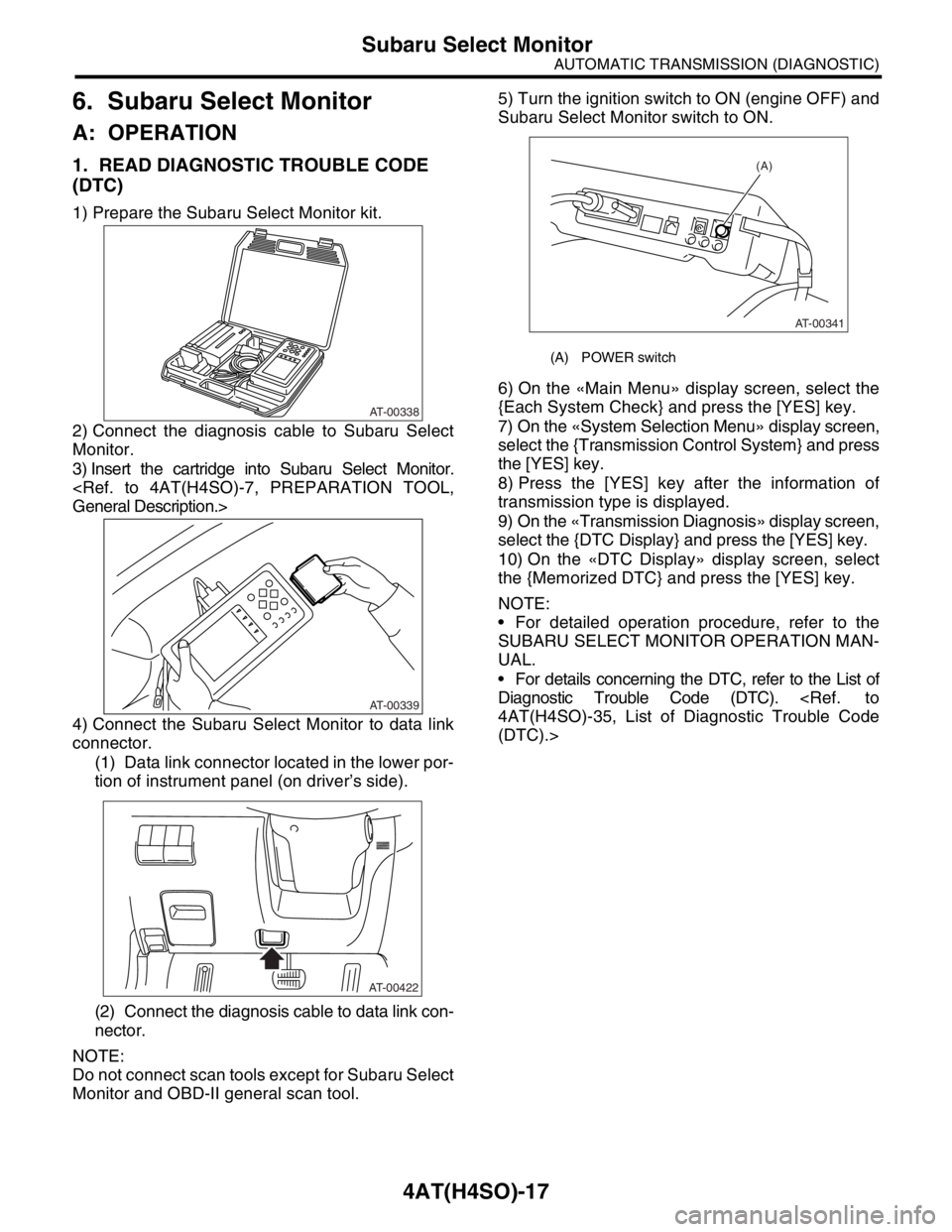
1) Prepare the Subaru Select Monitor kit.
2) Connect the diagnosis cable to Subaru Select
Monitor.
3) Insert the cartridge into Subaru Select Monitor.
4) Connect the Subaru Select Monitor to data link
connector.
(1) Data link connector located in the lower por-
tion of instrument panel (on driver’s side).
(2) Connect the diagnosis cable to data link con-
nector.
NOTE:
Do not connect scan tools except for Subaru Select
Monitor and OBD-II general scan tool.5) Turn the ignition switch to ON (engine OFF) and
Subaru Select Monitor switch to ON.
6) On the «Main Menu» display screen, select the
{Each System Check} and press the [YES] key.
7) On the «System Selection Menu» display screen,
select the {Transmission Control System} and press
the [YES] key.
8) Press the [YES] key after the information of
transmission type is displayed.
9) On the «Transmission Diagnosis» display screen,
select the {DTC Display} and press the [YES] key.
10) On the «DTC Display» display screen, select
the {Memorized DTC} and press the [YES] key.
NOTE:
For detailed operation procedure, refer to the
SUBARU SELECT MONITOR OPERATION MAN-
UAL.
For details concerning the DTC, refer to the List of
Diagnostic Trouble Code (DTC).
(DTC).>
AT-00338
AT-00339
AT-00422
(A) POWER switch
(A)
AT-00341
Page 2591 of 2870
4AT(H4DOTC)-15
AUTOMATIC TRANSMISSION (DIAGNOSTIC)
Subaru Select Monitor
6. Subaru Select Monitor
A: OPERATION
1. READ DIAGNOSTIC TROUBLE CODE
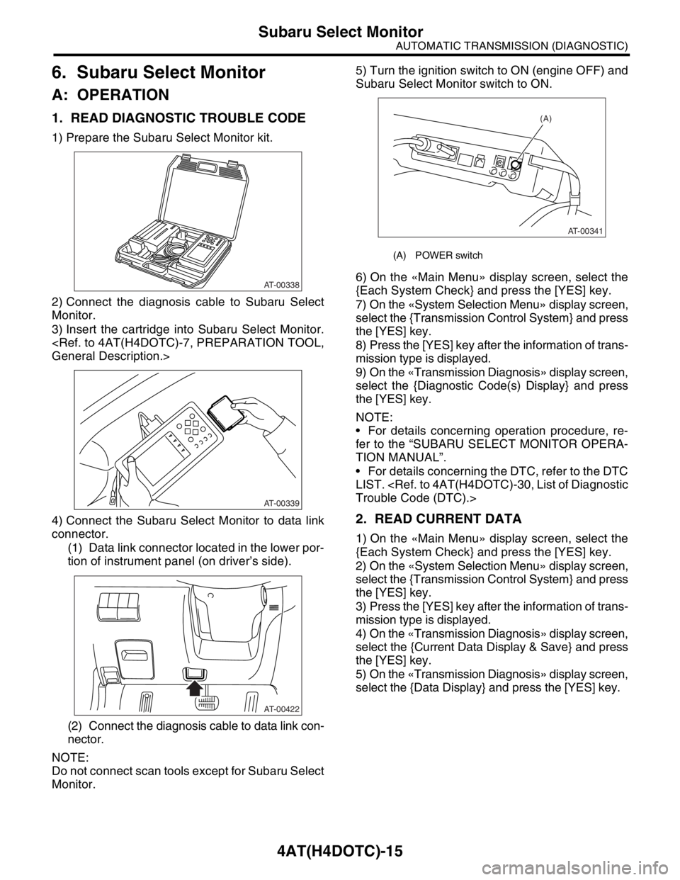
1) Prepare the Subaru Select Monitor kit.
2) Connect the diagnosis cable to Subaru Select
Monitor.
3) Insert the cartridge into Subaru Select Monitor.
4) Connect the Subaru Select Monitor to data link
connector.
(1) Data link connector located in the lower por-
tion of instrument panel (on driver’s side).
(2) Connect the diagnosis cable to data link con-
nector.
NOTE:
Do not connect scan tools except for Subaru Select
Monitor.5) Turn the ignition switch to ON (engine OFF) and
Subaru Select Monitor switch to ON.
6) On the «Main Menu» display screen, select the
{Each System Check} and press the [YES] key.
7) On the «System Selection Menu» display screen,
select the {Transmission Control System} and press
the [YES] key.
8) Press the [YES] key after the information of trans-
mission type is displayed.
9) On the «Transmission Diagnosis» display screen,
select the {Diagnostic Code(s) Display} and press
the [YES] key.
NOTE:
For details concerning operation procedure, re-
fer to the “SUBARU SELECT MONITOR OPERA-
TION MANUAL”.
For details concerning the DTC, refer to the DTC
LIST.
2. READ CURRENT DATA
1) On the «Main Menu» display screen, select the
{Each System Check} and press the [YES] key.
2) On the «System Selection Menu» display screen,
select the {Transmission Control System} and press
the [YES] key.
3) Press the [YES] key after the information of trans-
mission type is displayed.
4) On the «Transmission Diagnosis» display screen,
select the {Current Data Display & Save} and press
the [YES] key.
5) On the «Transmission Diagnosis» display screen,
select the {Data Display} and press the [YES] key.
AT-00338
AT-00339
AT-00422
(A) POWER switch
(A)
AT-00341
Page 2729 of 2870
5MT-17
MANUAL TRANSMISSION AND DIFFERENTIAL
General Description
C: CAUTION
Wear working clothing, including a cap, protec-
tive goggles, and protective shoes during opera-
tion.
Remove contamination including dirt and corro-
sion before removal, installation, and disassembly.
Keep the disassembled parts in order and pro-
tect them from dust or dirt.
Until the oil pan is removed, do not place with the
oil pan side facing up to prevent foreign matter from
entering the valve body.
Before removal, installation or disassembly, be
sure to clarify the failure. Avoid unnecessary re-
moval, installation, disassembly and replacement.
When disassembling the case and other light al-
loy parts, use a plastic hammer to force it apart. Do
not pry it apart with a screwdriver or other tool.
Be careful not to burn your hands, because each
part on the vehicle is hot after running. Use SUBARU genuine gear oil, grease etc. or
the equivalent. Do not mix gear oil, grease etc. with
that of another grade or from other manufacturers.
Be sure to tighten fasteners including bolts and
nuts to the specified torque.
Place shop jacks or rigid racks at the specified
points.
Apply gear oil onto sliding or revolution surfaces
before installation.
Replace deformed or otherwise damaged snap
rings with new ones.
Before installing O-rings or oil seals, apply suffi-
cient amount of gear oil to avoid damage and defor-
mation.
Be careful not to incorrectly install or fail to install
O-rings, snap rings and other such parts.
Before securing a part on a vise, place cushion-
ing material such as wood blocks, aluminum plate,
or shop cloth between the part and the vis e.
Avoid damaging the mating surface of the case.
Before applying sealant, completely remove the
old seal.
D: PREPARATION TOOL
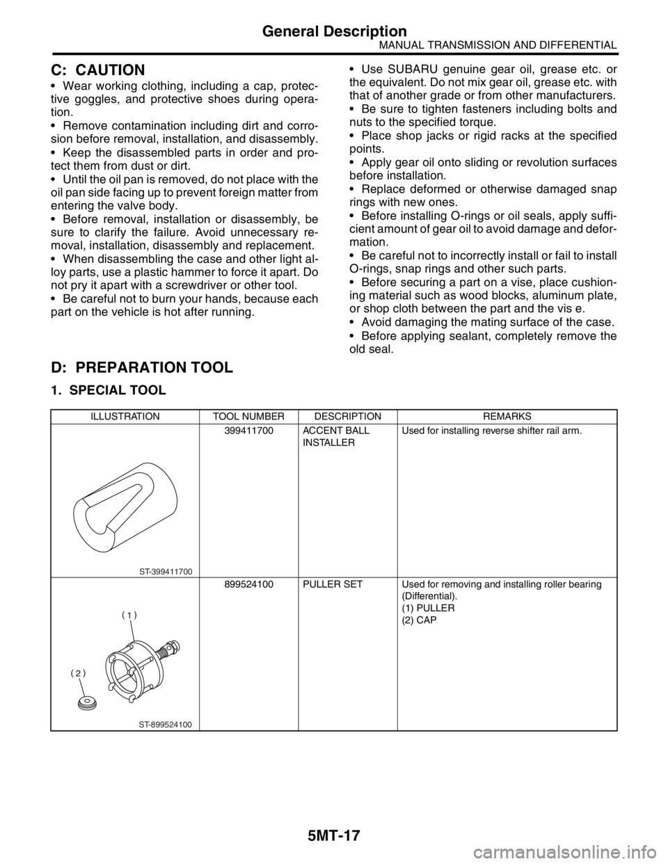
1. SPECIAL TOOL
ILLUSTRATION TOOL NUMBER DESCRIPTION REMARKS
399411700 ACCENT BALL
INSTALLERUsed for installing reverse shifter rail arm.
899524100 PULLER SET Used for removing and installing roller bearing
(Differential).
(1) PULLER
(2) CAP
ST-399411700
ST-899524100
Page 2754 of 2870
5MT-42
MANUAL TRANSMISSION AND DIFFERENTIAL
Differential Side Retainer Oil Seal
6. Differential Side Retainer Oil
Seal
A: INSPECTION
Check the differential side retainer oil seal for leak-
age of gear oil. If oil leaks, replace the oil seal.
B: REPLACEMENT
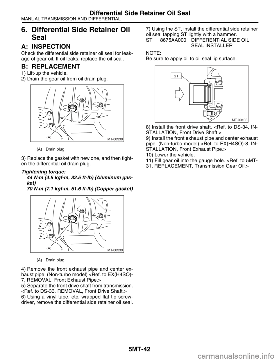
1) Lift-up the vehicle.
2) Drain the gear oil from oil drain plug.
3) Replace the gasket with new one, and then tight-
en the differential oil drain plug.
Tightening torque:
44 N·m (4.5 kgf-m, 32.5 ft-lb) (Aluminum gas-
ket)
70 N·m (7.1 kgf-m, 51.6 ft-lb) (Copper gasket)
4) Remove the front exhaust pipe and center ex-
haust pipe. (Non-turbo model)
5) Separate the front drive shaft from transmission.
6) Using a vinyl tape, etc. wrapped flat tip screw-
driver, remove the differential side retainer oil seal.7) Using the ST, install the differential side retainer
oil seal tapping ST lightly with a hammer.
ST 18675AA000 DIFFERENTIAL SIDE OIL
SEAL INSTALLER
NOTE:
Be sure to apply oil to oil seal lip surface.
8) Install the front drive shaft.
9) Install the front exhaust pipe and center exhaust
pipe. (Non-turbo model)
10) Lower the vehicle.
11) Fill gear oil into the gauge hole.
(A) Drain plug
(A) Drain plug
(A)
MT-00339
(A)
MT-00339
MT-00103
ST
Page 2773 of 2870
5MT-60
MANUAL TRANSMISSION AND DIFFERENTIAL
Reverse Check Sleeve
C: DISASSEMBLY
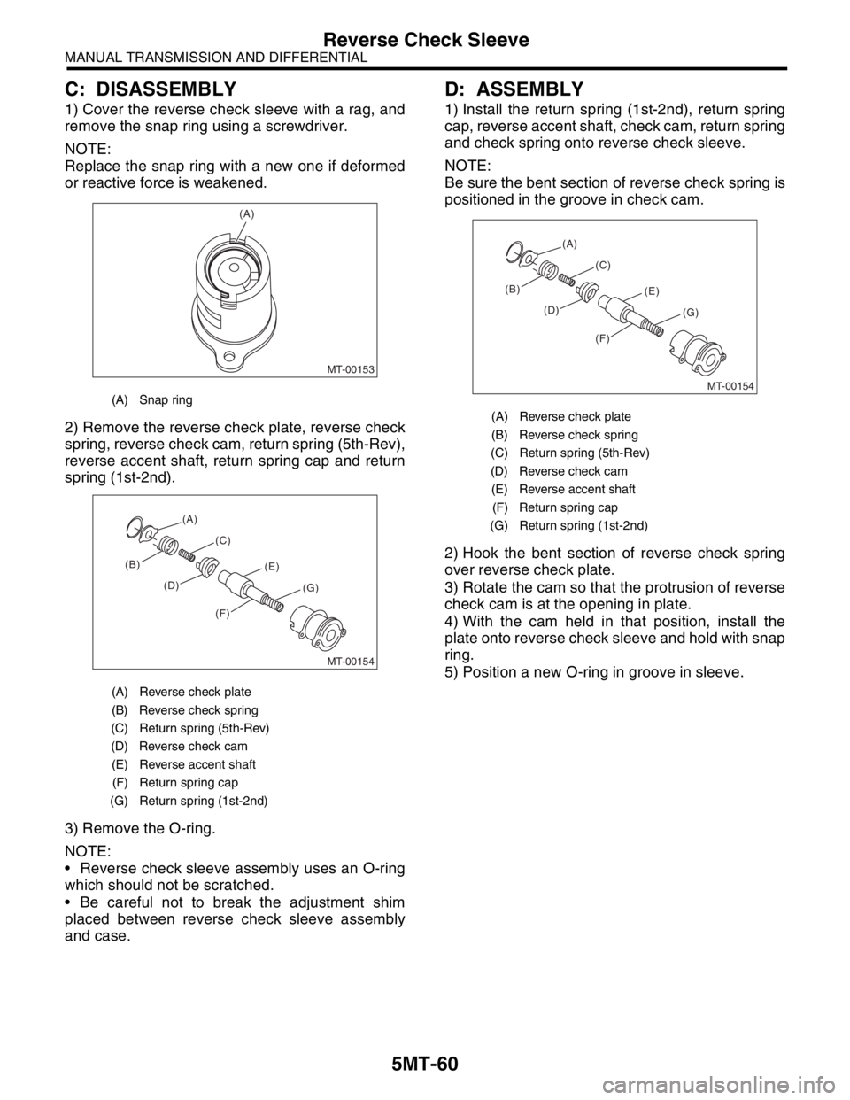
1) Cover the reverse check sleeve with a rag, and
remove the snap ring using a screwdriver.
NOTE:
Replace the snap ring with a new one if deformed
or reactive force is weakened.
2) Remove the reverse check plate, reverse check
spring, reverse check cam, return spring (5th-Rev),
reverse accent shaft, return spring cap and return
spring (1st-2nd).
3) Remove the O-ring.
NOTE:
Reverse check sleeve assembly uses an O-ring
which should not be scratched.
Be careful not to break the adjustment shim
placed between reverse check sleeve assembly
and case.
D: ASSEMBLY
1) Install the return spring (1st-2nd), return spring
cap, reverse accent shaft, check cam, return spring
and check spring onto reverse check sleeve.
NOTE:
Be sure the bent section of reverse check spring is
positioned in the groove in check cam.
2) Hook the bent section of reverse check spring
over reverse check plate.
3) Rotate the cam so that the protrusion of reverse
check cam is at the opening in plate.
4) With the cam held in that position, install the
plate onto reverse check sleeve and hold with snap
ring.
5) Position a new O-ring in groove in sleeve.
(A) Snap ring
(A) Reverse check plate
(B) Reverse check spring
(C) Return spring (5th-Rev)
(D) Reverse check cam
(E) Reverse accent shaft
(F) Return spring cap
(G) Return spring (1st-2nd)
MT-00153
(A)
MT-00154
(B)(C)
(D)(E)
(F)(G) (A)
(A) Reverse check plate
(B) Reverse check spring
(C) Return spring (5th-Rev)
(D) Reverse check cam
(E) Reverse accent shaft
(F) Return spring cap
(G) Return spring (1st-2nd)
MT-00154
(B)(C)
(D)(E)
(F)(G) (A)
Page 2807 of 2870
5MT-94
MANUAL TRANSMISSION AND DIFFERENTIAL
Drive Pinion Shaft Assembly
F: ADJUSTMENT
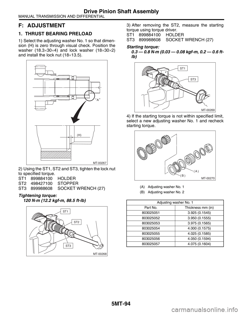
1. THRUST BEARING PRELOAD
1) Select the adjusting washer No. 1 so that dimen-
sion (H) is zero through visual check. Position the
washer (18.3×30×4) and lock washer (18×30×2)
and install the lock nut (18×13.5).
2) Using the ST1, ST2 and ST3, tighten the lock nut
to specified torque.
ST1 899884100 HOLDER
ST2 498427100 STOPPER
ST3 899988608 SOCKET WRENCH (27)
Tightening torque:
120 N·m (12.2 kgf-m, 88.5 ft-lb) 3) After removing the ST2, measure the starting
torque using torque driver.
ST1 899884100 HOLDER
ST3 899988608 SOCKET WRENCH (27)
Starting torque:
0.3 — 0.8 N·m (0.03 — 0.08 kgf-m, 0.2 — 0.6 ft-
lb)
4) If the starting torque is not within specified limit,
select a new adjusting washer No. 1 and recheck
starting torque.
MT-00267 (H)
MT-00268
ST1
ST2
ST3
(A) Adjusting washer No. 1
(B) Adjusting washer No. 2
Adjusting washer No. 1
Part No. Thickness mm (in)
803025051 3.925 (0.1545)
803025052 3.950 (0.1555)
803025053 3.975 (0.1565)
803025054 4.000 (0.1575)
803025055 4.025 (0.1585)
803025056 4.050 (0.1594)
803025057 4.075 (0.1604)
MT-00269
ST1
ST3
MT-00270
(A)
(B)
Page 2811 of 2870
5MT-98
MANUAL TRANSMISSION AND DIFFERENTIAL
Front Differential Assembly
2. SIDE RETAINER
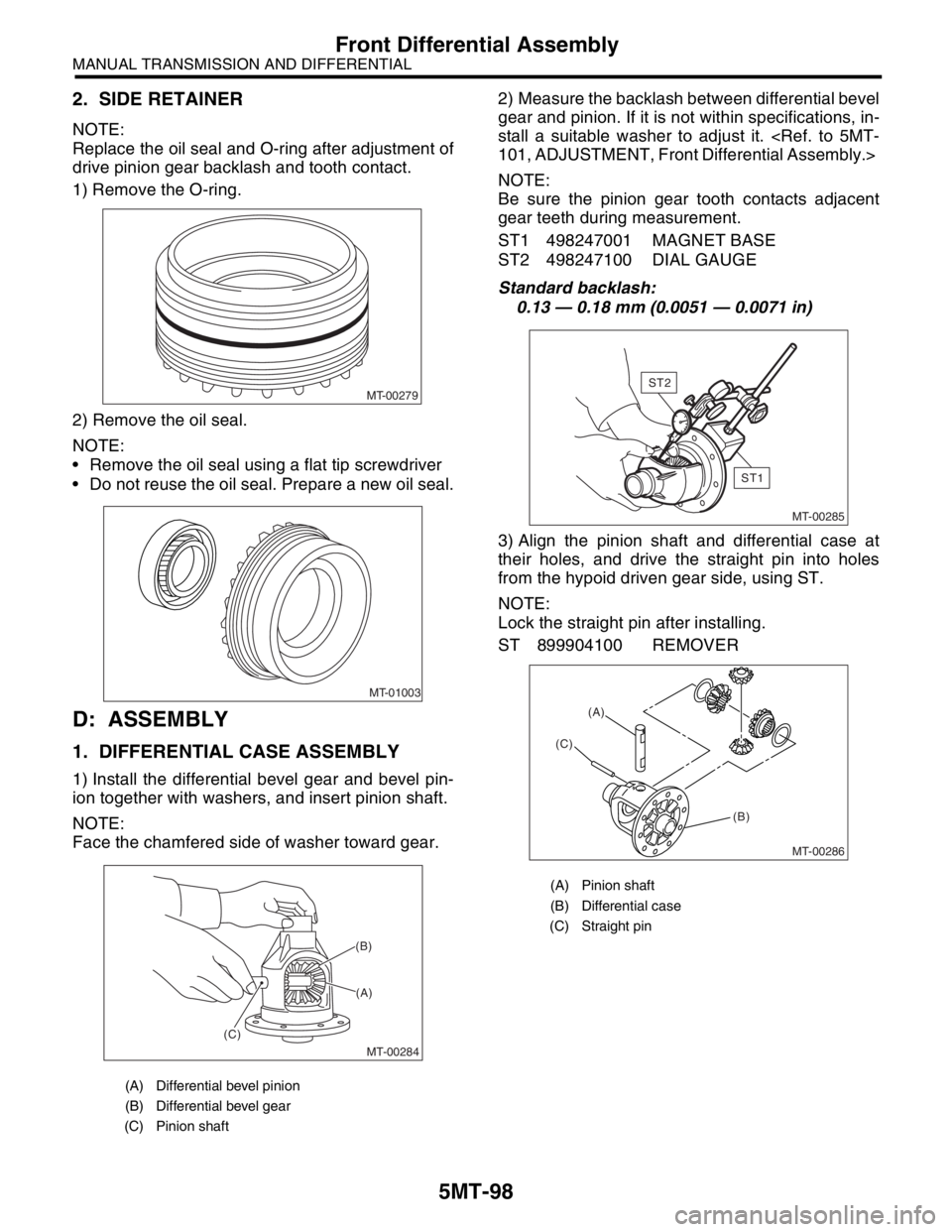
NOTE:
Replace the oil seal and O-ring after adjustment of
drive pinion gear backlash and tooth contact.
1) Remove the O-ring.
2) Remove the oil seal.
NOTE:
Remove the oil seal using a flat tip screwdriver
Do not reuse the oil seal. Prepare a new oil seal.
D: ASSEMBLY
1. DIFFERENTIAL CASE ASSEMBLY
1) Install the differential bevel gear and bevel pin-
ion together with washers, and insert pinion shaft.
NOTE:
Face the chamfered side of washer toward gear.2) Measure the backlash between differential bevel
gear and pinion. If it is not within specifications, in-
stall a suitable washer to adjust it.
NOTE:
Be sure the pinion gear tooth contacts adjacent
gear teeth during measurement.
ST1 498247001 MAGNET BASE
ST2 498247100 DIAL GAUGE
Standard backlash:
0.13 — 0.18 mm (0.0051 — 0.0071 in)
3) Align the pinion shaft and differential case at
their holes, and drive the straight pin into holes
from the hypoid driven gear side, using ST.
NOTE:
Lock the straight pin after installing.
ST 899904100 REMOVER
(A) Differential bevel pinion
(B) Differential bevel gear
(C) Pinion shaft
MT-00279
MT-01003
MT-00284
(A) (B)
(C)
(A) Pinion shaft
(B) Differential case
(C) Straight pin
MT-00285
ST1
ST2
MT-00286
(A)
(C)
(B)
Page 2846 of 2870
CL-20
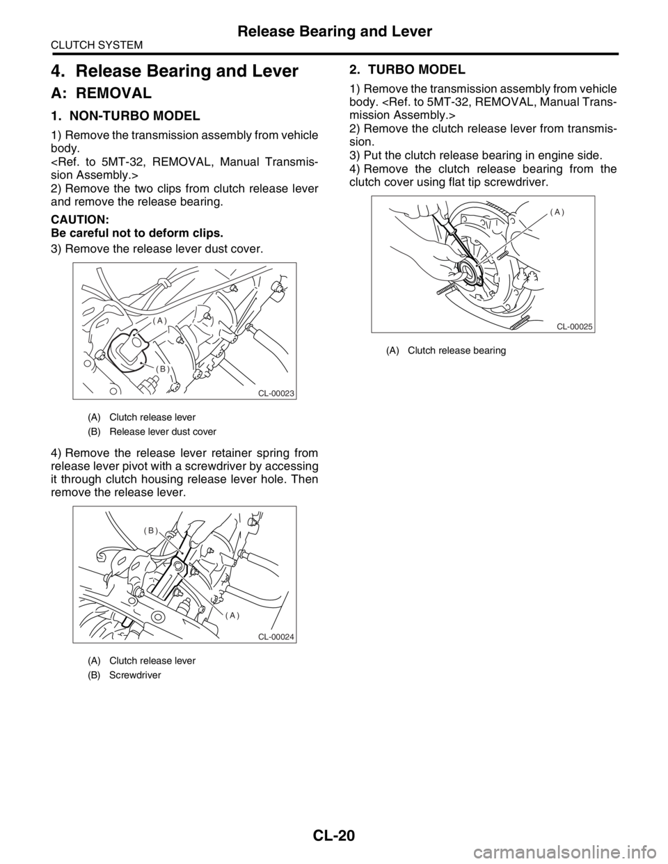
CLUTCH SYSTEM
Release Bearing and Lever
4. Release Bearing and Lever
A: REMOVAL
1. NON-TURBO MODEL
1) Remove the transmission assembly from vehicle
body.
2) Remove the two clips from clutch release lever
and remove the release bearing.
CAUTION:
Be careful not to deform clips.
3) Remove the release lever dust cover.
4) Remove the release lever retainer spring from
release lever pivot with a screwdriver by accessing
it through clutch housing release lever hole. Then
remove the release lever.
2. TURBO MODEL
1) Remove the transmission assembly from vehicle
body.
2) Remove the clutch release lever from transmis-
sion.
3) Put the clutch release bearing in engine side.
4) Remove the clutch release bearing from the
clutch cover using flat tip screwdriver.
(A) Clutch release lever
(B) Release lever dust cover
(A) Clutch release lever
(B) Screwdriver
CL-00023
(A)
(B)
CL-00024
(B)
(A)
(A) Clutch release bearing
CL-00025
(A)