battery SUBARU FORESTER 2004 Service Repair Manual
[x] Cancel search | Manufacturer: SUBARU, Model Year: 2004, Model line: FORESTER, Model: SUBARU FORESTER 2004Pages: 2870, PDF Size: 38.67 MB
Page 34 of 2870
AC-32
HVAC SYSTEM (HEATER, VENTILATOR AND A/C)
Blower Motor Unit Assembly
7. Blower Motor Unit Assembly
A: REMOVAL
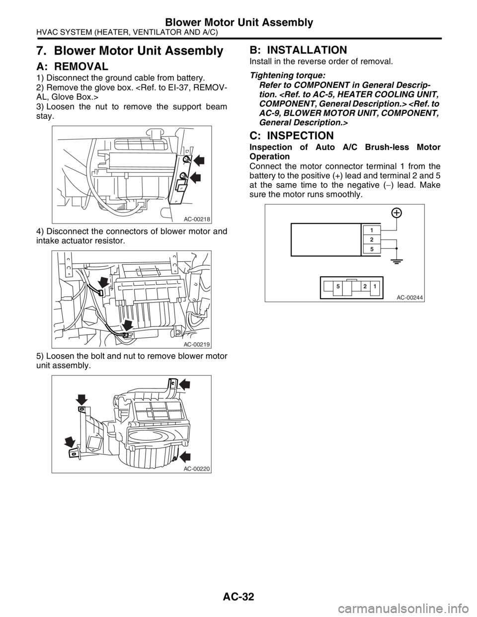
1) Disconnect the ground cable from battery.
2) Remove the glove box.
3) Loosen the nut to remove the support beam
stay.
4) Disconnect the connectors of blower motor and
intake actuator resistor.
5) Loosen the bolt and nut to remove blower motor
unit assembly.
B: INSTALLATION
Install in the reverse order of removal.
Tightening torque:
Refer to COMPONENT in General Descrip-
tion.
General Description.>
C: INSPECTION
Inspection of Auto A/C Brush-less Motor
Operation
Connect the motor connector terminal 1 from the
battery to the positive (+) lead and terminal 2 and 5
at the same time to the negative (−) lead. Make
sure the motor runs smoothly.
AC-00218
AC-00219
AC-00220
AC-00244
22
55
1 1
Page 37 of 2870
AC-35
HVAC SYSTEM (HEATER, VENTILATOR AND A/C)
Control Unit
10.Control Unit
A: REMOVAL
1) Disconnect the ground cable from battery.
2) In case of manual A/C, remove the mode cable
and air-mix cable from links of heater unit.
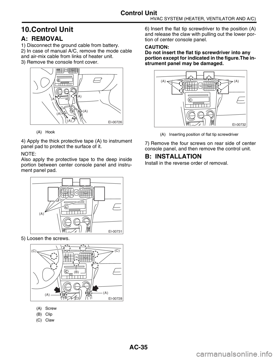
3) Remove the console front cover.
4) Apply the thick protective tape (A) to instrument
panel pad to protect the surface of it.
NOTE:
Also apply the protective tape to the deep inside
portion between center console panel and instru-
ment panel pad.
5) Loosen the screws.6) Insert the flat tip screwdriver to the position (A)
and release the claw with pulling out the lower por-
tion of center console panel.
CAUTION:
Do not insert the flat tip screwdriver into any
portion except for indicated in the figure.The in-
strument panel may be damaged.
7) Remove the four screws on rear side of center
console panel, and then remove the control unit.
B: INSTALLATION
Install in the reverse order of removal.
(A) Hook
(A) Screw
(B) Clip
(C) Claw
(A)
(A)
EI-00726
(A)
(A)
(A)
EI-00731
(A)
EI-00728
(C)
(A)(A)(C)
(B)
(A) Inserting position of flat tip screwdriver
EI-00732
(A) (A)
Page 38 of 2870
AC-36
HVAC SYSTEM (HEATER, VENTILATOR AND A/C)
Compressor
11.Compressor
A: INSPECTION
1. MAGNETIC CLUTCH CLEARANCE
1) Check the clearance of the entire circumference
around the drive plate and pulley.
Standard:
0.3 — 0.6 mm (0.0118 — 0.0236 in)
2. MAGNETIC CLUTCH OPERATION
1) Disconnect the compressor connector.
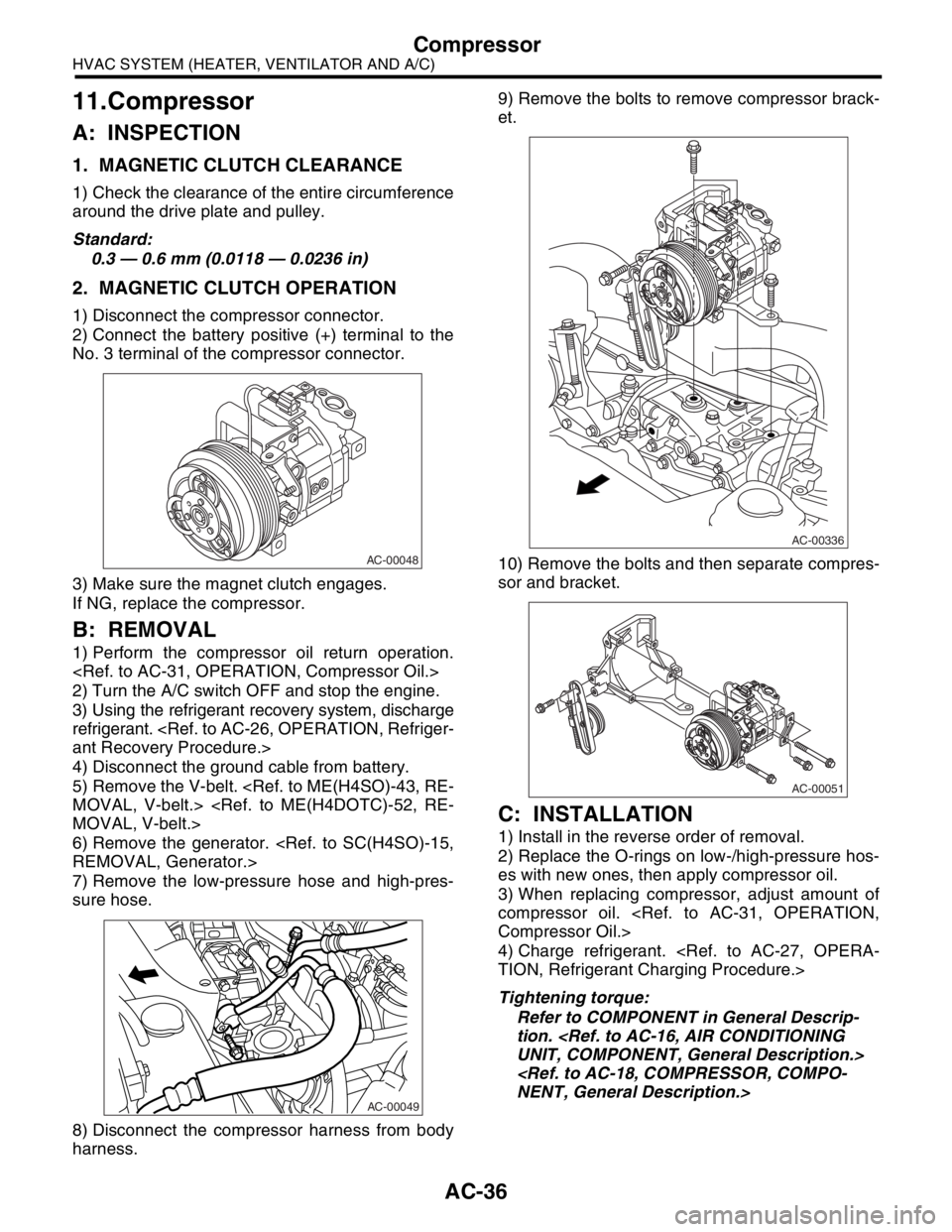
2) Connect the battery positive (+) terminal to the
No. 3 terminal of the compressor connector.
3) Make sure the magnet clutch engages.
If NG, replace the compressor.
B: REMOVAL
1) Perform the compressor oil return operation.
2) Turn the A/C switch OFF and stop the engine.
3) Using the refrigerant recovery system, discharge
refrigerant.
4) Disconnect the ground cable from battery.
5) Remove the V-belt.
6) Remove the generator.
7) Remove the low-pressure hose and high-pres-
sure hose.
8) Disconnect the compressor harness from body
harness.9) Remove the bolts to remove compressor brack-
et.
10) Remove the bolts and then separate compres-
sor and bracket.
C: INSTALLATION
1) Install in the reverse order of removal.
2) Replace the O-rings on low-/high-pressure hos-
es with new ones, then apply compressor oil.
3) When replacing compressor, adjust amount of
compressor oil.
4) Charge refrigerant.
Tightening torque:
Refer to COMPONENT in General Descrip-
tion.
AC-00048
AC-00049
AC-00336
AC-00051
Page 39 of 2870
AC-37
HVAC SYSTEM (HEATER, VENTILATOR AND A/C)
Condenser
12.Condenser
A: REMOVAL
1) Using the refrigerant recovery system, discharge
refrigerant.
2) Disconnect the ground cable from battery.
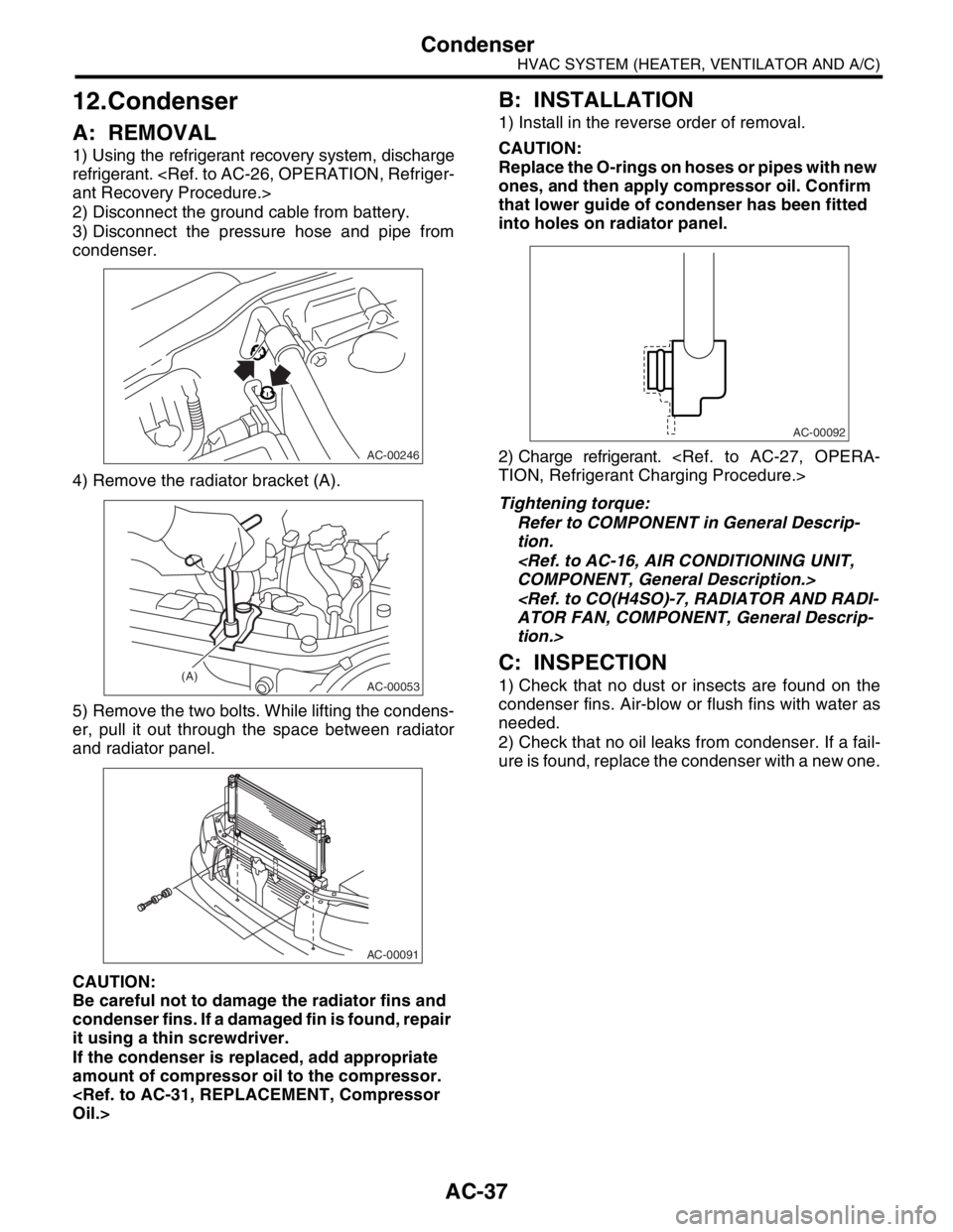
3) Disconnect the pressure hose and pipe from
condenser.
4) Remove the radiator bracket (A).
5) Remove the two bolts. While lifting the condens-
er, pull it out through the space between radiator
and radiator panel.
CAUTION:
Be careful not to damage the radiator fins and
condenser fins. If a damaged fin is found, repair
it using a thin screwdriver.
If the condenser is replaced, add appropriate
amount of compressor oil to the compressor.
B: INSTALLATION
1) Install in the reverse order of removal.
CAUTION:
Replace the O-rings on hoses or pipes with new
ones, and then apply compressor oil. Confirm
that lower guide of condenser has been fitted
into holes on radiator panel.
2) Charge refrigerant.
Tightening torque:
Refer to COMPONENT in General Descrip-
tion.
tion.>
C: INSPECTION
1) Check that no dust or insects are found on the
condenser fins. Air-blow or flush fins with water as
needed.
2) Check that no oil leaks from condenser. If a fail-
ure is found, replace the condenser with a new one.
AC-00246
AC-00053(A)
AC-00091
AC-00092
Page 41 of 2870
AC-39
HVAC SYSTEM (HEATER, VENTILATOR AND A/C)
Heater Cooling Unit
14.Heater Cooling Unit
A: REMOVAL
1) Disconnect the ground cable from battery.
2) Using the refrigerant recovery system, dis-
charge refrigerant.
3) Drain the engine coolant from radiator.
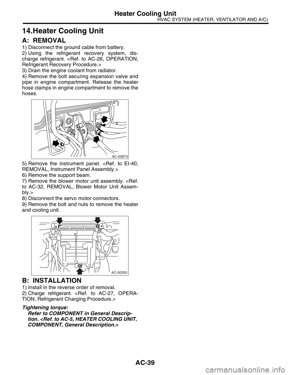
4) Remove the bolt securing expansion valve and
pipe in engine compartment. Release the heater
hose clamps in engine compartment to remove the
hoses.
5) Remove the instrument panel.
6) Remove the support beam.
7) Remove the blower motor unit assembly.
bly.>
8) Disconnect the servo motor connectors.
9) Remove the bolt and nuts to remove the heater
and cooling unit.
B: INSTALLATION
1) Install in the reverse order of removal.
2) Charge refrigerant.
Tightening torque:
Refer to COMPONENT in General Descrip-
tion.
AC-00870
AC-00055
Page 43 of 2870
AC-41
HVAC SYSTEM (HEATER, VENTILATOR AND A/C)
Hose and Tube
16.Hose and Tube
A: REMOVAL
CAUTION:
When disconnecting/connecting hoses, do not
apply excessive force to them. Confirm that no
torsion and excessive tension exists after install-
ing.
Seal the disconnected hose with a plug or vi-
nyl tape to prevent foreign matters from enter-
ing.
1) Disconnect the ground cable from battery.
2) Using the refrigerant recovery system, dis-
charge refrigerant.
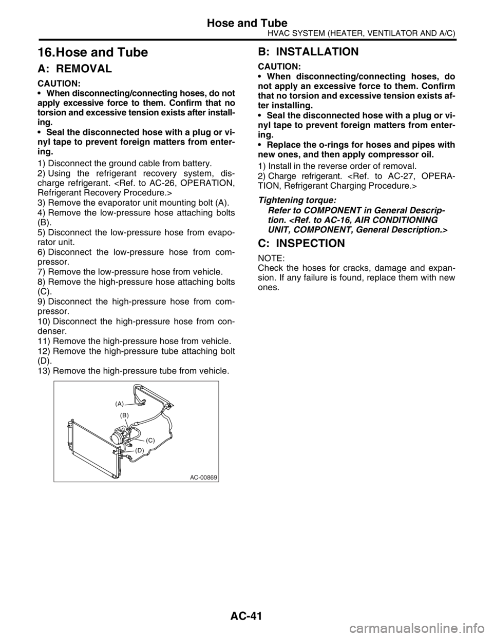
3) Remove the evaporator unit mounting bolt (A).
4) Remove the low-pressure hose attaching bolts
(B).
5) Disconnect the low-pressure hose from evapo-
rator unit.
6) Disconnect the low-pressure hose from com-
pressor.
7) Remove the low-pressure hose from vehicle.
8) Remove the high-pressure hose attaching bolts
(C).
9) Disconnect the high-pressure hose from com-
pressor.
10) Disconnect the high-pressure hose from con-
denser.
11) Remove the high-pressure hose from vehicle.
12) Remove the high-pressure tube attaching bolt
(D).
13) Remove the high-pressure tube from vehicle.
B: INSTALLATION
CAUTION:
When disconnecting/connecting hoses, do
not apply an excessive force to them. Confirm
that no torsion and excessive tension exists af-
ter installing.
Seal the disconnected hose with a plug or vi-
nyl tape to prevent foreign matters from enter-
ing.
Replace the o-rings for hoses and pipes with
new ones, and then apply compressor oil.
1) Install in the reverse order of removal.
2) Charge refrigerant.
Tightening torque:
Refer to COMPONENT in General Descrip-
tion.
C: INSPECTION
NOTE:
Check the hoses for cracks, damage and expan-
sion. If any failure is found, replace them with new
ones.
AC-00869
(A)
(C) (B)
(D)
Page 44 of 2870
AC-42
HVAC SYSTEM (HEATER, VENTILATOR AND A/C)
Relay and Fuse
17.Relay and Fuse
A: LOCATIONB: INSPECTION
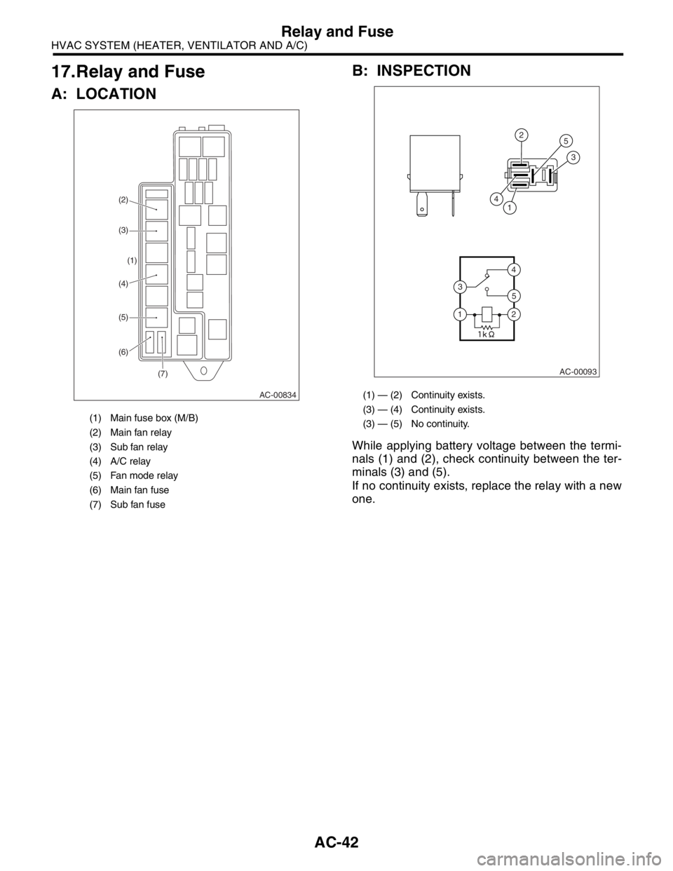
While applying battery voltage between the termi-
nals (1) and (2), check continuity between the ter-
minals (3) and (5).
If no continuity exists, replace the relay with a new
one.
(1) Main fuse box (M/B)
(2) Main fan relay
(3) Sub fan relay
(4) A/C relay
(5) Fan mode relay
(6) Main fan fuse
(7) Sub fan fuse
AC-00834
(7) (6) (5) (4)(1) (3) (2)
(1) — (2) Continuity exists.
(3) — (4) Continuity exists.
(3) — (5) No continuity.
AC-00093
4
4
5
2
25
3
3
1
1
Page 46 of 2870
AC-44
HVAC SYSTEM (HEATER, VENTILATOR AND A/C)
Ambient Sensor (Auto A/C Model)
19.Ambient Sensor (Auto A/C
Model)
A: REMOVAL
1) Open the front hood.
2) Disconnect the ground cable from battery.
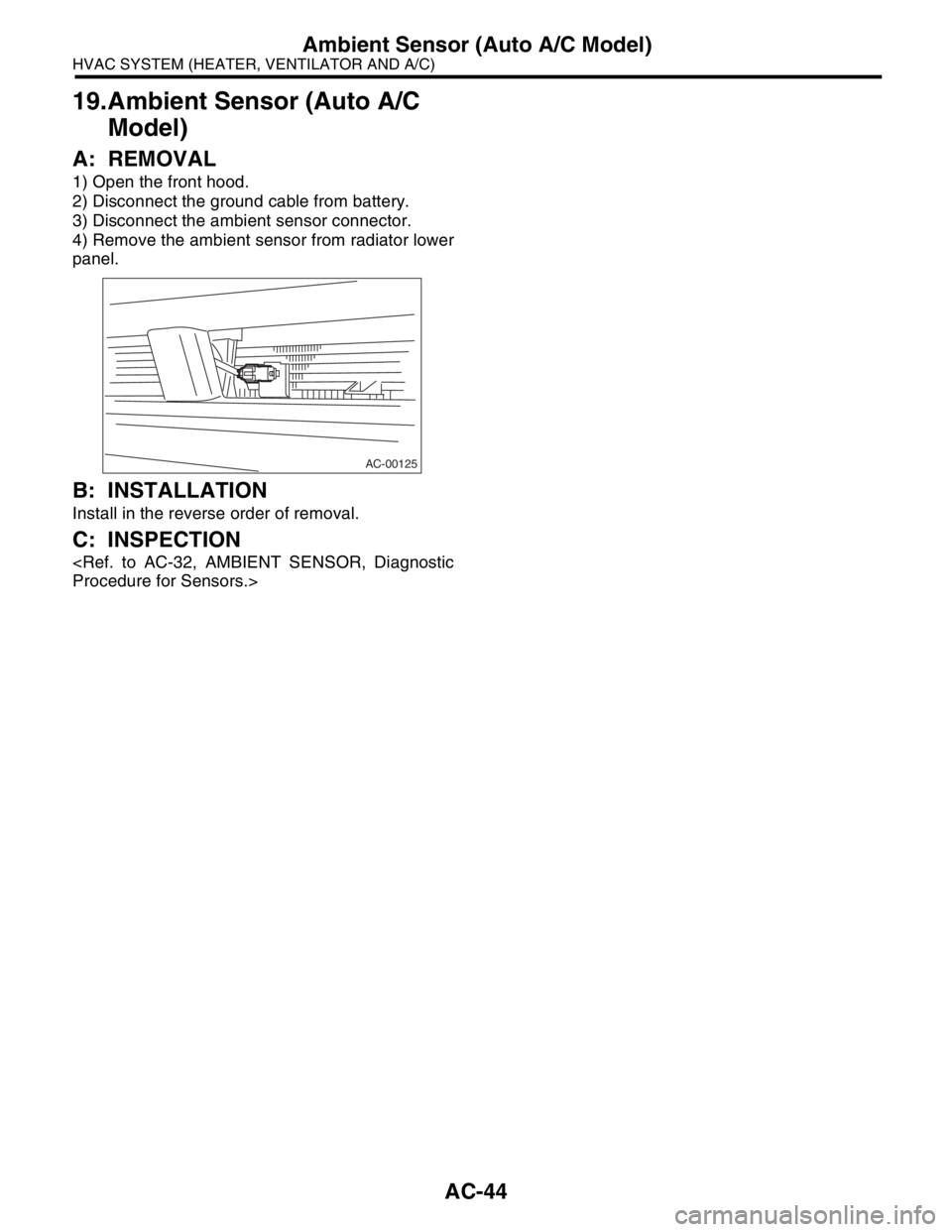
3) Disconnect the ambient sensor connector.
4) Remove the ambient sensor from radiator lower
panel.
B: INSTALLATION
Install in the reverse order of removal.
C: INSPECTION
AC-00125
Page 47 of 2870

AC-45
HVAC SYSTEM (HEATER, VENTILATOR AND A/C)
Sunload Sensor (Auto A/C Model)
20.Sunload Sensor (Auto A/C
Model)
A: REMOVAL
1) Disconnect the ground cable from battery.
2) Disconnect the sunload sensor connector.
CAUTION:
Be careful not to damage the sensors and inte-
rior trims when removing them.
B: INSTALLATION
Install in the reverse order of removal.
C: INSPECTION
AC-00126
Page 48 of 2870
AC-46
HVAC SYSTEM (HEATER, VENTILATOR AND A/C)
Air Vent Grille
21.Air Vent Grille
A: REMOVAL
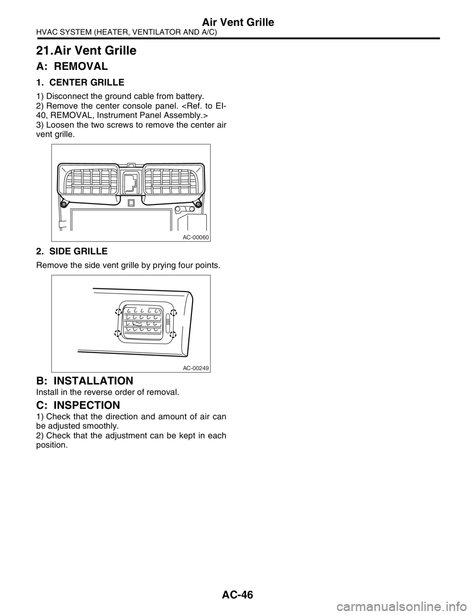
1. CENTER GRILLE
1) Disconnect the ground cable from battery.
2) Remove the center console panel.
3) Loosen the two screws to remove the center air
vent grille.
2. SIDE GRILLE
Remove the side vent grille by prying four points.
B: INSTALLATION
Install in the reverse order of removal.
C: INSPECTION
1) Check that the direction and amount of air can
be adjusted smoothly.
2) Check that the adjustment can be kept in each
position.
AC-00060
AC-00249