relay SUBARU FORESTER 2004 Service User Guide
[x] Cancel search | Manufacturer: SUBARU, Model Year: 2004, Model line: FORESTER, Model: SUBARU FORESTER 2004Pages: 2870, PDF Size: 38.67 MB
Page 97 of 2870

AC-41
HVAC SYSTEM (AUTO A/C)(DIAGNOSTIC)
General Diagnostic Table
9. General Diagnostic Table
A: INSPECTION
Symptom Problem parts
A/C system fails to operate.Fuse
Connector (Poor contact)
Ground
Auto A/C control module
Blower fan motor
Blower fan relay
A/C Relay
Compressor (Magnet clutch)
Evaporator sensor
Fuse is blown out.Fuse
Connector (Poor contact)
Illumination cannot dim.Fuse
Connector (Poor contact)
Auto A/C control module
Blower fan does not rotate or fan speed cannot be controlled.Fuse
Connector (Poor contact)
Ground
Auto A/C control module
Blower fan motor
Blower fan relay
Unable to switch suction vents. Connector (Poor contact)
Auto A/C control module
Intake door actuator
Unable to switch blow vents. Connector (Poor contact)
Auto A/C control module
Mode door actuator
Compartment temperature does not increase. (No hot air is dis-
charged.) Connector (Poor contact)
Auto A/C control module
Air mix door actuator
In-vehicle sensor, ambient sensor, evaporator sensor and
sunload sensor
In-vehicle sensor aspirator hose
Compartment temperature does not decrease. (No cool air is
discharged.) Connector (Poor contact)
Auto A/C control module
Air mix door actuator
A/C Relay
Compressor (Magnet clutch)
Radiator fan motor
Radiator fan relay
In-vehicle sensor, ambient sensor, evaporator sensor and
sunload sensor
In-vehicle sensor aspirator hose
Compartment temperature is higher or lower than setting tem-
perature. Auto A/C control module
Air mix door actuator
In-vehicle sensor, ambient sensor, evaporator sensor and
sunload sensor
In-vehicle sensor aspirator hose
Compartment temperature does not quickly respond to setting
temperature. Air mix door actuator
In-vehicle sensor, ambient sensor, evaporator sensor and
sunload sensor
In-vehicle sensor aspirator hose
Radiator fan does not rotate during A/C operation. Radiator fan motor
Radiator fan relay
Page 153 of 2870

AB-21
AIRBAG SYSTEM (DIAGNOSTIC)
Airbag Control Module I/O Signal
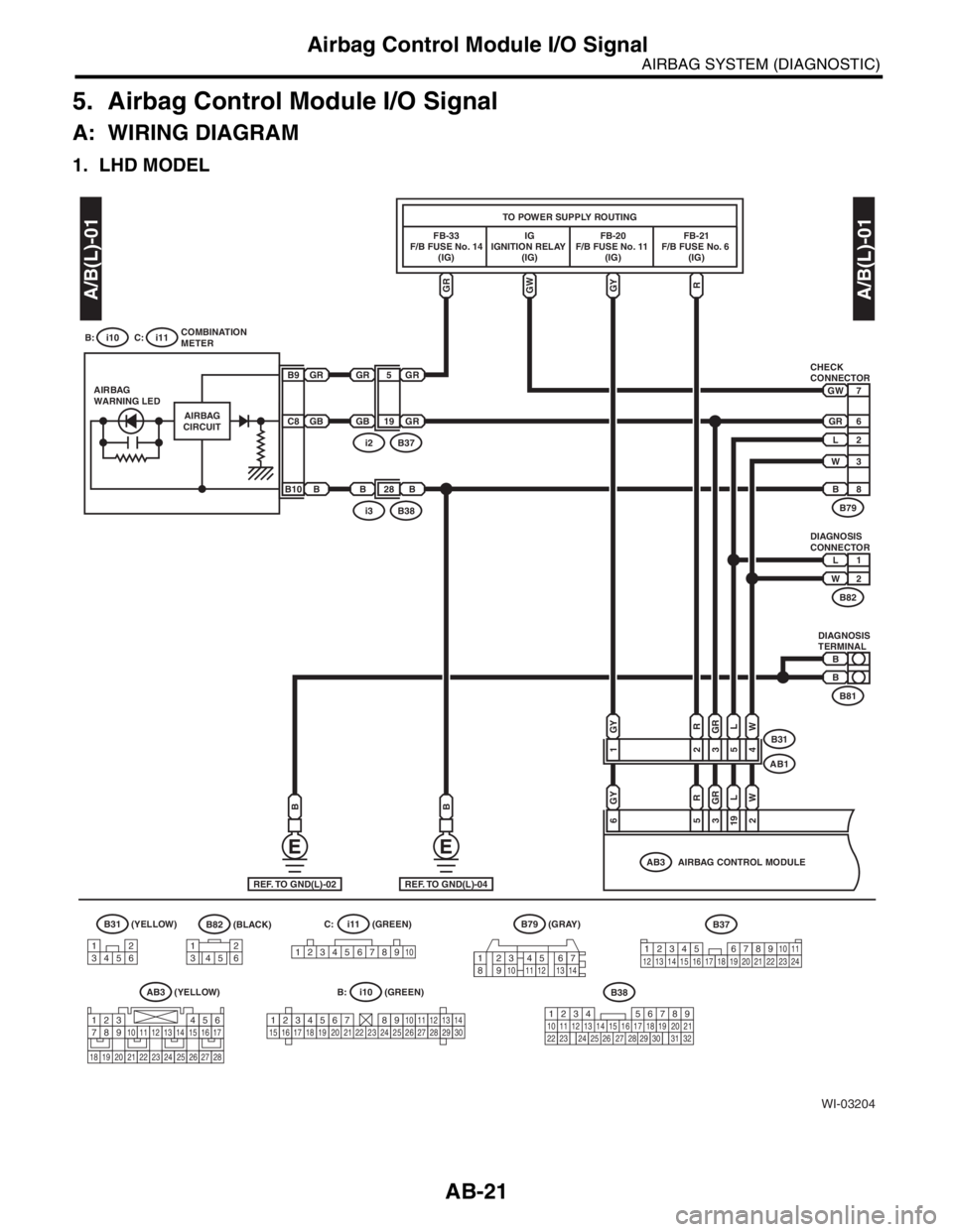
5. Airbag Control Module I/O Signal
A: WIRING DIAGRAM
1. LHD MODEL
B31(BLACK)(GREEN)
(GREEN) (YELLOW)
(YELLOW)B82
WI-03204
7
6
2
3
8
GWGRGY
GY
R
GRGB
GRL
W
GYRGRLW
19
BB28
1
R
2354
653192
AIRBAG
CIRCUIT AIRBAG
WARNING LED
IG
IGNITION RELAY
(IG) FB-33
F/B FUSE No. 14
(IG)FB-20
F/B FUSE No. 11
(IG)FB-21
F/B FUSE No. 6
(IG)
L
GR
GW
W
B
GRGR5GR
GB
B9
C8
BB10
1
2
L
W
REF. TO GND(L)-04
CHECK
CONNECTOR
DIAGNOSIS
CONNECTOR
DIAGNOSIS
TERMINAL
B31
AB1
AIRBAG CONTROL MODULE
AB3
B81
B82
B79B38i3
B37i2
TO POWER SUPPLY ROUTING
(GRAY)
B79
1234567891011121314
B
B
12
3456
B37
AB3
COMBINATION
METER B: C:
i11i10
i11
i10 B: C:
A/B(L)-01
A/B(L)-01
12345678910
123456789101112131415161718192021222324252627282930
34 128910 11
12 13 14 15 16 17 18 19 20 21 22 23 24567
1234567891011121314151617
1819202122232425262728
1
34562
B38
219
32
1234 5610 11 12 13 14 15716
23 3019 20
22 26 27 28 29817
24 3118
25
REF. TO GND(L)-02
BB
Page 156 of 2870

AB-24
AIRBAG SYSTEM (DIAGNOSTIC)
Airbag Control Module I/O Signal
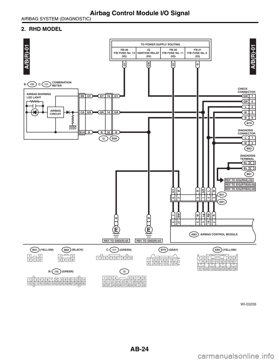
2. RHD MODEL
A/B(R)-01A/B(R)-01
WI-03206
7
6
2
3
8
GWGY
GY
R
GRGR
RGRL
W
YWLgRBR
10
BB20
65143
6
B
BW
2
2753192
IG
IGNITION RELAY
(IG)FB-36
F/B FUSE No. 14
(IG)FB-20
F/B FUSE No. 11
(IG)FB-21
F/B FUSE No. 6
(IG)
L
GR
GW
W
B
GYGY16GY
GR
B
B9
C8
B10
1
2
L
W
BL
BL
REF. TO GND(R)-04
REF. TO E/G(RNA)-05REF. TO E/G(RTB20)-05REF. TO E/G(RTB25)-05
CHECK
CONNECTOR
DIAGNOSIS
CONNECTOR
DIAGNOSIS
TERMINAL
B31
AB1
(GRAY)
B79
AIRBAG CONTROL MODULE
AB3
B81
B82
B79
B38i3
TO POWER SUPPLY ROUTING
1234567891011121314
GY
(BLACK)B82
B
REF. TO GND(R)-05
B
i3
B31(GREEN) i11 C:
B:
(GREEN)
i10
AIRBAG
CIRCUIT AIRBAG WARNING
LED LIGHT
COMBINATION
METER B: C:
i11i10
12
34561
3456212345678910
123456789101112131415161718192021222324252627282930
(YELLOW)
AB3
1234567891011121314151617
1819202122232425262728
(YELLOW)
219
32
1234
5610 11 12 13 14 15716
23 3019 20
22 26 27 28 29817
24 3118
25
Page 172 of 2870

AB-40
AIRBAG SYSTEM (DIAGNOSTIC)
Airbag Warning Light Failure
Step Check Yes No
1 CHECK COMBINATION METER.
Turn the ignition switch to ON, and confirm that
warning lights equipped in the combination
meter are turned on.Do the warning lights not for
airbag turn on?Go to step 2.Repair the combi-
nation meter
power supply.
Meter System.>
2 CHECK FUSE NO. 14 (IN FUSE&RELAY
BOX).
Remove the fuse No. 14 and perform visual
inspection.Is the fuse No. 14 (in fuse &
relay box) blown out? Replace the fuse
No. 14. If fuse No.
14 blows again, go
to step 3. Go to step 3.
3 CHECK AIRBAG WARNING LIGHT CIRCUIT
(IN COMBINATION METER).
1) Turn the ignition switch to OFF, disconnect
the battery ground cable, and wait more than
20 seconds.
2) Disconnect the connector (AB1) from
(B31).
3) Connect the battery ground cable and turn
the ignition switch to ON.Is the airbag warning light
turned on?Go to step 4.Replace the airbag
warning light bulb
or combination
meter printed cir-
cuit.
Meter Assembly.>
4 CHECK AIRBAG MAIN HARNESS.
1) Turn the ignition switch to OFF, disconnect
the battery ground cable, and wait more than
20 seconds.
2) Connect the connector (AB1) to (B31).
3) Disconnect the connector (AB3) from the
airbag control module.
4) Connect the battery ground cable and turn
the ignition switch to ON.Is the airbag warning light
turned on?Replace the airbag
control module.
Module.>Replace the airbag
main harness with
body harness.
Page 174 of 2870

AB-42
AIRBAG SYSTEM (DIAGNOSTIC)
Airbag Warning Light Failure
Step Check Yes No
1 CHECK COMBINATION METER.
Turn the ignition switch to ON, and confirm that
warning lights equipped in the combination
meter are turned on.Do the warning lights not for
airbag turn on?Go to step 2.Repair the combi-
nation meter
power supply.
Meter System.>
2 CHECK FUSE NO. 14 (IN FUSE&RELAY
BOX).
Remove the fuse No. 14 and perform visual
inspection.Is the fuse No. 14 (in fuse &
relay box) blown out?Replace the fuse
No. 14. If fuse No.
14 blows again, go
to step 3. Go to step 3.
3 CHECK AIRBAG WARNING LIGHT CIRCUIT
(IN COMBINATION METER).
1) Turn the ignition switch to OFF, disconnect
the battery ground cable, and wait more than
20 seconds.
2) Disconnect the connector (AB1) from
(B31).
3) Connect the battery ground cable and turn
the ignition switch to ON.Is the airbag warning light
turned on?Go to step 4.Replace the airbag
warning light bulb
or combination
meter printed cir-
cuit.
Meter Assembly.>
4 CHECK AIRBAG MAIN HARNESS.
1) Turn the ignition switch to OFF, disconnect
the battery ground cable, and wait more than
20 seconds.
2) Connect the connector (AB1) to (B31).
3) Disconnect the connector (AB3) from the
airbag control module.
4) Connect the battery ground cable and turn
the ignition switch to ON.Is the airbag warning light
turned on?Replace the airbag
control module.
Module.>Replace the airbag
main harness with
body harness.
Page 190 of 2870

AB-58
AIRBAG SYSTEM (DIAGNOSTIC)
Diagnostic Procedure with Diagnostic Trouble Code (DTC)
H: DTC 24
DIAGNOSIS:
Airbag control module is faulty.
Airbag main harness circuit is open.
Fuse No. 11 (in fuse and relay box) is blown.
Body harness circuit is open.
CAUTION:
Before diagnosing the airbag system, be sure to turn the ignition switch to OFF, disconnect the
ground cable from battery, and wait more than 20 seconds before starting to work.
After replacing the airbag module, seat belt pretensioner, roll connector, control module or sensor,
reconnect each part and confirm that the airbag warning light operates properly.
When inspecting the airbag main harness, disconnect the driver’s airbag module and passenger’s
airbag module connectors for safety reasons.
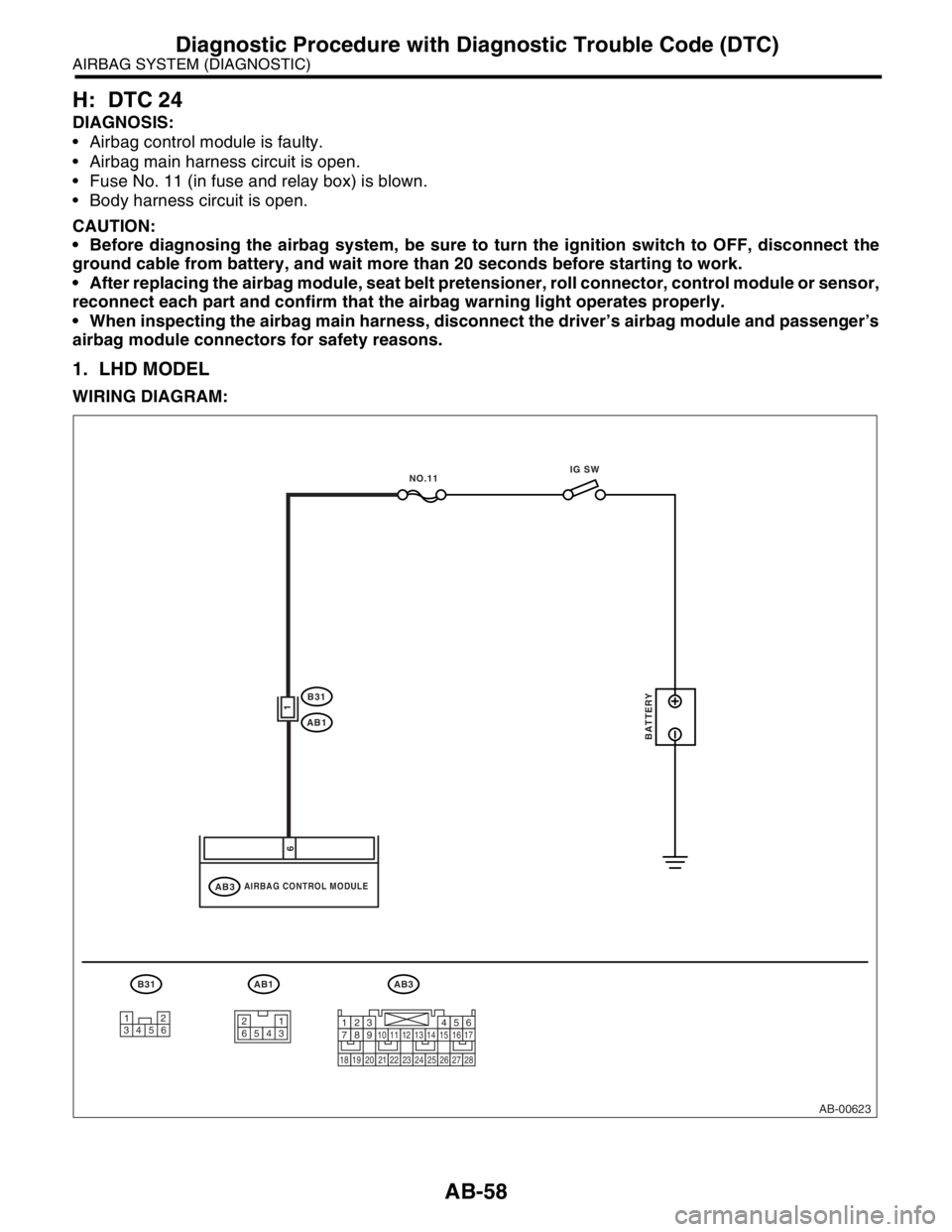
1. LHD MODEL
WIRING DIAGRAM:
AB-00623
AB3
AIRBAG CONTROL MODULEAB3
B31
AB1
AB1
1
6
BATTERY
IG SW
NO.11
B31
12
34561
23 45 61234567891011121314151617
1819202122232425262728
Page 191 of 2870

AB-59
AIRBAG SYSTEM (DIAGNOSTIC)
Diagnostic Procedure with Diagnostic Trouble Code (DTC)
Step Check Yes No
1 CHECK AIRBAG CONTROL MODULE.
1) Turn the ignition switch to OFF, disconnect
the battery ground cable, and wait more than
20 seconds.
2) Disconnect the connector (AB3) from the
airbag control module.
3) Connect the connector (1R) in test harness
R to connector (AB3).
4) Connect the battery ground cable and turn
the ignition switch to ON.
5) Measure the voltage between connector
(2R) in test harness R and chassis ground.
Connector & terminal
(2R) No. 1 (+) — Chassis ground (
−): Is the voltage more than 10 V? Replace the airbag
control module.
Module.>Go to step 2.
2 CHECK AIRBAG MAIN HARNESS.
1) Turn the ignition switch to OFF, disconnect
the battery ground cable, and wait more than
20 seconds.
2) Disconnect the airbag connector (AB1)
from the body harness (B31).
3) Connect the connector (2M) in test harness
M to connector (AB1).
4) Measure the resistance between connector
(5M) in test harness M and the connector (2R)
in test harness R.
Connector & terminal
(5M) No. 2 — (2R) No. 1: Is the resistance less than 10
Ω?Go to step 3.Replace the airbag
main harness with
body harness.
3 CHECK AIRBAG MAIN HARNESS.
Measure the following resistance with the
above-mentioned condition maintained.
Connector & terminal
(5M) No. 2 — Chassis ground:
(2R) No. 1 — Chassis ground:Is the resistance more than 1
MΩ?Go to step 4.Replace the airbag
main harness with
body harness.
4 CHECK FUSE No. 11 (IN JOINT BOX).
1) Confirm that the ignition switch is turned
OFF.
2) Remove the fuse No. 11 (in fuse and relay
box) and perform visual inspection.Is the fuse No. 11 blown out? Replace the fuse
No. 11. If fuse No.
11 blows out
again, repair the
body harness. Repair the body
harness.
Page 193 of 2870

AB-61
AIRBAG SYSTEM (DIAGNOSTIC)
Diagnostic Procedure with Diagnostic Trouble Code (DTC)
Step Check Yes No
1 CHECK AIRBAG CONTROL MODULE.
1) Turn the ignition switch to OFF, disconnect
the battery ground cable, and wait more than
20 seconds.
2) Disconnect the connector (AB3) from the
airbag control module.
3) Connect the connector (1R) in test harness
R to connector (AB3).
4) Connect the battery ground cable and turn
the ignition switch to ON.
5) Measure the voltage between connector
(2R) in test harness R and chassis ground.
Connector & terminal
(2R) No. 1 (+) — Chassis ground (
−): Is the voltage more than 10 V? Replace the airbag
control module.
Module.>Go to step 2.
2 CHECK AIRBAG MAIN HARNESS.
1) Turn the ignition switch to OFF, disconnect
the battery ground cable, and wait more than
20 seconds.
2) Disconnect the airbag connector (AB1)
from the body harness (B31).
3) Connect the connector (2M) in test harness
M to connector (AB1).
4) Measure the resistance between connector
(5M) in test harness M and the connector (2R)
in test harness R.
Connector & terminal
(5M) No. 9 — (2R) No. 1: Is the resistance less than 10
Ω?Go to step 3.Replace the airbag
main harness with
body harness.
3 CHECK AIRBAG MAIN HARNESS.
Measure the following resistance with the
above-mentioned condition maintained.
Connector & terminal
(5M) No. 9 — Chassis ground:
(2R) No. 1 — Chassis ground: Is the resistance more than 1
MΩ? Go to step 4.Replace the airbag
main harness with
body harness.
4 CHECK FUSE No. 11 (IN FUSE AND RELAY
BOX).
1) Confirm that the ignition switch is turned
OFF.
2) Remove the fuse No. 11 (in fuse and relay
box) and perform visual inspection.Fuse No. 11 is not blown out. Replace the fuse
No. 11. If fuse No.
11 blows out
again, repair the
body harness. Repair the body
harness.
Page 195 of 2870

AB-63
AIRBAG SYSTEM (DIAGNOSTIC)
Diagnostic Procedure with Diagnostic Trouble Code (DTC)
Step Check Yes No
1 CHECK AIRBAG CONTROL MODULE.
1) Turn the ignition switch to OFF, disconnect
the battery ground cable, and wait more than
20 seconds.
2) Disconnect the connector (AB3) from air-
bag control module.
3) Connect the connector (1R) in test harness
R to connector (AB3).
4) Connect the battery ground cable, and turn
the ignition switch to ON.
5) Measure the voltage between the connec-
tor (2R) in test harness R and the chassis
ground.
Connector & terminal
(2R) No. 6 (+) — Chassis ground (
−): Is the voltage more than 10 V? Replace the airbag
control module.
Module.>Go to step 2.
2 CHECK AIRBAG MAIN HARNESS.
1) Turn the ignition switch to OFF, disconnect
the battery ground cable, and wait more than
20 seconds.
2) Disconnect the airbag connector (AB1)
from the body harness (B31).
3) Connect the connector (2M) in test harness
M to the airbag connector (AB1).
4) Measure the resistance between the con-
nector (5M) in test harness M and the connec-
tor (2R) in test harness R.
Connector & terminal
(5M) No. 4 — (2R) No. 6: Is the resistance less than 10
Ω?Go to step 3.Replace the airbag
main harness with
body harness.
3 CHECK AIRBAG MAIN HARNESS.
Measure the following resistance with the
above-mentioned condition maintained.
Connector & terminal
(5M) No. 4 — Chassis ground:
(2R) No. 6 — Chassis ground: Is the resistance more than 1
MΩ?Go to step 4.Replace the airbag
main harness with
body harness.
4 CHECK FUSE NO. 6 (IN FUSE AND RELAY
BOX).
1) Confirm that the ignition switch is turned
OFF.
2) Remove the No. 6 fuse (in fuse and relay
box) and perform visual inspection.Is the fuse No. 6 blown out? Replace the fuse
No. 6. If fuse No. 6
is blown out again,
repair the body
harness. Repair the body
harness.
Page 197 of 2870

AB-65
AIRBAG SYSTEM (DIAGNOSTIC)
Diagnostic Procedure with Diagnostic Trouble Code (DTC)
Step Check Yes No
1 CHECK AIRBAG CONTROL MODULE.
1) Turn the ignition switch to OFF, disconnect
the battery ground cable, and wait more than
20 seconds.
2) Disconnect the connector (AB3) from air-
bag control module.
3) Connect the connector (1R) in test harness
R to connector (AB3).
4) Connect the battery ground cable, and turn
the ignition switch to ON.
5) Measure the voltage between the connec-
tor (2R) in test harness R and the chassis
ground.
Connector & terminal
(2R) No. 6 (+) — Chassis ground (
−): Is the voltage more than 10 V? Replace the airbag
control module.
Module.>Go to step 2.
2 CHECK AIRBAG MAIN HARNESS.
1) Turn the ignition switch to OFF, disconnect
the battery ground cable, and wait more than
20 seconds.
2) Disconnect the airbag connector (AB1)
from the body harness (B31).
3) Connect the connector (2M) in test harness
M to the airbag connector (AB1).
4) Measure the resistance between the con-
nector (5M) in test harness M and the connec-
tor (2R) in test harness R.
Connector & terminal
(5M) No. 4 — (2R) No. 6: Is the resistance less than 10
Ω?Go to step 3.Replace the airbag
main harness with
body harness.
3 CHECK AIRBAG MAIN HARNESS.
Measure the following resistance with the
above-mentioned condition maintained.
Connector & terminal
(5M) No. 1 — Chassis ground:
(2R) No. 6 — Chassis ground: Is the resistance more than 1
MΩ? Go to step 4.Replace the airbag
main harness with
body harness.
4 CHECK FUSE NO. 6 (IN FUSE AND RELAY
BOX).
1) Confirm that the ignition switch is turned
OFF.
2) Remove the No. 6 fuse (in fuse and relay
box) and perform visual inspection.Is the fuse No. 6 blown out? Replace the fuse
No. 6. If fuse No. 6
is blown out again,
repair the body
harness. Repair the body
harness.