open hood SUBARU FORESTER 2004 Service Repair Manual
[x] Cancel search | Manufacturer: SUBARU, Model Year: 2004, Model line: FORESTER, Model: SUBARU FORESTER 2004Pages: 2870, PDF Size: 38.67 MB
Page 27 of 2870

AC-25
HVAC SYSTEM (HEATER, VENTILATOR AND A/C)
Refrigerant Pressure with Manifold Gauge Set
2. Refrigerant Pressure with Manifold Gauge Set
A: OPERATION
1) Place the vehicle in the shade and draftless condition.
2) Connect the manifold gauge set.
3) Open the front windows and close all doors.
4) Open the hood.
5) Increase the engine speed to 1,500 rpm.
6) Turn ON the A/C switch.
7) Turn the temperature control dial to MAX COOL.
8) Set the air inlet select switch to RECIRC position.
9) Turn the fan dial to HI.
10) Read the gauge.
Standard:
Low pressure: 127 — 196 kPa (1.3 — 2.0 kg/cm
2, 18 — 28 psi)
High pressure: 1,471 — 1, 667 kPa (15 — 17 kg/cm2, 213 — 242 psi)
Ambient temperature: 30 — 35
°C (86 — 95°F)
B: INSPECTION
Symptom Probable cause Repair order
High-pressure side is unusually high. Defective condenser fan motor
Clogged condenser fin
Too much refrigerant
Air inside the system
Defective receiver dryer Replace the fan motor.
Clean the condenser fin.
Discharge refrigerant.
Replace the receiver dryer.
After reevacuating the receiver dryer,
charge appropriate amount of refriger-
ant.
High-pressure side is unusually low. Defective compressor
Not enough refrigerant
Clogged expansion valve
Expansion valve frozen temporarily by
moisture Replace the compressor.
Check for leaks.
Replace the expansion valve.
Fully evacuate the expansion valve.
Low-pressure side is unusually high. Defective compressor
Defective expansion valve
Too much refrigerant Replace the compressor.
Replace the expansion valve.
Discharge refrigerant.
Low-pressure side is unusually low. Not enough refrigerant
Clogged expansion valve
Expansion valve frozen temporarily by
moisture
Saturated receiver dryer Check for leaks.
Replace the expansion valve.
Replace the receiver dryer.
Page 46 of 2870
AC-44
HVAC SYSTEM (HEATER, VENTILATOR AND A/C)
Ambient Sensor (Auto A/C Model)
19.Ambient Sensor (Auto A/C
Model)
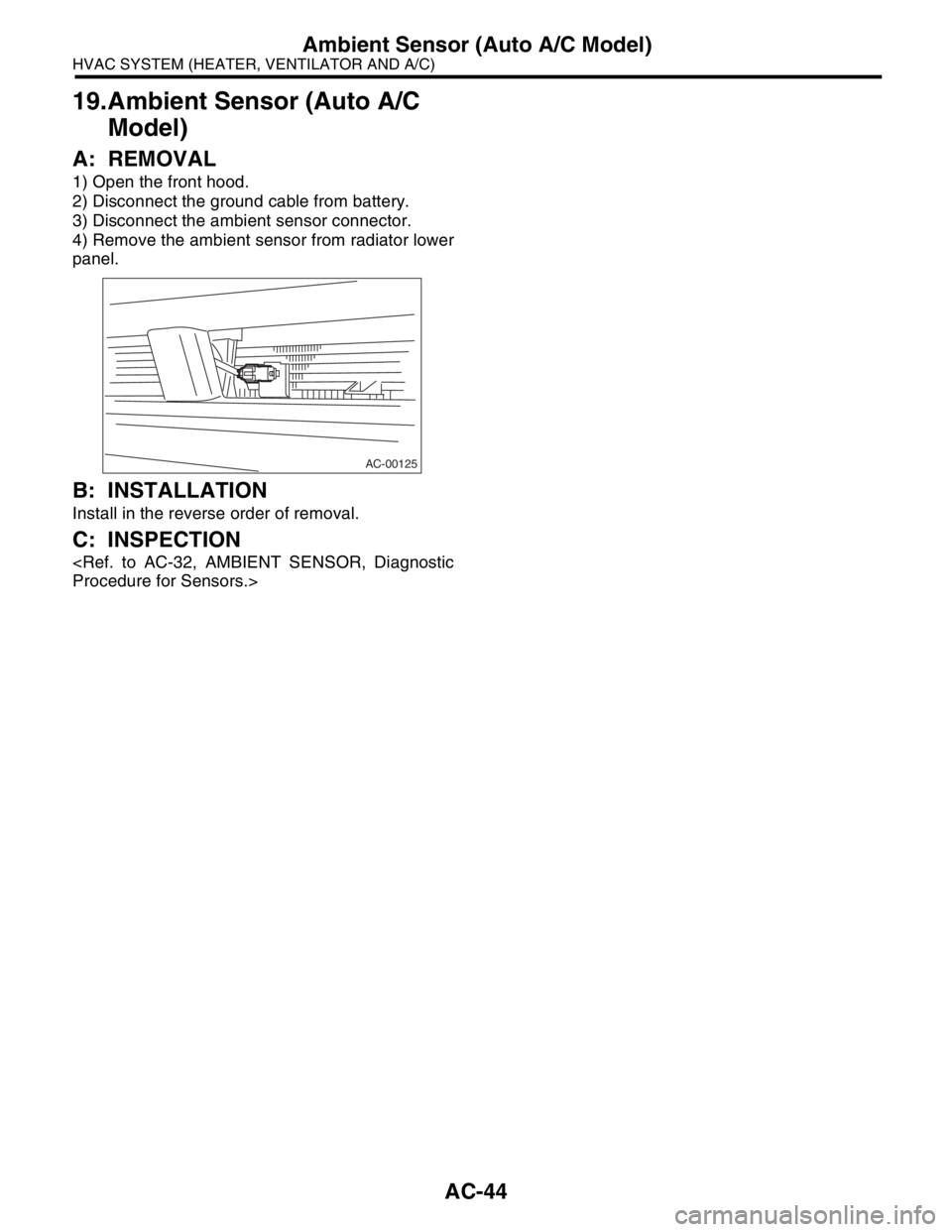
A: REMOVAL
1) Open the front hood.
2) Disconnect the ground cable from battery.
3) Disconnect the ambient sensor connector.
4) Remove the ambient sensor from radiator lower
panel.
B: INSTALLATION
Install in the reverse order of removal.
C: INSPECTION
AC-00125
Page 299 of 2870
WW-11
WIPER AND WASHER SYSTEM
Washer Tank and Motor
5. Washer Tank and Motor
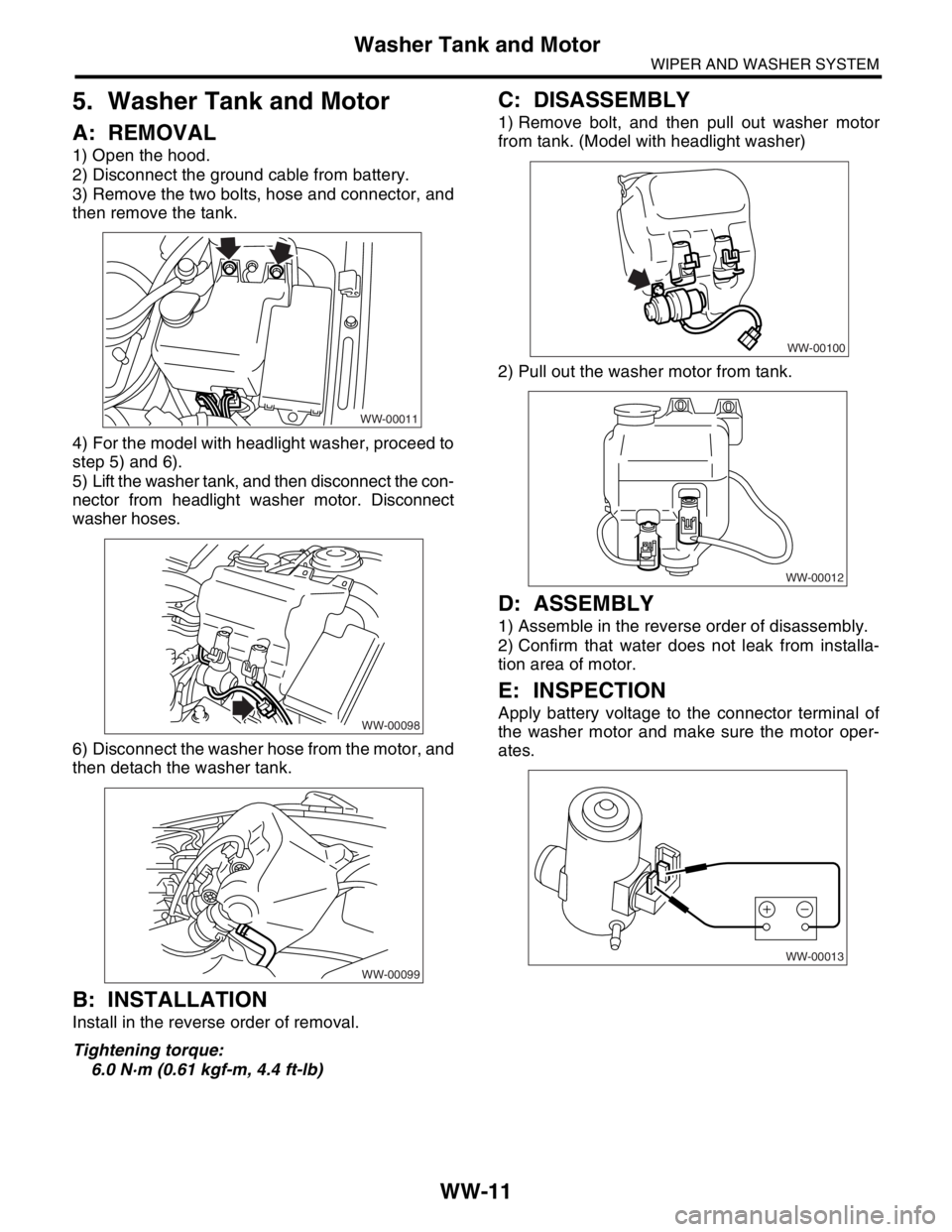
A: REMOVAL
1) Open the hood.
2) Disconnect the ground cable from battery.
3) Remove the two bolts, hose and connector, and
then remove the tank.
4) For the model with headlight washer, proceed to
step 5) and 6).
5) Lift the washer tank, and then disconnect the con-
nector from headlight washer motor. Disconnect
washer hoses.
6) Disconnect the washer hose from the motor, and
then detach the washer tank.
B: INSTALLATION
Install in the reverse order of removal.
Tightening torque:
6.0 N·m (0.61 kgf-m, 4.4 ft-lb)
C: DISASSEMBLY
1) Remove bolt, and then pull out washer motor
from tank. (Model with headlight washer)
2) Pull out the washer motor from tank.
D: ASSEMBLY
1) Assemble in the reverse order of disassembly.
2) Confirm that water does not leak from installa-
tion area of motor.
E: INSPECTION
Apply battery voltage to the connector terminal of
the washer motor and make sure the motor oper-
ates.
WW-00011
WW-00098
WW-00099
WW-00100
WW-00012
WW-00013
Page 300 of 2870
WW-12
WIPER AND WASHER SYSTEM
Front Wiper Arm
6. Front Wiper Arm
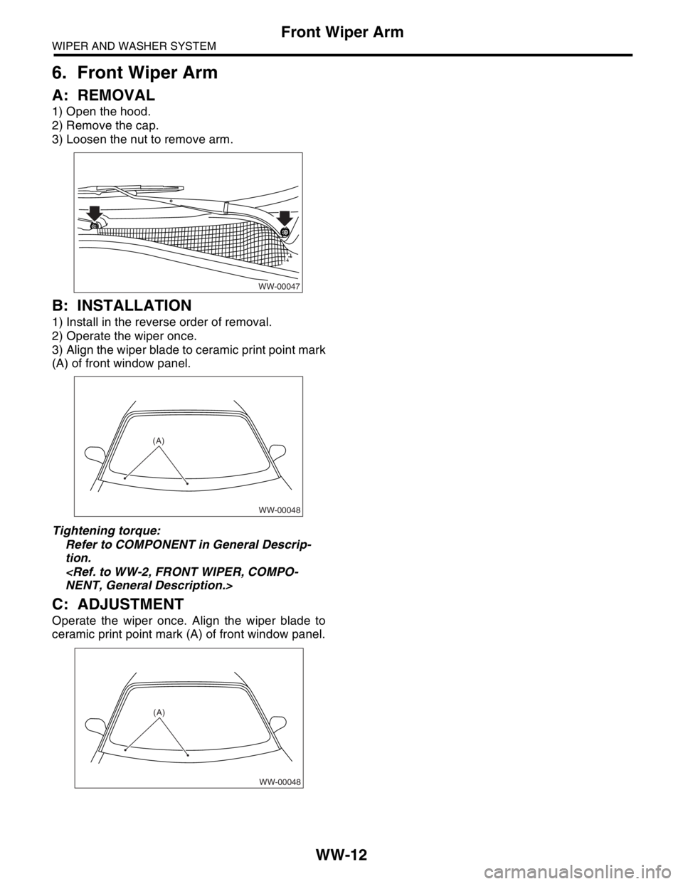
A: REMOVAL
1) Open the hood.
2) Remove the cap.
3) Loosen the nut to remove arm.
B: INSTALLATION
1) Install in the reverse order of removal.
2) Operate the wiper once.
3) Align the wiper blade to ceramic print point mark
(A) of front window panel.
Tightening torque:
Refer to COMPONENT in General Descrip-
tion.
C: ADJUSTMENT
Operate the wiper once. Align the wiper blade to
ceramic print point mark (A) of front window panel.
WW-00047
WW-00048
(A)
WW-00048
(A)
Page 303 of 2870

WW-15
WIPER AND WASHER SYSTEM
Front Washer Nozzle
8. Front Washer Nozzle
A: REMOVAL
1) Remove the washer hose from the washer noz-
zle.
2) Open the clips on the underside of the hood with
a thin screwdriver or other tool, and remove the
washer nozzle.
B: INSTALLATION
1) Install in the reverse order of removal.
NOTE:
Hoses have rib as eyemark for twist-proof.
2) Adjust the position of the washer liquid sprayer.
C: INSPECTION
Make sure the nozzle and hose are not clogged.
Check hoses for twist or fold.
D: ADJUSTMENT
NOTE:
It is not necessary to adjust the washer injection
position because of spreading nozzle type.
WW-00023
Page 421 of 2870

SECURITY AND LOCK
SL
Page
1. General Description ....................................................................................2
2. Door Lock Control System ..........................................................................9
3. Keyless Entry System ...............................................................................14
4. Front Inner Remote ...................................................................................22
5. Front Outer Handle ...................................................................................23
6. Front Door Latch Assembly.......................................................................24
7. Front Door Lock Actuator ..........................................................................25
8. Rear Inner Remote....................................................................................26
9. Rear Outer Handle ....................................................................................27
10. Rear Door Latch Assembly .......................................................................28
11. Rear Door Lock Actuator...........................................................................29
12. Rear Gate Outer Handle ...........................................................................30
13. Rear Gate Latch Assembly .......................................................................31
14. Rear Gate Latch Lock Actuator .................................................................32
15. Front Hood Lock Assembly .......................................................................33
16. Remote Openers .......................................................................................34
17. Ignition Key Lock .......................................................................................35
18. Key Lock Cylinder .....................................................................................36
19. Immobilizer Control Module ......................................................................37
20. Immobilizer Antenna .................................................................................38
21. Keyless Entry Control Module ...................................................................39
22. Double Lock Module .................................................................................40
23. Keyless Transmitter ..................................................................................41
Page 425 of 2870
SL-5
SECURITY AND LOCK
General Description
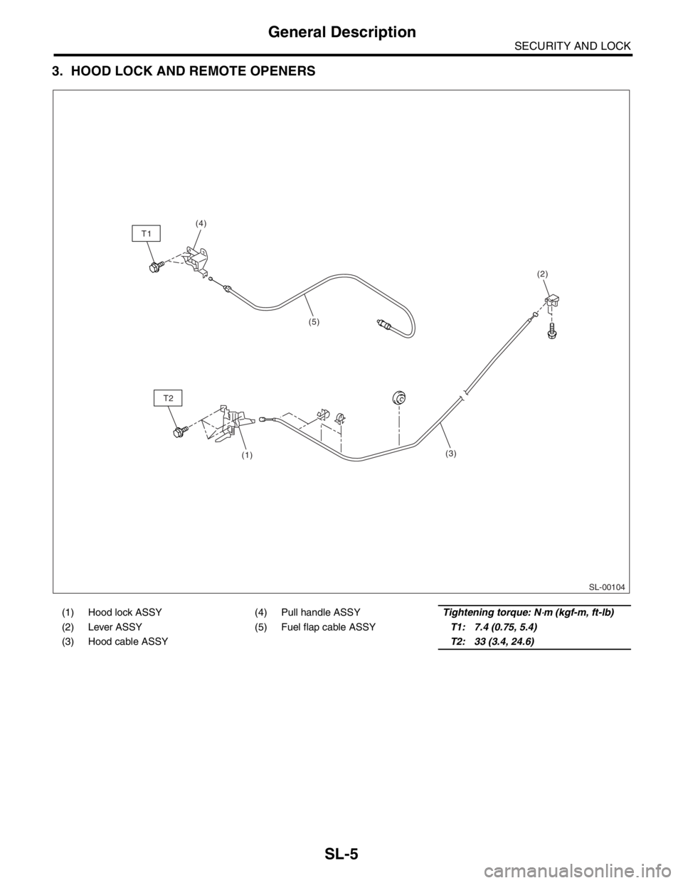
3. HOOD LOCK AND REMOTE OPENERS
(1) Hood lock ASSY (4) Pull handle ASSYTightening torque: N⋅m (kgf-m, ft-lb)
(2) Lever ASSY (5) Fuel flap cable ASSYT1: 7.4 (0.75, 5.4)
(3) Hood cable ASSYT2: 33 (3.4, 24.6)
SL-00104
T1
T2
(5) (4)
(2)
(3)
(1)
Page 453 of 2870
SL-33
SECURITY AND LOCK
Front Hood Lock Assembly
15.Front Hood Lock Assembly
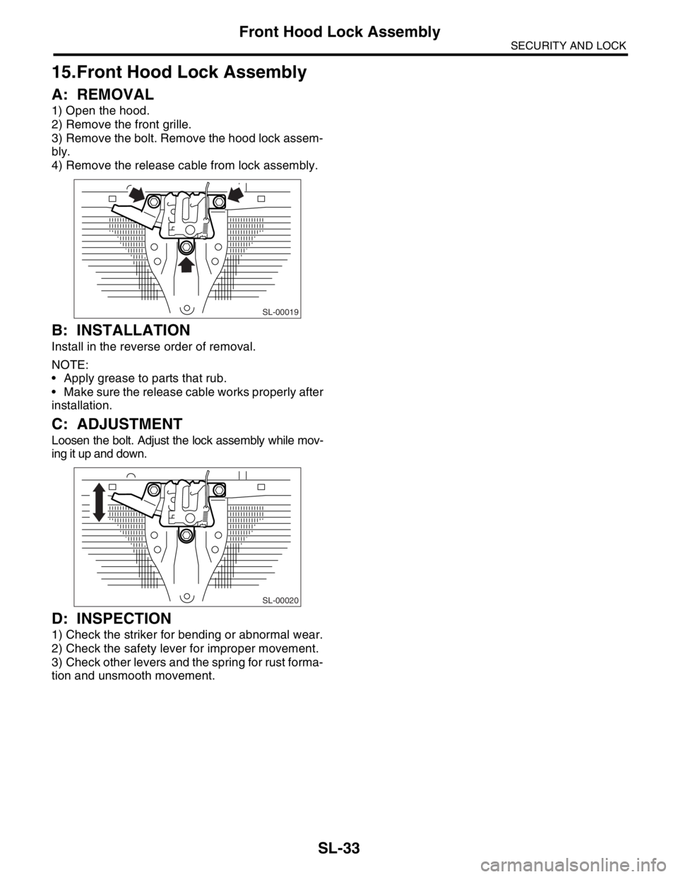
A: REMOVAL
1) Open the hood.
2) Remove the front grille.
3) Remove the bolt. Remove the hood lock assem-
bly.
4) Remove the release cable from lock assembly.
B: INSTALLATION
Install in the reverse order of removal.
NOTE:
Apply grease to parts that rub.
Make sure the release cable works properly after
installation.
C: ADJUSTMENT
Loosen the bolt. Adjust the lock assembly while mov-
ing it up and down.
D: INSPECTION
1) Check the striker for bending or abnormal wear.
2) Check the safety lever for improper movement.
3) Check other levers and the spring for rust forma-
tion and unsmooth movement.
SL-00019
SL-00020
Page 454 of 2870
SL-34
SECURITY AND LOCK
Remote Openers
16.Remote Openers
A: REMOVAL
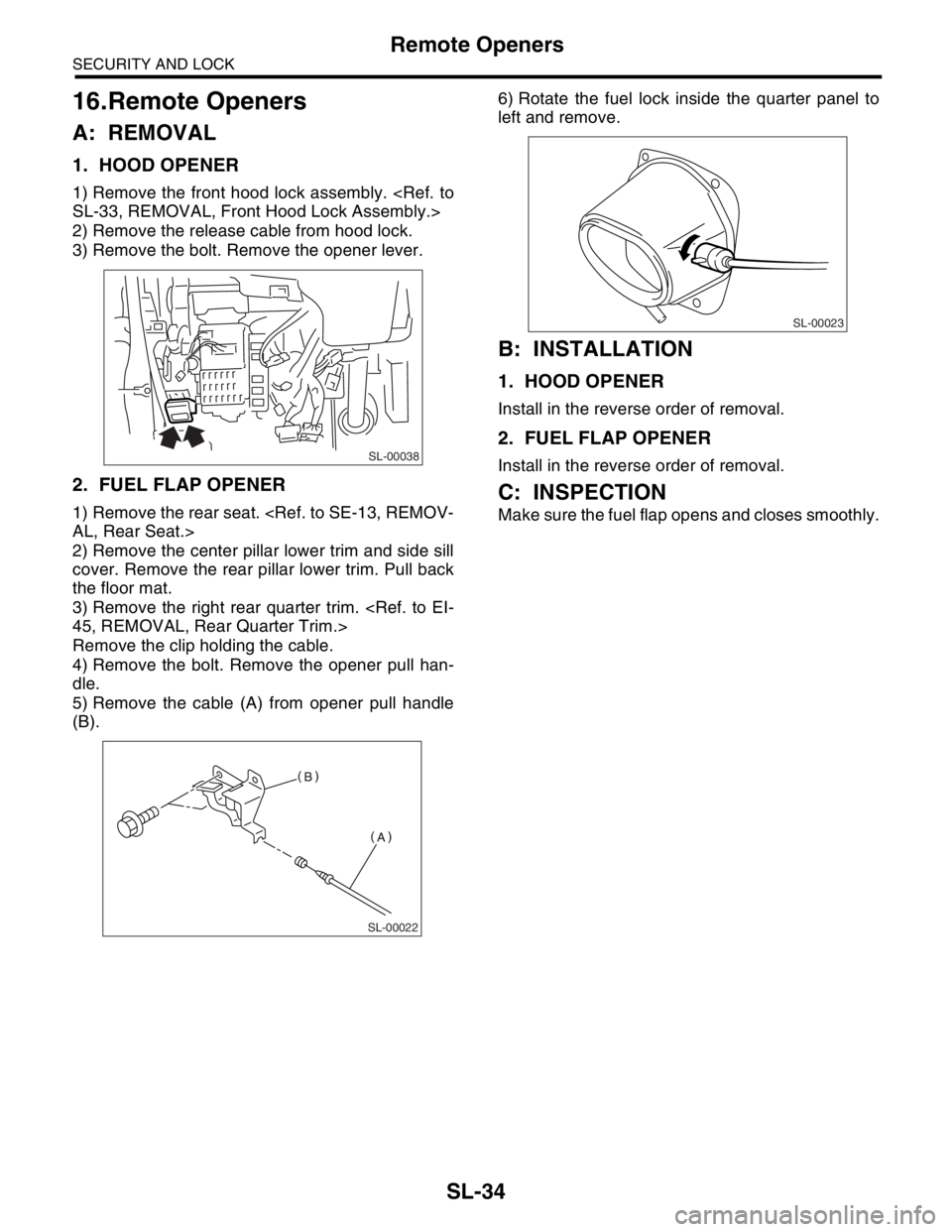
1. HOOD OPENER
1) Remove the front hood lock assembly.
2) Remove the release cable from hood lock.
3) Remove the bolt. Remove the opener lever.
2. FUEL FLAP OPENER
1) Remove the rear seat.
2) Remove the center pillar lower trim and side sill
cover. Remove the rear pillar lower trim. Pull back
the floor mat.
3) Remove the right rear quarter trim.
Remove the clip holding the cable.
4) Remove the bolt. Remove the opener pull han-
dle.
5) Remove the cable (A) from opener pull handle
(B).6) Rotate the fuel lock inside the quarter panel to
left and remove.
B: INSTALLATION
1. HOOD OPENER
Install in the reverse order of removal.
2. FUEL FLAP OPENER
Install in the reverse order of removal.
C: INSPECTION
Make sure the fuel flap opens and closes smoothly.
SL-00038
SL-00022
SL-00023
Page 494 of 2870
EI-18
EXTERIOR/INTERIOR TRIM
Front Grille
2. Front Grille
A: REMOVAL
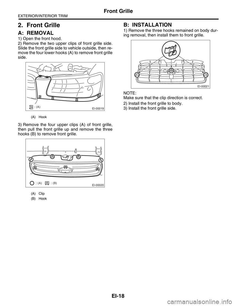
1) Open the front hood.
2) Remove the two upper clips of front grille side.
Slide the front grille side to vehicle outside, then re-
move the four lower hooks (A) to remove front grille
side.
3) Remove the four upper clips (A) of front grille,
then pull the front grille up and remove the three
hooks (B) to remove front grille.
B: INSTALLATION
1) Remove the three hooks remained on body dur-
ing removal, then install them to front grille.
NOTE:
Make sure that the clip direction is correct.
2) Install the front grille to body.
3) Install the front grille side.
(A) Hook
(A) Clip
(B) Hook
EI-00019: (A)
EI-00020: (A) : (B)EI-00021