door lock SUBARU FORESTER 2004 Service Owner's Manual
[x] Cancel search | Manufacturer: SUBARU, Model Year: 2004, Model line: FORESTER, Model: SUBARU FORESTER 2004Pages: 2870, PDF Size: 38.67 MB
Page 449 of 2870
SL-29
SECURITY AND LOCK
Rear Door Lock Actuator
11.Rear Door Lock Actuator
A: REMOVAL
1) Remove the rear door latch assembly.
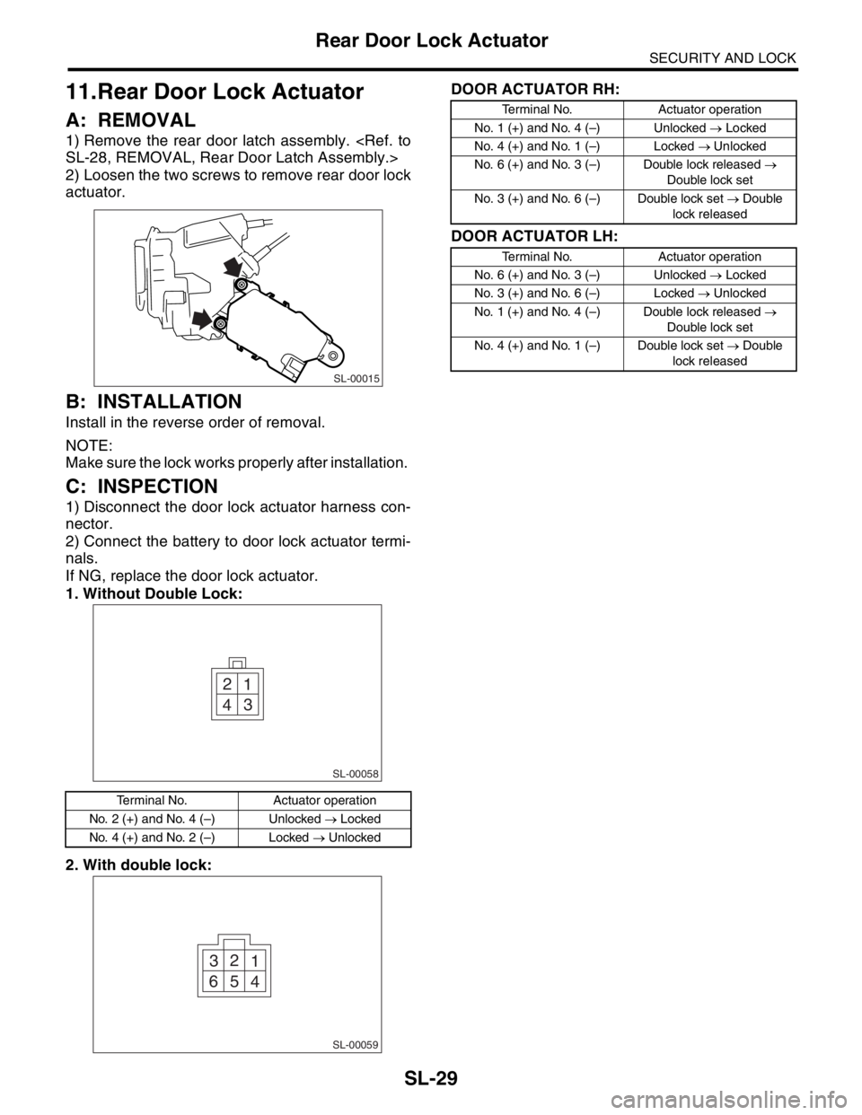
2) Loosen the two screws to remove rear door lock
actuator.
B: INSTALLATION
Install in the reverse order of removal.
NOTE:
Make sure the lock works properly after installation.
C: INSPECTION
1) Disconnect the door lock actuator harness con-
nector.
2) Connect the battery to door lock actuator termi-
nals.
If NG, replace the door lock actuator.
1. Without Double Lock:
2. With double lock:DOOR ACTUATOR RH:
DOOR ACTUATOR LH:
Terminal No. Actuator operation
No. 2 (+) and No. 4 (–) Unlocked → Locked
No. 4 (+) and No. 2 (–) Locked → Unlocked
SL-00015
1 2
3
4
SL-00058
1 2
3
4 5 6
SL-00059
Terminal No. Actuator operation
No. 1 (+) and No. 4 (–) Unlocked → Locked
No. 4 (+) and No. 1 (–) Locked → Unlocked
No. 6 (+) and No. 3 (–) Double lock released →
Double lock set
No. 3 (+) and No. 6 (–) Double lock set → Double
lock released
Terminal No. Actuator operation
No. 6 (+) and No. 3 (–) Unlocked → Locked
No. 3 (+) and No. 6 (–) Locked → Unlocked
No. 1 (+) and No. 4 (–) Double lock released →
Double lock set
No. 4 (+) and No. 1 (–) Double lock set → Double
lock released
Page 451 of 2870
SL-31
SECURITY AND LOCK
Rear Gate Latch Assembly
13.Rear Gate Latch Assembly
A: REMOVAL
1) Disconnect the ground cable from battery.
2) Remove the rear gate trim.
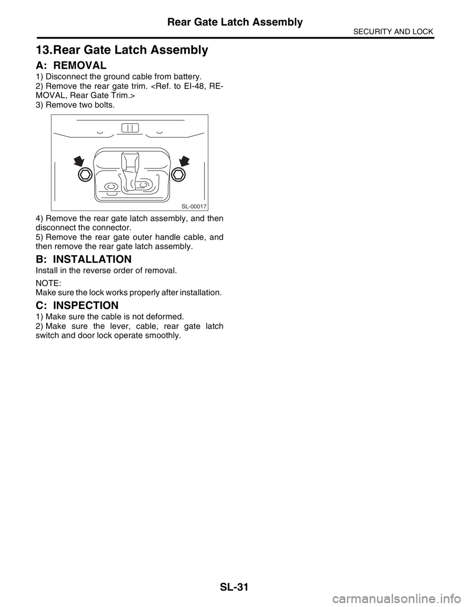
3) Remove two bolts.
4) Remove the rear gate latch assembly, and then
disconnect the connector.
5) Remove the rear gate outer handle cable, and
then remove the rear gate latch assembly.
B: INSTALLATION
Install in the reverse order of removal.
NOTE:
Make sure the lock works properly after installation.
C: INSPECTION
1) Make sure the cable is not deformed.
2) Make sure the lever, cable, rear gate latch
switch and door lock operate smoothly.
SL-00017
Page 452 of 2870
SL-32
SECURITY AND LOCK
Rear Gate Latch Lock Actuator
14.Rear Gate Latch Lock Actua-
tor
A: REMOVAL
1) Remove the rear gate latch assembly.
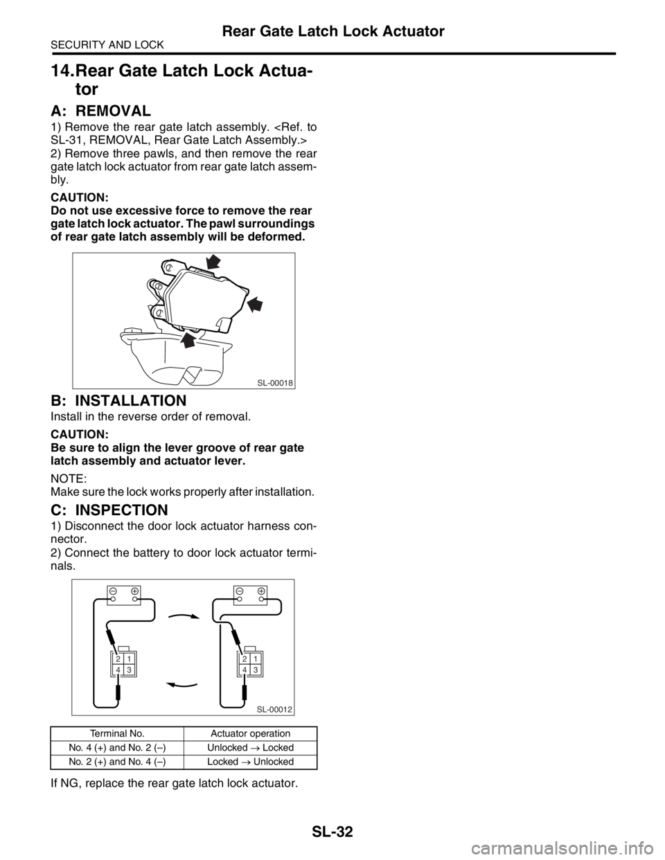
2) Remove three pawls, and then remove the rear
gate latch lock actuator from rear gate latch assem-
bly.
CAUTION:
Do not use excessive force to remove the rear
gate latch lock actuator. The pawl surroundings
of rear gate latch assembly will be deformed.
B: INSTALLATION
Install in the reverse order of removal.
CAUTION:
Be sure to align the lever groove of rear gate
latch assembly and actuator lever.
NOTE:
Make sure the lock works properly after installation.
C: INSPECTION
1) Disconnect the door lock actuator harness con-
nector.
2) Connect the battery to door lock actuator termi-
nals.
If NG, replace the rear gate latch lock actuator.
Terminal No. Actuator operation
No. 4 (+) and No. 2 (–) Unlocked → Locked
No. 2 (+) and No. 4 (–) Locked → Unlocked
SL-00018
SL-00012
21
43
21
43
Page 456 of 2870
SL-36
SECURITY AND LOCK
Key Lock Cylinder
18.Key Lock Cylinder
A: REPLACEMENT
1. FRONT DOOR
Without double lock:
1) Remove the door trim.
2) Pull back the sealing cover.
3) Close the front door glass completely.
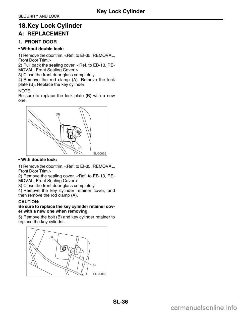
4) Remove the rod clamp (A). Remove the lock
plate (B). Replace the key cylinder.
NOTE:
Be sure to replace the lock plate (B) with a new
one.
With double lock:
1) Remove the door trim.
2) Remove the sealing cover.
3) Close the front door glass completely.
4) Remove the key cylinder retainer cover, and
then remove the rod clamp (A).
CAUTION:
Be sure to replace the key cylinder retainer cov-
er with a new one when removing.
5) Remove the bolt (B) and key cylinder retainer to
replace the key cylinder.
SL-00026
(A) (B)
SL-00060
(A) (B)
Page 461 of 2870

SL-41
SECURITY AND LOCK
Keyless Transmitter
23.Keyless Transmitter
A: REMOVAL
1. TRANSMITTER BATTERY
Remove the battery from transmitter.
NOTE:
To prevent static electricity damage to transmitter
printed circuit board, touch the steel area of building
with hand to discharge the static electricity carried
on body or clothes before disassembling transmitter.
B: INSTALLATION
1. TRANSMITTER BATTERY
Install in the reverse order of removal.
C: INSPECTION
1. TRANSMITTER BATTERY
Measure the voltage between battery (+) terminal
and (–) terminal.
NOTE:
Battery discharge occurs during measurement.
Complete the measurement within 5 seconds.
During battery voltage measurement, voltage
falls more than 1.8 volts in 3 seconds period.If NG, replace the battery. (Use CR1620 or equiva-
lent.)
D: REPLACEMENT
1. TRANSMITTER REGISTRATION
NOTE:
A maximum of three transmitters can be regis-
tered for each individual vehicle.
When replacing the transmitter (key), registration
to immobilizer system is also necessary.
1) Remove the side sill cover at driver’s side, then
connect the registration connectors at front pillar
lower section.
2) Unlock the door lock.
3) Press any button of the transmitter twice while
pressing driver’s door lock switch to unlock side to
be registered.
4) The door lock will automatically lock and unlock
in sequence. This indicates the completion of trans-
mitter registration for first transmitter.
5) If the registration of second and third transmitter
is now to be carried out, repeat the procedure 3)
and 4).
6) Disconnect the registration connectors after the
completion of all registration operations. After con-
firming the operation of door lock using newly reg-
istered transmitter(s), reinstall the side sill cover at
driver’s side.
(A) Resistance 300 Ω
Tester connection
Standard
(+) (–)
Battery (+) termi-
nalBattery (–) termi-
nal2.5 — 3.0 V
SL-00065
SL-00066
(A)
Page 541 of 2870
EB-11
EXTERIOR BODY PANEL
Front Door Panel
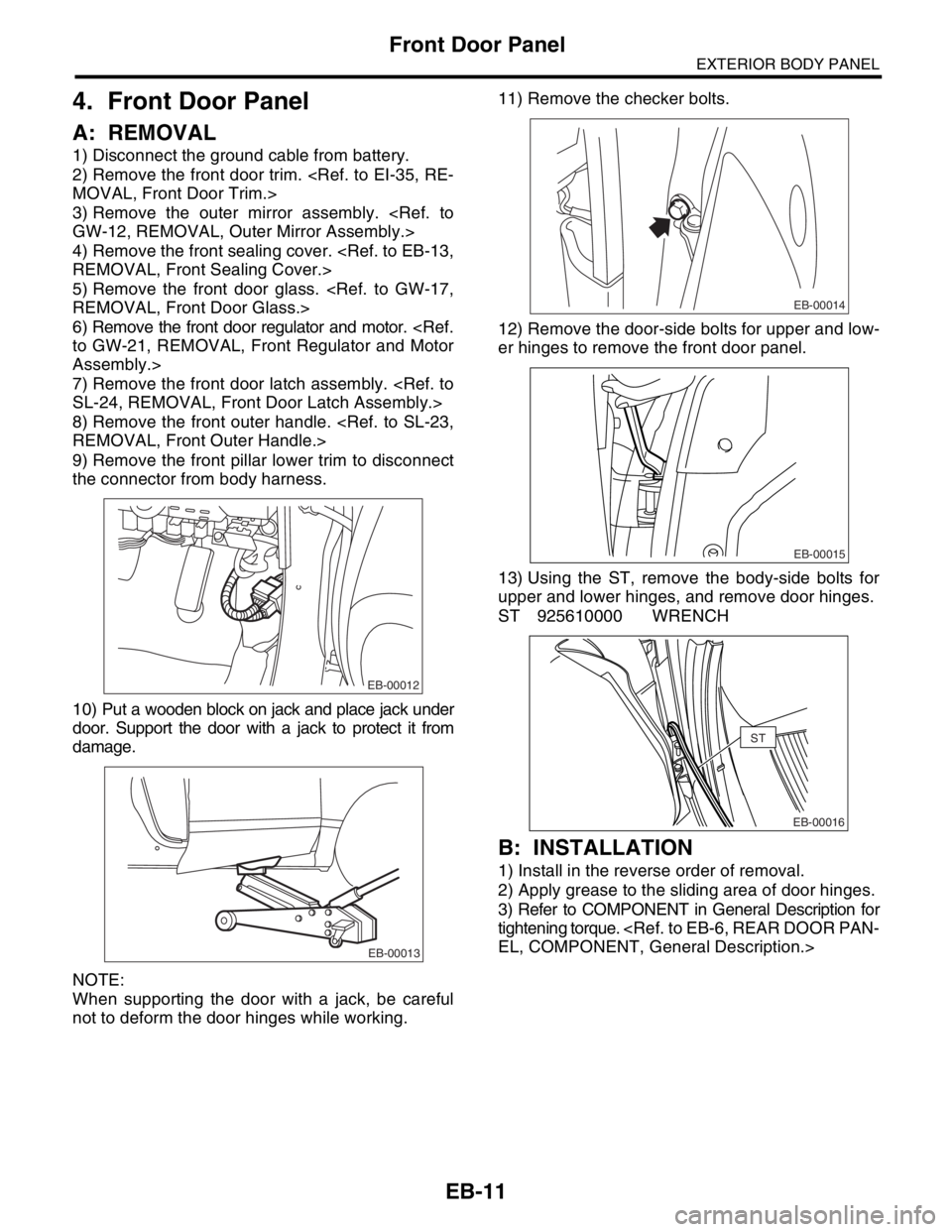
4. Front Door Panel
A: REMOVAL
1) Disconnect the ground cable from battery.
2) Remove the front door trim.
3) Remove the outer mirror assembly.
4) Remove the front sealing cover.
5) Remove the front door glass.
6) Remove the front door regulator and motor.
Assembly.>
7) Remove the front door latch assembly.
8) Remove the front outer handle.
9) Remove the front pillar lower trim to disconnect
the connector from body harness.
10) Put a wooden block on jack and place jack under
door. Support the door with a jack to protect it from
damage.
NOTE:
When supporting the door with a jack, be careful
not to deform the door hinges while working.11) Remove the checker bolts.
12) Remove the door-side bolts for upper and low-
er hinges to remove the front door panel.
13) Using the ST, remove the body-side bolts for
upper and lower hinges, and remove door hinges.
ST 925610000 WRENCH
B: INSTALLATION
1) Install in the reverse order of removal.
2) Apply grease to the sliding area of door hinges.
3) Refer to COMPONENT in General Description for
tightening torque.
EB-00012
EB-00013
EB-00014
EB-00015
EB-00016
ST
Page 544 of 2870
EB-14
EXTERIOR BODY PANEL
Rear Door Panel
6. Rear Door Panel
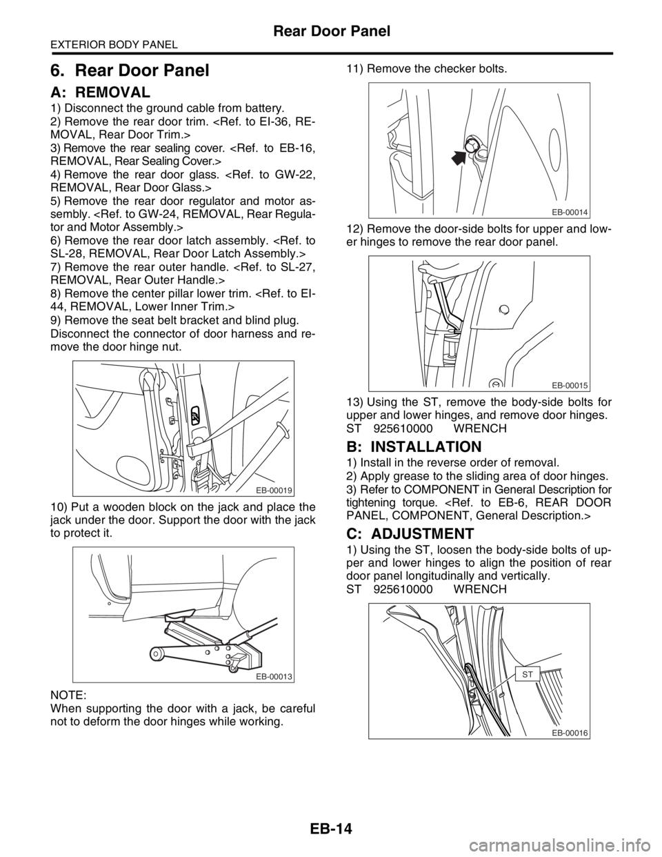
A: REMOVAL
1) Disconnect the ground cable from battery.
2) Remove the rear door trim.
3) Remove the rear sealing cover.
4) Remove the rear door glass.
5) Remove the rear door regulator and motor as-
sembly.
6) Remove the rear door latch assembly.
7) Remove the rear outer handle.
8) Remove the center pillar lower trim.
9) Remove the seat belt bracket and blind plug.
Disconnect the connector of door harness and re-
move the door hinge nut.
10) Put a wooden block on the jack and place the
jack under the door. Support the door with the jack
to protect it.
NOTE:
When supporting the door with a jack, be careful
not to deform the door hinges while working.11) Remove the checker bolts.
12) Remove the door-side bolts for upper and low-
er hinges to remove the rear door panel.
13) Using the ST, remove the body-side bolts for
upper and lower hinges, and remove door hinges.
ST 925610000 WRENCH
B: INSTALLATION
1) Install in the reverse order of removal.
2) Apply grease to the sliding area of door hinges.
3) Refer to COMPONENT in General Description for
tightening torque.
C: ADJUSTMENT
1) Using the ST, loosen the body-side bolts of up-
per and lower hinges to align the position of rear
door panel longitudinally and vertically.
ST 925610000 WRENCH
EB-00019
EB-00013
EB-00014
EB-00015
EB-00016
ST
Page 726 of 2870

PI-3
PRE-DELIVERY INSPECTION
Pre-delivery Inspection
B: PDI PROCEDURE
Follow the procedures shown in the table below.
Static Checks Just After Vehicle Receipt
Step Check point
1. Appearance check (1) If the vehicle is covered with protective coating, visually check the vehicle
body for damage and dents. If the protective coating has been removed,
visually check the body paints for small areas of damage or stains.
(2) Visually check the glass and light lenses for any damage and cracks or
excessive gaps to the body sheet metal.
(3) Visually check the plated parts for any damage.
2. Tire check (1) Check the tires for damage, abnormal conditions, and dents on the
wheels.
(2) Check the tire air pressure.
3. Fuse installation If the vehicle is about to be delivered to the customer, attach a room light
fuse.
4. Connection of air conditioner harness If the vehicle is about to be delivered to the customer, connect the air condi-
tioner harness.
5. Check the doors for lock/unlock and open/close
operations.(1) Using the key, check if the door can be locked and unlocked normally.
(2) Open and close all doors to see that there are no abnormal conditions.
6. Operation check of double lock Check that the double lock operates normally.
7. Operation check of the child safety lock system. Check the child safety lock system operates normally.
8. Check the rear gate for lock/unlock and open/
close operations.(1) Check if the rear gate can be unlocked normally from the emergency
door.
(2) Open and close the rear gate to see that there are no abnormal condi-
tions.
(3) Operate the power door locking switch to check that the rear gate is
locked and unlocked normally.
9. Operation check of fuel lid opener lock release
leverOperate the fuel lid opener to check that the fuel lid is unlocked normally.
10. Accessory check Check that the following accessories are provided:
Owner’s manual
Warranty booklet
Service booklet
Spare key
Jack
Tool set
Spare tire
11. Operation check of hood lock release system Operate the hood lock release lever to check that the hood opens normally.
12. Battery Check the battery for any abnormal conditions such as rust and trace of bat-
tery fluid leaks.
13. Brake fluid Check the fluid amount.
14. Engine oil Check the oil amount.
15. Transmission fluid (1) Check the fluid amount.
(2) For AT, check the front differential oil.
16. AT front differential oil Check the AT front differential oil amount.
17. Coolant Check the coolant amount.
18. Clutch fluid Check the clutch fluid amount.
19. Window washer fluid Check the window washer fluid amount.
20. Hood latch check Check that the hood is closed and latched securely.
21. Keyless entry system Check that the keyless entry system operates normally.
22. Security system Check that the security system operates normally.
23. Seat (1) Check the seat surfaces for smears or dirt.
(2) Check the seat installation conditions and functionality.
24. Seat belt Check the seat belt installation conditions and functionality.
25. Wheel alignment Check that the wheel alignments are properly adjusted.
Page 728 of 2870
PI-5
PRE-DELIVERY INSPECTION
Pre-delivery Inspection
1. APPEARANCE CHECK
1) If the vehicle is covered with protective coating,
visually check the vehicle body for damage and
dents.
2) If there is no protective coating, check the body
paints for small areas of damage or stains and re-
pair as necessary.
3) Check the window glass, door glass, and lights
for any cracks or damage and repair or replace the
parts as necessary.
4) Check the plated parts, such as the grilles and
door knobs, for damage or loss of gloss and repair
or replace the parts as necessary.
2. TIRE CHECK
Check the tire outer faces for any damage.
Check the tire air pressure by referring to the fol-
lowing table.
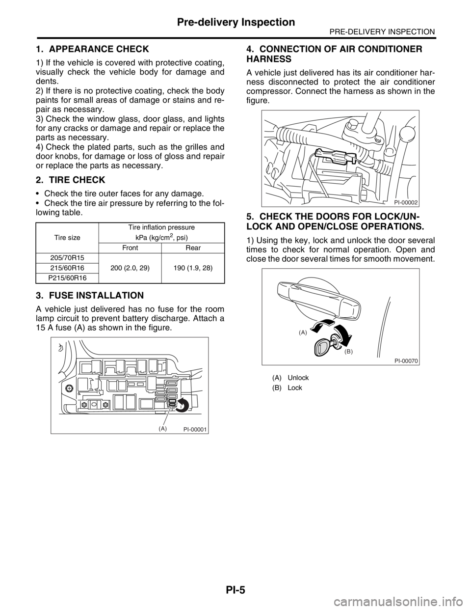
3. FUSE INSTALLATION
A vehicle just delivered has no fuse for the room
lamp circuit to prevent battery discharge. Attach a
15 A fuse (A) as shown in the figure.
4. CONNECTION OF AIR CONDITIONER
HARNESS
A vehicle just delivered has its air conditioner har-
ness disconnected to protect the air conditioner
compressor. Connect the harness as shown in the
figure.
5. CHECK THE DOORS FOR LOCK/UN-
LOCK AND OPEN/CLOSE OPERATIONS.
1) Using the key, lock and unlock the door several
times to check for normal operation. Open and
close the door several times for smooth movement.Tire sizeTire inflation pressure
kPa (kg/cm2, psi)
Front Rear
205/70R15
200 (2.0, 29) 190 (1.9, 28) 215/60R16
P215/60R16
PI-00001(A)
(A) Unlock
(B) Lock
PI-00002
PI-00070
(A)
(B)
Page 729 of 2870
PI-6
PRE-DELIVERY INSPECTION
Pre-delivery Inspection
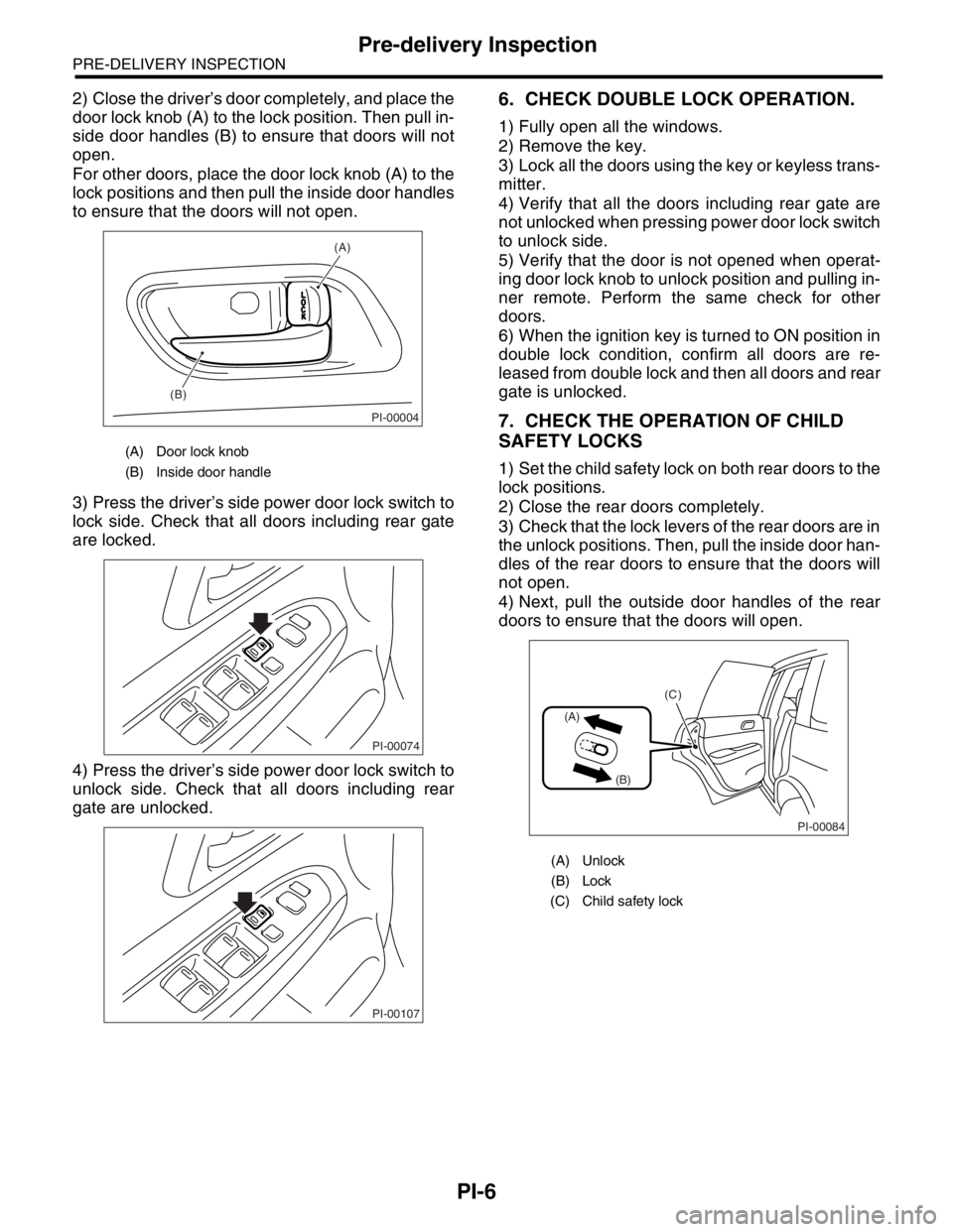
2) Close the driver’s door completely, and place the
door lock knob (A) to the lock position. Then pull in-
side door handles (B) to ensure that doors will not
open.
For other doors, place the door lock knob (A) to the
lock positions and then pull the inside door handles
to ensure that the doors will not open.
3) Press the driver’s side power door lock switch to
lock side. Check that all doors including rear gate
are locked.
4) Press the driver’s side power door lock switch to
unlock side. Check that all doors including rear
gate are unlocked.6. CHECK DOUBLE LOCK OPERATION.
1) Fully open all the windows.
2) Remove the key.
3) Lock all the doors using the key or keyless trans-
mitter.
4) Verify that all the doors including rear gate are
not unlocked when pressing power door lock switch
to unlock side.
5) Verify that the door is not opened when operat-
ing door lock knob to unlock position and pulling in-
ner remote. Perform the same check for other
doors.
6) When the ignition key is turned to ON position in
double lock condition, confirm all doors are re-
leased from double lock and then all doors and rear
gate is unlocked.
7. CHECK THE OPERATION OF CHILD
SAFETY LOCKS
1) Set the child safety lock on both rear doors to the
lock positions.
2) Close the rear doors completely.
3) Check that the lock levers of the rear doors are in
the unlock positions. Then, pull the inside door han-
dles of the rear doors to ensure that the doors will
not open.
4) Next, pull the outside door handles of the rear
doors to ensure that the doors will open.
(A) Door lock knob
(B) Inside door handle
PI-00004
(A)
(B)
PI-00074
PI-00107
(A) Unlock
(B) Lock
(C) Child safety lock
PI-00084
(A)
(B)
(C)