compressor SUBARU FORESTER 2004 Service Service Manual
[x] Cancel search | Manufacturer: SUBARU, Model Year: 2004, Model line: FORESTER, Model: SUBARU FORESTER 2004Pages: 2870, PDF Size: 38.67 MB
Page 1128 of 2870
![SUBARU FORESTER 2004 Service Service Manual EN(H4SO)-30
ENGINE (DIAGNOSTIC)
Subaru Select Monitor
4. READ CURRENT DATA FOR ENGINE. (NORMAL MODE)
1) On the «Main Menu» display screen, select the {Each System Check} and press the [YES] key.
2)](/img/17/57426/w960_57426-1127.png "SUBARU FORESTER 2004 Service Service Manual EN(H4SO)-30
ENGINE (DIAGNOSTIC)
Subaru Select Monitor
4. READ CURRENT DATA FOR ENGINE. (NORMAL MODE)
1) On the «Main Menu» display screen, select the {Each System Check} and press the [YES] key.
2)")
EN(H4SO)-30
ENGINE (DIAGNOSTIC)
Subaru Select Monitor
4. READ CURRENT DATA FOR ENGINE. (NORMAL MODE)
1) On the «Main Menu» display screen, select the {Each System Check} and press the [YES] key.
2) On the «System Selection Menu» display screen, select the {Engine} and press the [YES] key.
3) Press the [YES] key after the information of engine type was displayed.
4) On the «Engine Diagnosis» display screen, select the {Current Data Display/Save}, and then press the
[YES] key.
5) On the «Data Display Menu» display screen, select the {Data Display} and press the [YES] key.
6) Using the scroll key, scroll the display screen up or down until the desired data is shown.
A list of the support data is shown in the following table.
Description Display Unit of measure
Battery voltage Battery Voltage V
Vehicle speed signal Meter vehicle speed km/h or MPH
Engine speed signal Engine speed rpm
Engine coolant temperature signal Engine coolant temperature°C or (°F)
Ignition timing signal Ignition timing deg
Throttle position signal Amount of intake air %
Throttle position signal Throttle Sensor Voltage V
Injection pulse width Fuel injection pulse width ms
Idle air control signal ISC Steps STEP
Engine load data Engine load %
Front oxygen (A/F) sensor resistance A/F sensor resistance value 1 ohm
Front oxygen (A/F) sensor output signal A/F sensor current value 1 —
Rear oxygen sensor output signalRear oxygen sensor voltage
valueV
Short term fuel trim A/F Compensation 1 %
Knock sensor signal Knock Correction deg
Atmospheric absolute pressure signal Atmospheric pressure mmHg, kPa, inHg or psi
Intake manifold relative pressure signal Mani. Relative Pressure mmHg, kPa, inHg or psi
Intake manifold absolute pressure signalIntake manifold absolute pres-
suremmHg, kPa, inHg or psi
A/F correction (short term fuel trim) by rear oxygen sensor A/F Compensation 3 %
Long term whole fuel trim A/F learning 1 %
Front oxygen (A/F) sensor heater current Front O2 heater current value A
Rear oxygen sensor heater current Rear O2 heater current value A
Canister purge control solenoid valve duty ratio CPC Valve Duty Ratio %
Fuel level signal Fuel level voltage V
Intake air temperature signal Intake air temperature°C or (°F)
Learned ignition timing Ignition learning value deg
EGR signal EGR Steps STEP
Ignition switch signal Ignition SW ON or OFF
Test mode connector signal Test mode signal ON or OFF
Neutral position switch signal Neutral SW ON or OFF
Air conditioning switch signal A/C SW ON or OFF
Air conditioning compressor signal A/C Compressor Signal ON or OFF
Radiator main fan relay signal Radiator fan relay 1 ON or OFF
Fuel pump relay signal Fuel pump relay ON or OFF
Knocking signal Knock signal ON or OFF
Radiator sub fan relay signal Radiator fan relay 2 ON or OFF
Power steering switch signal Power steering SW input signal ON or OFF
Engine torque control signal #1 AT coordinate request signal 1 ON or OFF
Engine torque control signal #2 AT coordinate request signal 2 ON or OFF
Page 1132 of 2870
![SUBARU FORESTER 2004 Service Service Manual EN(H4SO)-34
ENGINE (DIAGNOSTIC)
Subaru Select Monitor
7. LED OPERATION MODE FOR ENGINE
1) On the «Main Menu» display screen, select the {Each System Check} and press the [YES] key.
2) On the «Syste](/img/17/57426/w960_57426-1131.png "SUBARU FORESTER 2004 Service Service Manual EN(H4SO)-34
ENGINE (DIAGNOSTIC)
Subaru Select Monitor
7. LED OPERATION MODE FOR ENGINE
1) On the «Main Menu» display screen, select the {Each System Check} and press the [YES] key.
2) On the «Syste")
EN(H4SO)-34
ENGINE (DIAGNOSTIC)
Subaru Select Monitor
7. LED OPERATION MODE FOR ENGINE
1) On the «Main Menu» display screen, select the {Each System Check} and press the [YES] key.
2) On the «System Selection Menu» display screen, select the {Engine} and press the [YES] key.
3) Press the [YES] key after the information of engine type was displayed.
4) On the «Engine Diagnosis» display screen, select the {Current Data Display/Save}, and then press the
[YES] key.
5) On the «Data Display Menu» display screen, select the {Data & LED Display} and press the [YES] key.
6) Using the scroll key, scroll the display screen up or down until the desired data is shown.
A list of the support data is shown in the following table.
NOTE:
For detailed operation procedure, refer to the “SUBARU SELECT MONITOR OPERATION MANUAL”.
Description Display Message LED “ON” requirements
Ignition switch signal Ignition SW ON or OFF When ignition switch is ON
Test mode connector signal Test mode signal ON or OFF When test mode connector is connected.
Neutral position switch signal Neutral SW ON or OFF When neutral position signal is entered.
Air conditioning switch signal A/C SW ON or OFF When air conditioning switch is ON
Air conditioning relay signal A/C Compressor Relay ON or OFF When air conditioning relay is in function.
Radiator main fan relay signal Radiator fan relay 1 ON or OFF When radiator main fan relay is in function.
Fuel pump relay signal Fuel pump relay ON or OFF When fuel pump relay is in function.
Knocking signal Knock signal ON or OFF When knocking signal is input.
Radiator sub fan relay signal Radiator fan relay 2 ON or OFF When radiator sub fan relay is in function.
Engine torque control signal #1 AT coordinate request signal 1 ON or OFFWhen engine torque control signal 1 is
entered
Engine torque control signal #2 AT coordinate request signal 2 ON or OFFWhen engine torque control signal 2 is
entered
Engine torque control permission
signalAT coordinate permission sig-
nalON or OFFWhen engine torque control permission sig-
nal is entered.
Front oxygen (A/F) sensor rich sig-
nalFront O2 Rich Signal #1 ON or OFFWhen front oxygen (A/F) sensor mixture ratio
is rich.
Rear oxygen sensor rich signal RrO2 monitor ON or OFFWhen rear oxygen sensor mixture ratio is
rich.
Starter switch signal Starter SW ON or OFF When starter switch signal is entered.
Idle switch signal Idle Switch Signal ON or OFF When idle switch signal is entered.
Crankshaft position sensor signal Crankshaft position signal ON or OFFWhen crankshaft position sensor signal is
input.
Camshaft position sensor signal Camshaft position signal ON or OFFWhen camshaft position sensor signal is
entered.
Page 1144 of 2870

EN(H4SO)-46
ENGINE (DIAGNOSTIC)
Compulsory Valve Operation Check Mode
A list of the support data is shown in the following
table.
NOTE:
“EGR solenoid” is not indicated but EGR sole-
noid valve is installed to the vehicle.
The following parts will be displayed but not func-
tional because vehicle are not equipped with them.
For detailed operation procedure, refer to the
SUBARU SELECT MONITOR OPERATION MAN-
UAL.
Description Display
Compulsory fuel pump relay oper-
ation checkFuel Pump
Compulsory radiator fan relay
operation checkRadiator Fan Relay
Compulsory air conditioning relay
operation checkA/C Compressor Relay
Compulsory purge control sole-
noid valve operation checkCPC Solenoid
Display
ASV Solenoid
FICD Solenoid
Pressure switching solenoid 1
Pressure switching solenoid 2
PCV Solenoid
Vent Control Solenoid
Atmospheric pressure switching solenoid
Page 1488 of 2870

ME(H4DOTC)-32
MECHANICAL
Idle Speed
3. Idle Speed
A: INSPECTION
1. USING SUBARU SELECT MONITOR
1) Before checking the idle speed, check the fol-
lowing:
(1) Ensure the air cleaner element is free from
clogging, ignition timing is correct, spark plugs
are in good condition, and that the hoses are
connected properly.
(2) Ensure the malfunction indicator light does
not illuminate.
2) Warm-up the engine.
3) Stop the engine, and then turn the ignition switch
to OFF.
4) Insert the cartridge to Subaru Select Monitor.
5) Connect the Subaru Select Monitor to data link
connector.
6) Turn the ignition switch to ON, and Subaru Se-
lect Monitor switch to ON.
7) Select the {2. Each System Check} in Main
Menu.
8) Select the {Engine Control System} in Selection
Menu.
9) Select the {1. Current Data Display & Save} in
Engine Control System Diagnosis.
10) Select the {1.12 Data Display} in Data Display
Menu.
11) Start the engine, and then read the engine idle
speed.
12) Check the idle speed when unloaded. (With
headlights, heater fan, rear defroster, radiator fan,
air conditioning, etc. OFF)
Idle speed [No load and gears in neutral]:
700
±100 rpm
13) Check the idle speed when loaded. (Turn the
air conditioning switch to “ON” and operate the
compressor for at least 1 minute before measure-
ment.)
Idle speed [A/C “ON”, no load and gears in neu-
tral]:
A/C Refrigerant pressure (LOW)
MT: 725
±100 rpm
AT: 750
±100 rpm
A/C Refrigerant pressure (HIGH)
MT: 800
±100 rpm
AT: 825
±100 rpm
NOTE:
As idle speed is controlled by the automatic adjust-
ment type, it can not be adjusted manually. If the
idle speed is out of specifications, refer to General
On-board Diagnosis Table under “Engine Control
System”.
Page 1499 of 2870
ME(H4DOTC)-41
MECHANICAL
Engine Assembly
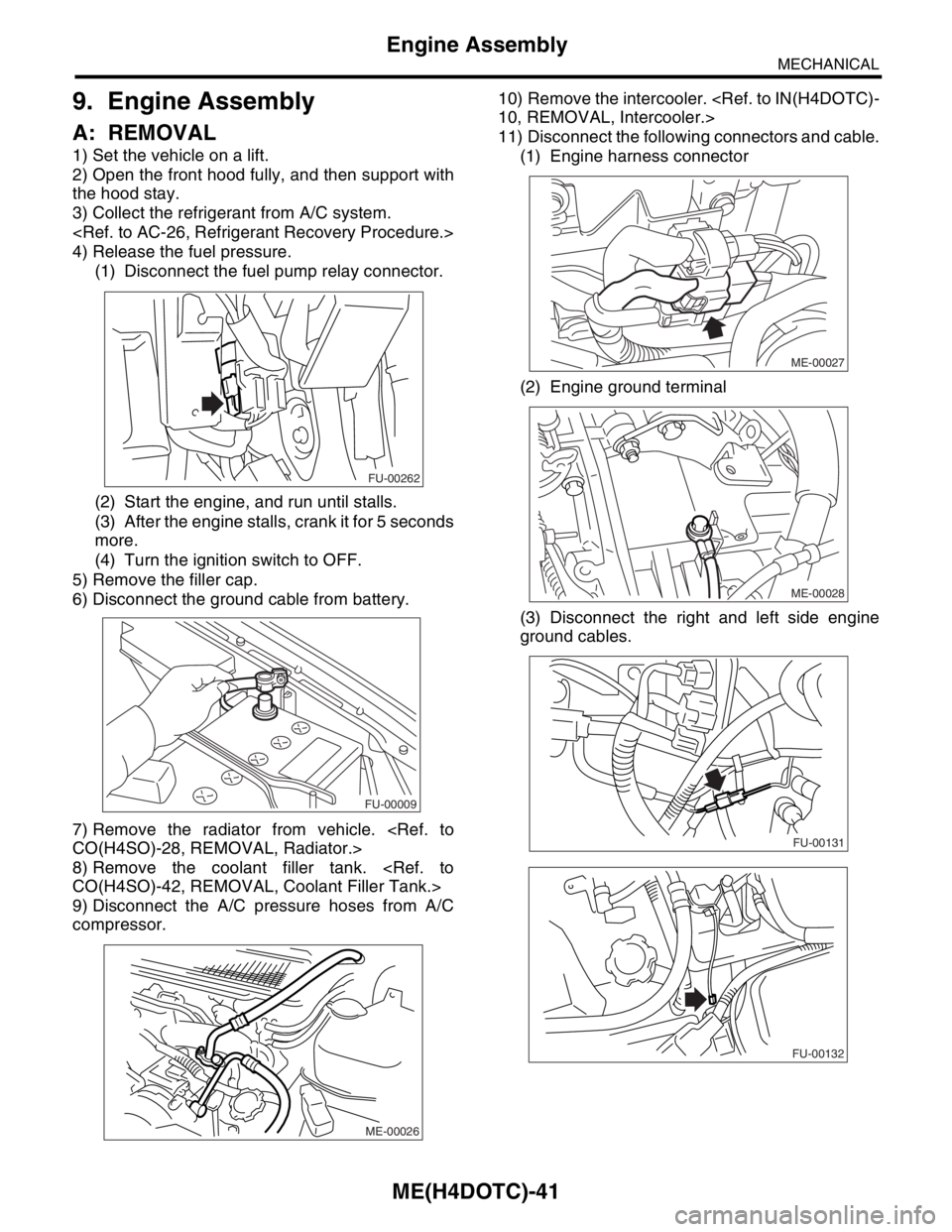
9. Engine Assembly
A: REMOVAL
1) Set the vehicle on a lift.
2) Open the front hood fully, and then support with
the hood stay.
3) Collect the refrigerant from A/C system.
4) Release the fuel pressure.
(1) Disconnect the fuel pump relay connector.
(2) Start the engine, and run until stalls.
(3) After the engine stalls, crank it for 5 seconds
more.
(4) Turn the ignition switch to OFF.
5) Remove the filler cap.
6) Disconnect the ground cable from battery.
7) Remove the radiator from vehicle.
8) Remove the coolant filler tank.
9) Disconnect the A/C pressure hoses from A/C
compressor.10) Remove the intercooler.
11) Disconnect the following connectors and cable.
(1) Engine harness connector
(2) Engine ground terminal
(3) Disconnect the right and left side engine
ground cables.
FU-00262
FU-00009
ME-00026
ME-00027
ME-00028
FU-00131
FU-00132
Page 1500 of 2870
ME(H4DOTC)-42
MECHANICAL
Engine Assembly
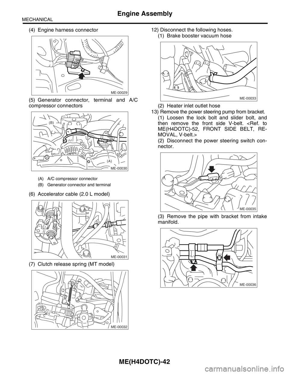
(4) Engine harness connector
(5) Generator connector, terminal and A/C
compressor connectors
(6) Accelerator cable (2.0 L model)
(7) Clutch release spring (MT model)12) Disconnect the following hoses.
(1) Brake booster vacuum hose
(2) Heater inlet outlet hose
13) Remove the power steering pump from bracket.
(1) Loosen the lock bolt and slider bolt, and
then remove the front side V-belt.
MOVAL, V-belt.>
(2) Disconnect the power steering switch con-
nector.
(3) Remove the pipe with bracket from intake
manifold.
(A) A/C compressor connector
(B) Generator connector and terminal
ME-00029
ME-00030
(A) (B)
ME-00031
ME-00032
ME-00033
ME-00035
ME-00036
Page 1506 of 2870
ME(H4DOTC)-48
MECHANICAL
Engine Assembly
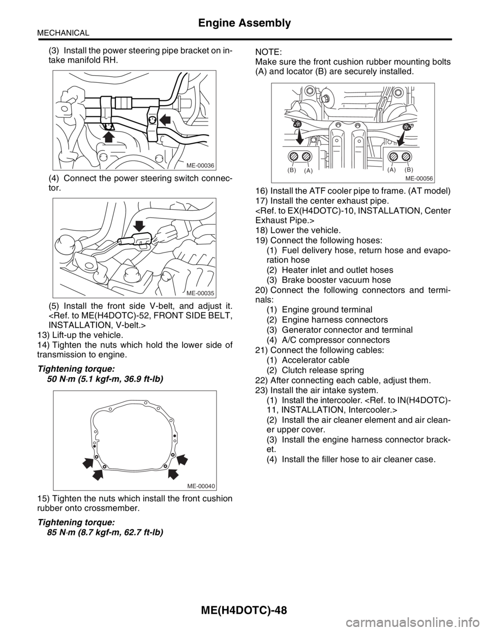
(3) Install the power steering pipe bracket on in-
take manifold RH.
(4) Connect the power steering switch connec-
tor.
(5) Install the front side V-belt, and adjust it.
13) Lift-up the vehicle.
14) Tighten the nuts which hold the lower side of
transmission to engine.
Tightening torque:
50 N
⋅m (5.1 kgf-m, 36.9 ft-lb)
15) Tighten the nuts which install the front cushion
rubber onto crossmember.
Tightening torque:
85 N
⋅m (8.7 kgf-m, 62.7 ft-lb)NOTE:
Make sure the front cushion rubber mounting bolts
(A) and locator (B) are securely installed.
16) Install the ATF cooler pipe to frame. (AT model)
17) Install the center exhaust pipe.
18) Lower the vehicle.
19) Connect the following hoses:
(1) Fuel delivery hose, return hose and evapo-
ration hose
(2) Heater inlet and outlet hoses
(3) Brake booster vacuum hose
20) Connect the following connectors and termi-
nals:
(1) Engine ground terminal
(2) Engine harness connectors
(3) Generator connector and terminal
(4) A/C compressor connectors
21) Connect the following cables:
(1) Accelerator cable
(2) Clutch release spring
22) After connecting each cable, adjust them.
23) Install the air intake system.
(1) Install the intercooler.
(2) Install the air cleaner element and air clean-
er upper cover.
(3) Install the engine harness connector brack-
et.
(4) Install the filler hose to air cleaner case.
ME-00036
ME-00035
ME-00040
ME-00056
(A)
(A)(B)
(B)
Page 1511 of 2870
ME(H4DOTC)-53
MECHANICAL
V-belt
2. REAR SIDE BELT
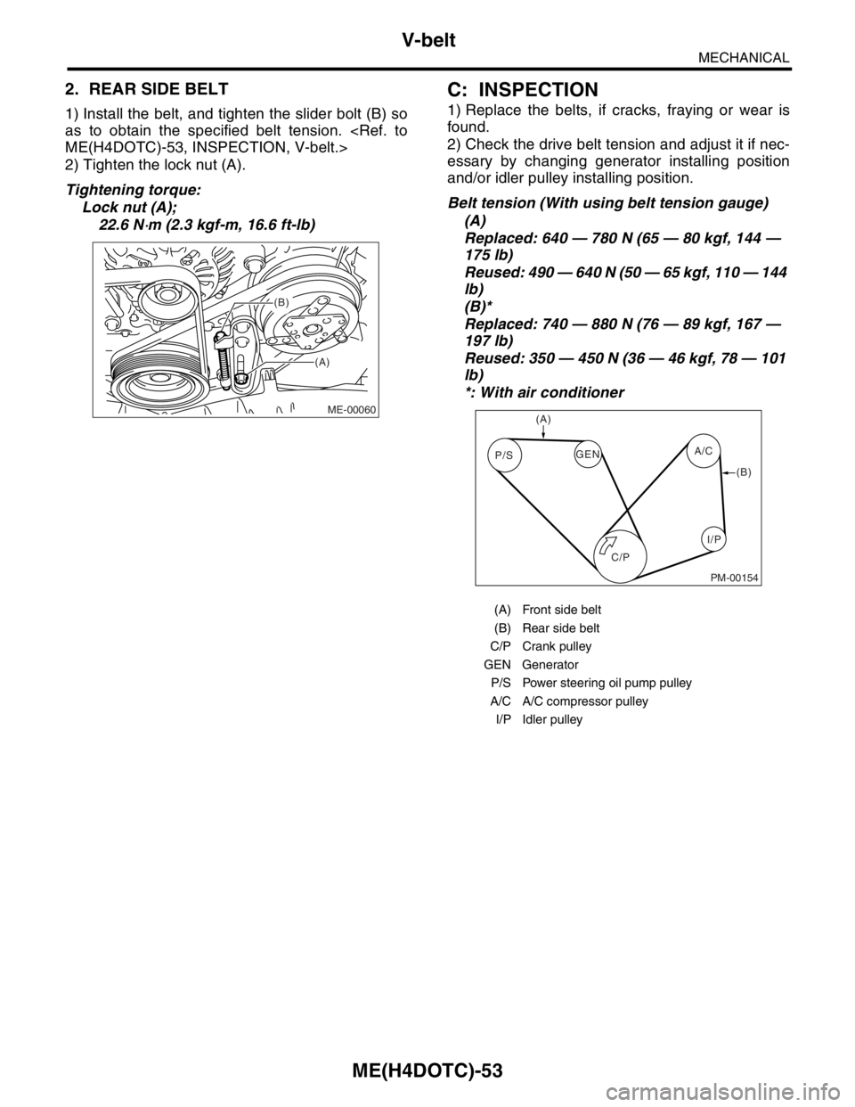
1) Install the belt, and tighten the slider bolt (B) so
as to obtain the specified belt tension.
2) Tighten the lock nut (A).
Tightening torque:
Lock nut (A);
22.6 N
⋅m (2.3 kgf-m, 16.6 ft-lb)
C: INSPECTION
1) Replace the belts, if cracks, fraying or wear is
found.
2) Check the drive belt tension and adjust it if nec-
essary by changing generator installing position
and/or idler pulley installing position.
Belt tension (With using belt tension gauge)
(A)
Replaced: 640 — 780 N (65 — 80 kgf, 144 —
175 lb)
Reused: 490 — 640 N (50 — 65 kgf, 110 — 144
lb)
(B)*
Replaced: 740 — 880 N (76 — 89 kgf, 167 —
197 lb)
Reused: 350 — 450 N (36 — 46 kgf, 78 — 101
lb)
*: With air conditioner
(A)
(B)
ME-00060
(A) Front side belt
(B) Rear side belt
C/P Crank pulley
GEN Generator
P/S Power steering oil pump pulley
A/C A/C compressor pulley
I/P Idler pulley
C/P P/SA/C
GEN
(A)
(B)
I/P
PM-00154
Page 1512 of 2870
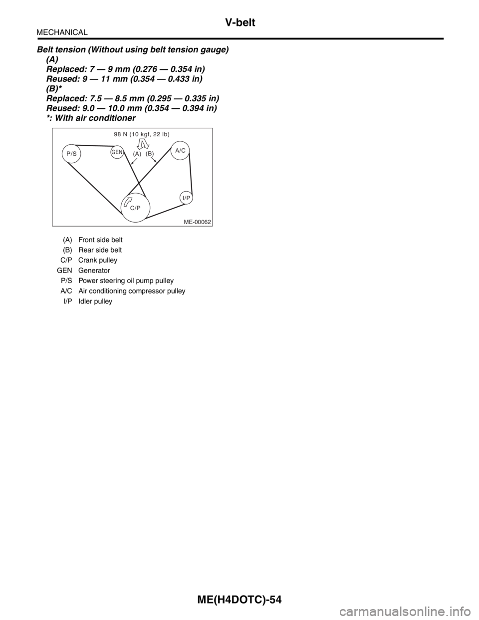
ME(H4DOTC)-54
MECHANICAL
V-belt
Belt tension (Without using belt tension gauge)
(A)
Replaced: 7 — 9 mm (0.276 — 0.354 in)
Reused: 9 — 11 mm (0.354 — 0.433 in)
(B)*
Replaced: 7.5 — 8.5 mm (0.295 — 0.335 in)
Reused: 9.0 — 10.0 mm (0.354 — 0.394 in)
*: With air conditioner
(A) Front side belt
(B) Rear side belt
C/P Crank pulley
GEN Generator
P/S Power steering oil pump pulley
A/C Air conditioning compressor pulley
I/P Idler pulley
ME-00062
P/S
C/PGEN
I/P A/C 98 N (10 kgf, 22 lb)
(A)(B)
Page 1533 of 2870

ME(H4DOTC)-75
MECHANICAL
Cylinder Head Assembly
19.Cylinder Head Assembly
A: REMOVAL
1) Remove the V-belt.
2) Remove the crank pulley.
3) Remove the timing belt cover.
4) Remove the timing belt assembly.
bly.>
5) Remove the cam sprocket.
6) Remove the intake manifold.
7) Remove the bolt which installs the A/C compres-
sor bracket on cylinder head.
8) Remove the camshaft.
9) Remove the cylinder head bolts in alphabetical
sequence shown in the figure.
Leave bolts (A) and (D) engaged by three or four
threads to prevent the cylinder head from falling.
10) While tapping the cylinder head with a plastic
hammer, separate it from cylinder block. Remove
the bolts (A) and (D) to remove cylinder head.11) Remove the cylinder head gasket.
NOTE:
Do not scratch the mating surface of cylinder head
and cylinder block.
12) Similarly, remove the cylinder head (RH).
B: INSTALLATION
1) Install the cylinder head and gaskets on cylinder
block.
NOTE:
Use new cylinder head gaskets.
Be careful not to scratch the mating surface of
cylinder head and cylinder block.
2) Tighten the cylinder head bolts.
(1) Apply a coat of engine oil to the washers and
bolt threads.
(2) Tighten all bolts to 29 N⋅m (3.0 kgf-m, 22 ft-
lb) in alphabetical sequence.
(3) Tighten all bolts to 69 N⋅m (7.0 kgf-m, 51 ft-
lb) in alphabetical sequence again.
(4) Back off all bolts by 180° first; back them off
by 180° again in reverse order of installation.
(5) Tighten all bolts to 49 N⋅m (5.0 kgf-m, 36 ft-
lb) in alphabetical sequence.
(6) Tighten all bolts 80 to 90° in alphabetical se-
quence.
(7) Tighten all bolts by 40 to 45° in alphabetical
sequence again.
NOTE:
Do not tighten the bolts by more than 45°.
(8) Further tighten all bolts (A) and (B) by 40 to
45°.
NOTE:
Ensure that the total “re-tightening angle” in the
previous two steps do not exceed 90°.
3) Install the camshaft.
4) Install the A/C compressor bracket on cylinder
head.
5) Install the intake manifold.
6) Install the cam sprocket.
ME-00122
(B)(C)
(D)
(E)
(F)(A)
ME-00122
(B)(C)
(D)
(E)
(F)(A)
ME-00123
(B)
(C)
(D)(E)
(F)(A)