compressor SUBARU FORESTER 2004 Service Repair Manual
[x] Cancel search | Manufacturer: SUBARU, Model Year: 2004, Model line: FORESTER, Model: SUBARU FORESTER 2004Pages: 2870, PDF Size: 38.67 MB
Page 3 of 2870

HVAC SYSTEM
(HEATER, VENTILATOR AND A/C)
AC
Page
1. General Description ....................................................................................2
2. Refrigerant Pressure with Manifold Gauge Set .........................................25
3. Refrigerant Recovery Procedure...............................................................26
4. Refrigerant Charging Procedure ...............................................................27
5. Refrigerant Leak Check ............................................................................30
6. Compressor Oil .........................................................................................31
7. Blower Motor Unit Assembly .....................................................................32
8. Blower Resistor (Manual A/C Model) ........................................................33
9. Heater Core...............................................................................................34
10. Control Unit ...............................................................................................35
11. Compressor...............................................................................................36
12. Condenser.................................................................................................37
13. Condenser (Sub Fan)................................................................................38
14. Heater Cooling Unit ...................................................................................39
15. Evaporator.................................................................................................40
16. Hose and Tube..........................................................................................41
17. Relay and Fuse .........................................................................................42
18. Pressure Switch (Triple Pressure Switch) .................................................43
19. Ambient Sensor (Auto A/C Model) ............................................................44
20. Sunload Sensor (Auto A/C Model) ............................................................45
21. Air Vent Grille ............................................................................................46
22. Heater Duct ...............................................................................................47
23. Heater Vent Duct.......................................................................................48
24. Heater Cock Solenoid Valve .....................................................................49
25. General Diagnostics ..................................................................................50
Page 4 of 2870

AC-2
HVAC SYSTEM (HEATER, VENTILATOR AND A/C)
General Description
1. General Description
A: SPECIFICATION
1. HEATER SYSTEM
2. A/C SYSTEM
AUTO A/C MODEL
Item Specifications Condition
Heating capacity5.0 kW (4,300 kcal/h,
17,062 BTU/h) or more• Mode selector switch: HEAT
• Temperature control switch: FULL HOT
• Temperature difference between hot water
and inlet air: 65°C (149°F)
• Hot water flow rate: 3602 (95.1 US gal, 79.2
Imp gal)/h
Air flow rate
280 m
3 (9,888 cu ft)/hHeat mode (FRESH), FULL HOT at 12.5 V
Max air flow rate
480 m
3 (16,951 cu ft)/h• Temperature control switch: FULL COLD
• Blower fan speed: 4th position
• Mode selector lever: RECIRC
Heater core size
(height×length×width)134.1×224.3×32 mm
(5.28×8.83×1.26 in)—
Blower motorTy p eAuto A/C (Brushless motor)
230 W or less12.5 V
Manual A/C (Cylinder motor)
260 W or less12.5 V
Fan type and size
(diameter×width)Sirocco fan type
150×75 mm (5.91×2.95 in)—
Item Specifications
Type of air conditioner Reheat air-mix type
Cooling capacity5.1 kW
(4,386 kcal/h, 17,403 BTU/h)
RefrigerantHFC-134a (CH
2FCF3)
[0.6±0.05 kg (1.32±0.11 lb)]
CompressorType Vane rotary, fix volume (DKV-14G)
Discharge
140 cm
3 (8.54 cu in)/rev
Max. permissible speed 7,000 rpm
Magnet clutchType Dry, single-disc type
Power consumption 38 W (DC 12 V-25°C)
Type of belt V-belt 4 PK
Pulley dia. (effective dia.) 125 mm (4.92 in)
Pulley ratio 1.064
CondenserType Corrugated fin (Sub cool type)
Core face area
0.234 m
2 (2.52 sq ft)
Core thickness 16 mm (0.63 in)
Radiation area
5.6 m
2 (62.28 sq ft)
Receiver drier Effective inner capacity
220 cm
3 (13.42 cu in)
Expansion valve Type External equalizing
EvaporatorType Single tank
Dimensions (W×H×T)176.5×266×60 mm
(6.95×10.47×2.36 in)
Blower fanFan type Sirocco fan
Outer diameter×width 150×75 mm (5.91×2.95 in)
Power consumption 230 W or less at 12.5 V
Page 5 of 2870

AC-3
HVAC SYSTEM (HEATER, VENTILATOR AND A/C)
General Description
MANUAL A/C MODEL
Condenser fan (Sub fan)Motor type Magnet
Power consumption2.5 L turbo model and turbo AT model for EC and
EK:
120 W at 12 V
Other model than above:
70 W at 12 V
Fan outer diameter 320 mm (12.6 in)
Radiator fan (Main fan)Motor type Magnet
Power consumption2.5 L turbo model and turbo AT model for EC and
EK:
120 W at 12 V
Other model than above:
70 W at 12 V
Fan outer diameter 320 mm (12.6 in)
Idling speed (A/C ON) MPFI model 800±100 rpm
Triple switch
(Pressure switch)Low-pressure switch
operating pressureON → OFF177±25 kPa
(1.80±0.25 kg/cm
2, 25.60±3.56 psi)
OFF → ON206±30 kPa
(2.10±0.31 kg/cm
2, 29.86±4.41 psi)
High-pressure switch
operating pressureON → OFF2,940±200 kPa
(29.98±2.03 kg/cm
2, 426.32±28.87 psi)
OFF → ON590±200 kPa
(6.02±2.03 kg/cm
2, 85.6±28.87 psi)
Middle pressure switch
operating pressureON → OFF1370±120 kPa
(13.97±1.22 kg/cm
2, 198.65±17.35 psi)
OFF → ON1,770±100 kPa
(18.05±1.02 kg/cm
2, 256.81±14.50 psi)
Thermo control amplifier working temperature
(Evaporator outlet air)
Item Specifications
Type of air conditioner Reheat air-mix type
Cooling capacity 5.1 kW (4,386 kcal/h, 17,403 BTU/h)
RefrigerantHFC-134a (CH
2FCF3)
[600±50 g (1.32±0.11 lb)]
CompressorType Vane rotary, fix volume (DKV-14G)
Discharge
140 cm
3 (8.54 cu in)/rev
Max. permissible speed 7,000 rpm
Magnet clutchType Dry, single-disc type
Power consumption 38 W (DC12 V — 25°C)
Type of belt V-belt 4 PK
Pulley dia. (effective dia.) 125 mm (4.92 in)
Pulley ratio 1.064 Item Specifications
AC-00082
OFFON
3.0
0.3
Page 18 of 2870
AC-16
HVAC SYSTEM (HEATER, VENTILATOR AND A/C)
General Description
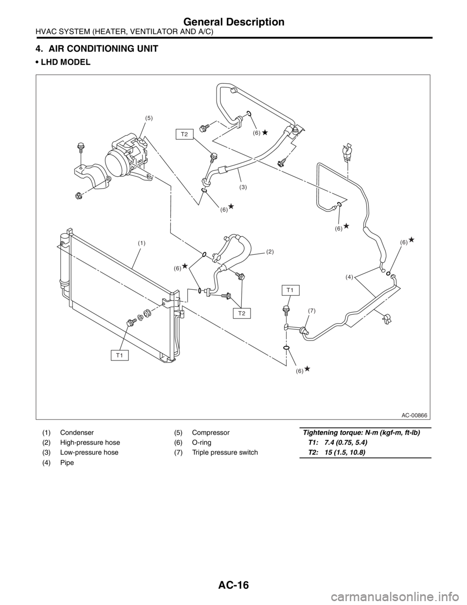
4. AIR CONDITIONING UNIT
LHD MODEL
(1) Condenser (5) CompressorTightening torque: N·m (kgf-m, ft-lb)
(2) High-pressure hose (6) O-ringT1: 7.4 (0.75, 5.4)
(3) Low-pressure hose (7) Triple pressure switchT2: 15 (1.5, 10.8)
(4) Pipe
AC-00866
(1)(3)
(4)
(7) (5)
(2)
T1
T1T2(6) (6)
(6)(6)
(6) T2(6)
Page 19 of 2870
AC-17
HVAC SYSTEM (HEATER, VENTILATOR AND A/C)
General Description
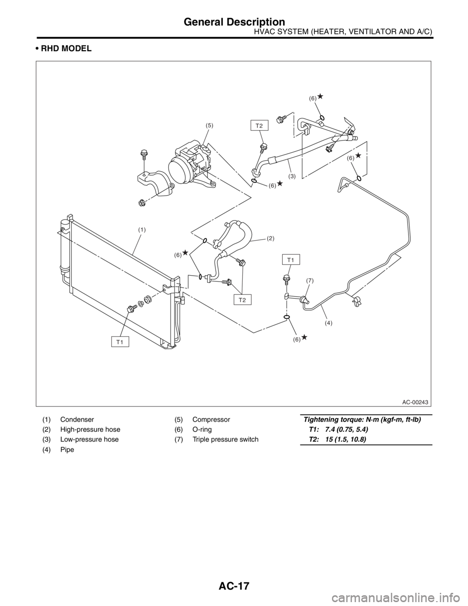
RHD MODEL
(1) Condenser (5) CompressorTightening torque: N·m (kgf-m, ft-lb)
(2) High-pressure hose (6) O-ringT1: 7.4 (0.75, 5.4)
(3) Low-pressure hose (7) Triple pressure switchT2: 15 (1.5, 10.8)
(4) Pipe
AC-00243
(1)(3)
(4)
(7)
(5)
(2)
T1
T1
T2
(6)
(6)
(6)
(6)
(6)
T2
Page 20 of 2870
AC-18
HVAC SYSTEM (HEATER, VENTILATOR AND A/C)
General Description
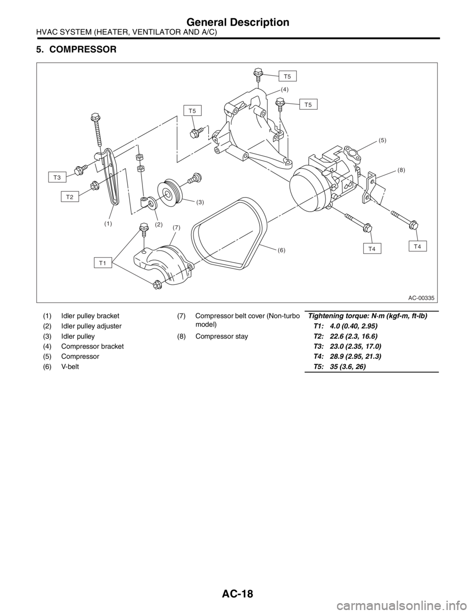
5. COMPRESSOR
(1) Idler pulley bracket (7) Compressor belt cover (Non-turbo
model)Tightening torque: N·m (kgf-m, ft-lb)
(2) Idler pulley adjusterT1: 4.0 (0.40, 2.95)
(3) Idler pulley (8) Compressor stayT2: 22.6 (2.3, 16.6)
(4) Compressor bracketT3: 23.0 (2.35, 17.0)
(5) CompressorT4: 28.9 (2.95, 21.3)
(6) V-beltT5: 35 (3.6, 26)
AC-00335
(1)
(3)
(2)
(4)
(5)
(8)
(6)
(7)
T3
T2
T1
T5
T5
T5
T4T4
Page 22 of 2870

AC-20
HVAC SYSTEM (HEATER, VENTILATOR AND A/C)
General Description
C: CAUTION
1. HFC-134a A/C SYSTEM
The cooling system components for the HFC-
134a system such as the refrigerant and compres-
sor oil are different from the old conventional HFC-
12 system components and they are incompatible
with each other.
Vehicles with the HFC-134a system can be iden-
tified by the label (A) attached to the vehicle.
Before maintenance, check which A/C system is in-
stalled in the vehicle.
2. COMPRESSOR OIL
HFC-134a compressor oil has no compatibility
with that for R12 system.
Use only the manufacturer-authorized compres-
sor oil for the HFC-134a system; only use
ZXL200PG.
Do not mix multiple compressor oils.
If HFC-12 compressor oil is used in a HFC-134a A/
C system, the compressor may become stuck due
to poor lubrication, or the refrigerant may leak due
to swelling of rubber parts.
On the other hand, if HFC-134a compressor oil is
used in a HFC-12 A/C system, the durability of the
A/C system will be lowered.
HFC-134a compressor oil is very hygroscopic.
When replacing or installing/removing A/C parts,
immediately isolate the oil from the atmosphere us-
ing a plug or tape. In order to avoid moisture, store
the oil in a container with its cap securely closed.
3. REFRIGERANT
The HFC-12 refrigerant cannot be used in the
HFC-134a A/C system. The HFC-134a refrigerant,
also, cannot be used in the HFC-12 A/C system.
If an incorrect or no refrigerant is used, poor lu-
brication will result and the compressor itself may
be damaged.
4. HANDLING OF REFRIGERANT
The refrigerant boils at approx. −30°C (−22°F).
When handling it, be sure to wear safety goggles
and protective gloves. Direct contact of the refriger-
ant with skin may cause frostbite.
If the refrigerant gets into your eye, avoid rubbing
your eyes with your hands. Wash your eye with
plenty of water, and receive medical treatment from
an eye doctor.
Do not heat a service can. If a service can is di-
rectly heated, or put into boiling water, the inside
pressure will become extremely high. This may
cause the can to explode. If a service can must be
warmed up, use hot water in 40°C (104°F) max.
Do not drop or impact a service can. (Observe
the precautions and operation procedure described
on the refrigerant can.)
When the engine is running, do not open the
high-pressure valve of the manifold gauge. The
high-pressure gas will back-flow resulting in an ex-
plosion of the can.
Provide good ventilation and do not work in a
closed area.
In order to prevent global warming, avoid releas-
ing HFC-134a into the atmosphere. Using a refrig-
erant recovery system, discharge and reuse it.
AC-00006
(A)
(A) Goggles
(B) Gloves
(C) Avoid open flame
(D) No direct heat on container
(E) Do not discharge
(F) Loosen
(A)
(B)
(C) (D)
(E) (F)
AC-00007
Page 23 of 2870
AC-21
HVAC SYSTEM (HEATER, VENTILATOR AND A/C)
General Description
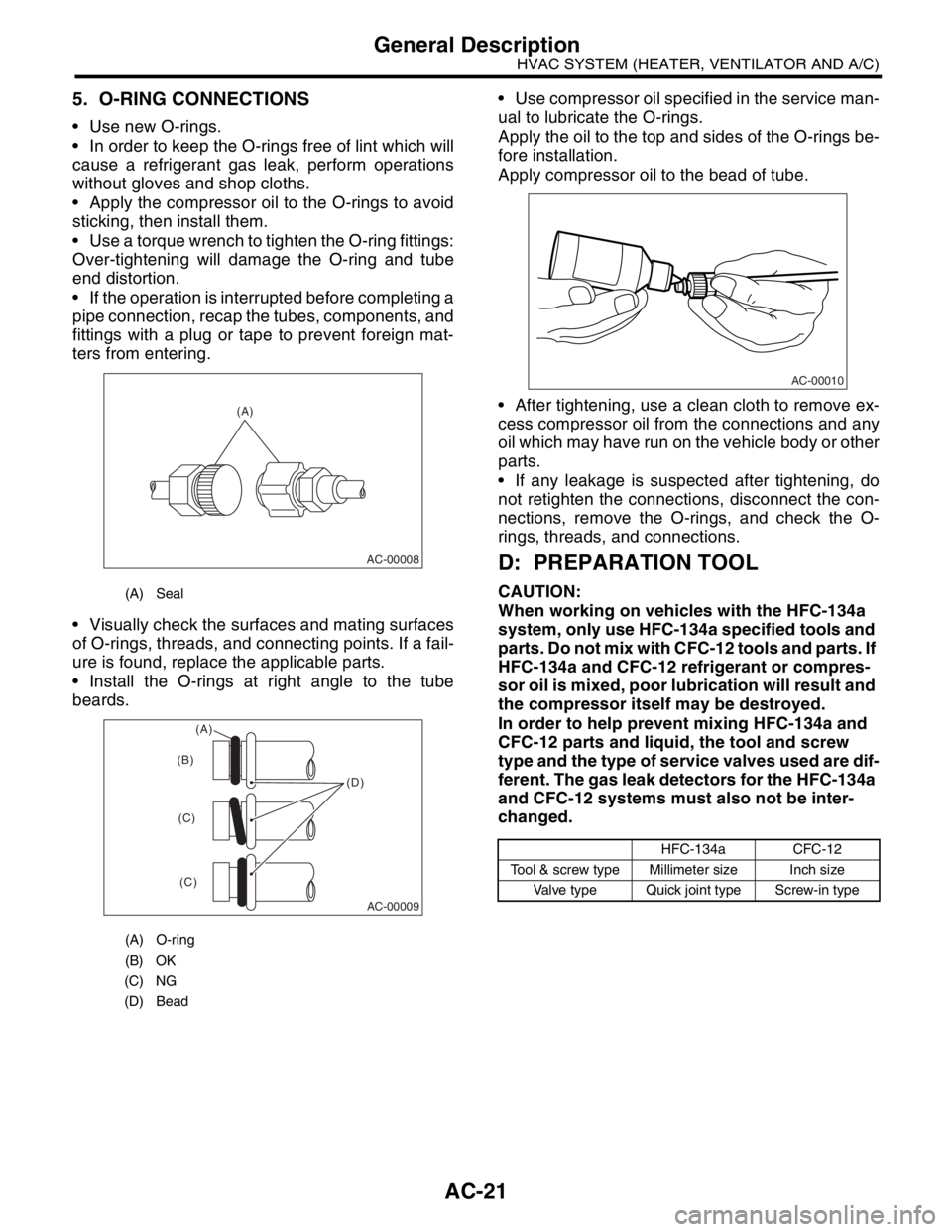
5. O-RING CONNECTIONS
Use new O-rings.
In order to keep the O-rings free of lint which will
cause a refrigerant gas leak, perform operations
without gloves and shop cloths.
Apply the compressor oil to the O-rings to avoid
sticking, then install them.
Use a torque wrench to tighten the O-ring fittings:
Over-tightening will damage the O-ring and tube
end distortion.
If the operation is interrupted before completing a
pipe connection, recap the tubes, components, and
fittings with a plug or tape to prevent foreign mat-
ters from entering.
Visually check the surfaces and mating surfaces
of O-rings, threads, and connecting points. If a fail-
ure is found, replace the applicable parts.
Install the O-rings at right angle to the tube
beards. Use compressor oil specified in the service man-
ual to lubricate the O-rings.
Apply the oil to the top and sides of the O-rings be-
fore installation.
Apply compressor oil to the bead of tube.
After tightening, use a clean cloth to remove ex-
cess compressor oil from the connections and any
oil which may have run on the vehicle body or other
parts.
If any leakage is suspected after tightening, do
not retighten the connections, disconnect the con-
nections, remove the O-rings, and check the O-
rings, threads, and connections.
D: PREPARATION TOOL
CAUTION:
When working on vehicles with the HFC-134a
system, only use HFC-134a specified tools and
parts. Do not mix with CFC-12 tools and parts. If
HFC-134a and CFC-12 refrigerant or compres-
sor oil is mixed, poor lubrication will result and
the compressor itself may be destroyed.
In order to help prevent mixing HFC-134a and
CFC-12 parts and liquid, the tool and screw
type and the type of service valves used are dif-
ferent. The gas leak detectors for the HFC-134a
and CFC-12 systems must also not be inter-
changed.(A) Seal
(A) O-ring
(B) OK
(C) NG
(D) Bead
(A)
AC-00008
AC-00009
(D) (B)
(C)
(C)
(A)
HFC-134a CFC-12
Tool & screw type Millimeter size Inch size
Valve type Quick joint type Screw-in type
AC-00010
Page 27 of 2870

AC-25
HVAC SYSTEM (HEATER, VENTILATOR AND A/C)
Refrigerant Pressure with Manifold Gauge Set
2. Refrigerant Pressure with Manifold Gauge Set
A: OPERATION
1) Place the vehicle in the shade and draftless condition.
2) Connect the manifold gauge set.
3) Open the front windows and close all doors.
4) Open the hood.
5) Increase the engine speed to 1,500 rpm.
6) Turn ON the A/C switch.
7) Turn the temperature control dial to MAX COOL.
8) Set the air inlet select switch to RECIRC position.
9) Turn the fan dial to HI.
10) Read the gauge.
Standard:
Low pressure: 127 — 196 kPa (1.3 — 2.0 kg/cm
2, 18 — 28 psi)
High pressure: 1,471 — 1, 667 kPa (15 — 17 kg/cm2, 213 — 242 psi)
Ambient temperature: 30 — 35
°C (86 — 95°F)
B: INSPECTION
Symptom Probable cause Repair order
High-pressure side is unusually high. Defective condenser fan motor
Clogged condenser fin
Too much refrigerant
Air inside the system
Defective receiver dryer Replace the fan motor.
Clean the condenser fin.
Discharge refrigerant.
Replace the receiver dryer.
After reevacuating the receiver dryer,
charge appropriate amount of refriger-
ant.
High-pressure side is unusually low. Defective compressor
Not enough refrigerant
Clogged expansion valve
Expansion valve frozen temporarily by
moisture Replace the compressor.
Check for leaks.
Replace the expansion valve.
Fully evacuate the expansion valve.
Low-pressure side is unusually high. Defective compressor
Defective expansion valve
Too much refrigerant Replace the compressor.
Replace the expansion valve.
Discharge refrigerant.
Low-pressure side is unusually low. Not enough refrigerant
Clogged expansion valve
Expansion valve frozen temporarily by
moisture
Saturated receiver dryer Check for leaks.
Replace the expansion valve.
Replace the receiver dryer.
Page 28 of 2870
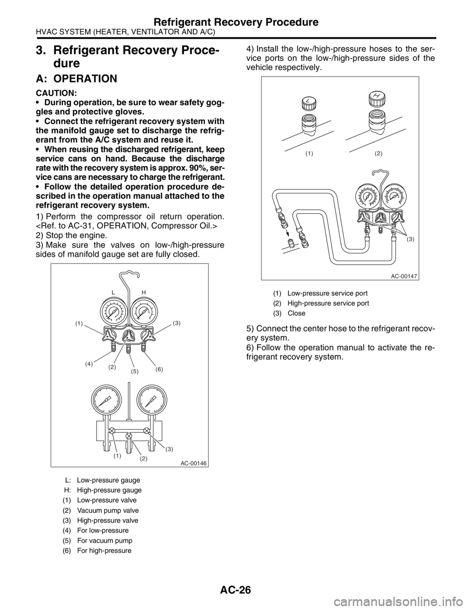
AC-26
HVAC SYSTEM (HEATER, VENTILATOR AND A/C)
Refrigerant Recovery Procedure
3. Refrigerant Recovery Proce-
dure
A: OPERATION
CAUTION:
During operation, be sure to wear safety gog-
gles and protective gloves.
Connect the refrigerant recovery system with
the manifold gauge set to discharge the refrig-
erant from the A/C system and reuse it.
When reusing the discharged refrigerant, keep
service cans on hand. Because the discharge
rate with the recovery system is approx. 90%, ser-
vice cans are necessary to charge the refrigerant.
Follow the detailed operation procedure de-
scribed in the operation manual attached to the
refrigerant recovery system.
1) Perform the compressor oil return operation.
2) Stop the engine.
3) Make sure the valves on low-/high-pressure
sides of manifold gauge set are fully closed.4) Install the low-/high-pressure hoses to the ser-
vice ports on the low-/high-pressure sides of the
vehicle respectively.
5) Connect the center hose to the refrigerant recov-
ery system.
6) Follow the operation manual to activate the re-
frigerant recovery system.
L: Low-pressure gauge
H: High-pressure gauge
(1) Low-pressure valve
(2) Vacuum pump valve
(3) High-pressure valve
(4) For low-pressure
(5) For vacuum pump
(6) For high-pressure
AC-00146
(2) (4)
(5)(6)
(3)(3)
(2) (1)H L
(1)
(1) Low-pressure service port
(2) High-pressure service port
(3) Close
AC-00147
(3) (2) (1)