Removal SUBARU FORESTER 2004 Service Repair Manual
[x] Cancel search | Manufacturer: SUBARU, Model Year: 2004, Model line: FORESTER, Model: SUBARU FORESTER 2004Pages: 2870, PDF Size: 38.67 MB
Page 2856 of 2870
CL-30
CLUTCH SYSTEM
Clutch Pipe and Hose
B: INSTALLATION
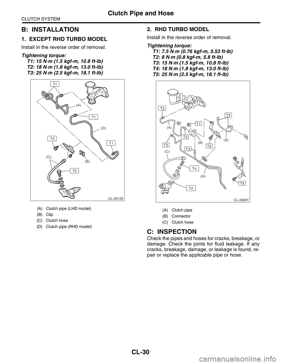
1. EXCEPT RHD TURBO MODEL
Install in the reverse order of removal.
Tightening torque:
T1: 15 N
⋅m (1.5 kgf-m, 10.8 ft-lb)
T2: 18 N
⋅m (1.8 kgf-m, 13.0 ft-lb)
T3: 25 N
⋅m (2.5 kgf-m, 18.1 ft-lb)
2. RHD TURBO MODEL
Install in the reverse order of removal.
Tightening torque:
T1: 7.5 N
⋅m (0.76 kgf-m, 5.53 ft-lb)
T2: 8 N
⋅m (0.8 kgf-m, 5.8 ft-lb)
T3: 15 N
⋅m (1.5 kgf-m, 10.8 ft-lb)
T4: 18 N
⋅m (1.8 kgf-m, 13.0 ft-lb)
T5: 25 N
⋅m (2.5 kgf-m, 18.1 ft-lb)
C: INSPECTION
Check the pipes and hoses for cracks, breakage, or
damage. Check the joints for fluid leakage. If any
cracks, breakage, damage, or leakage is found, re-
pair or replace the applicable pipe or hose.
(A) Clutch pipe (LHD model)
(B) Clip
(C) Clutch hose
(D) Clutch pipe (RHD model)
(D)
(B) (C)(A)
T1
T1
T2
T1
T3
CL-00125
(A) Clutch pipe
(B) Connector
(C) Clutch hose
(A)
(A) (A)
T3
T3T3
T3
T1
T3
T5
T5
(C)
T2
T4
(B)
CL-00061
Page 2858 of 2870
CL-32
CLUTCH SYSTEM
Clutch Fluid Air Bleeding
9. Clutch Fluid Air Bleeding
A: PROCEDURE
1. NON-TURBO MODEL
NOTE:
Bleed air from the oil line with help of co-worker.
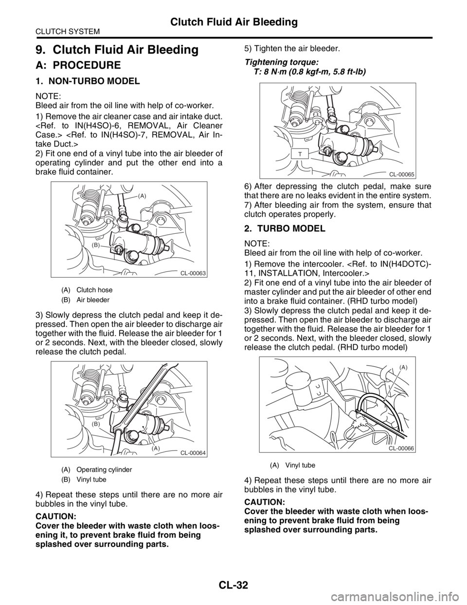
1) Remove the air cleaner case and air intake duct.
2) Fit one end of a vinyl tube into the air bleeder of
operating cylinder and put the other end into a
brake fluid container.
3) Slowly depress the clutch pedal and keep it de-
pressed. Then open the air bleeder to discharge air
together with the fluid. Release the air bleeder for 1
or 2 seconds. Next, with the bleeder closed, slowly
release the clutch pedal.
4) Repeat these steps until there are no more air
bubbles in the vinyl tube.
CAUTION:
Cover the bleeder with waste cloth when loos-
ening it, to prevent brake fluid from being
splashed over surrounding parts.5) Tighten the air bleeder.
Tightening torque:
T: 8 N
⋅m (0.8 kgf-m, 5.8 ft-lb)
6) After depressing the clutch pedal, make sure
that there are no leaks evident in the entire system.
7) After bleeding air from the system, ensure that
clutch operates properly.
2. TURBO MODEL
NOTE:
Bleed air from the oil line with help of co-worker.
1) Remove the intercooler.
2) Fit one end of a vinyl tube into the air bleeder of
master cylinder and put the air bleeder of other end
into a brake fluid container. (RHD turbo model)
3) Slowly depress the clutch pedal and keep it de-
pressed. Then open the air bleeder to discharge air
together with the fluid. Release the air bleeder for 1
or 2 seconds. Next, with the bleeder closed, slowly
release the clutch pedal. (RHD turbo model)
4) Repeat these steps until there are no more air
bubbles in the vinyl tube.
CAUTION:
Cover the bleeder with waste cloth when loos-
ening to prevent brake fluid from being
splashed over surrounding parts.
(A) Clutch hose
(B) Air bleeder
(A) Operating cylinder
(B) Vinyl tube
CL-00063
(B)(A)
CL-00064
(B)
(A)
(A) Vinyl tube
CL-00065
T
(A)
CL-00066
Page 2860 of 2870
CL-34
CLUTCH SYSTEM
Clutch Pedal
10.Clutch Pedal
A: REMOVAL
1. LHD MODEL
1) Remove the steering column.
2) Disconnect the connectors from stop light switch
and clutch switch.
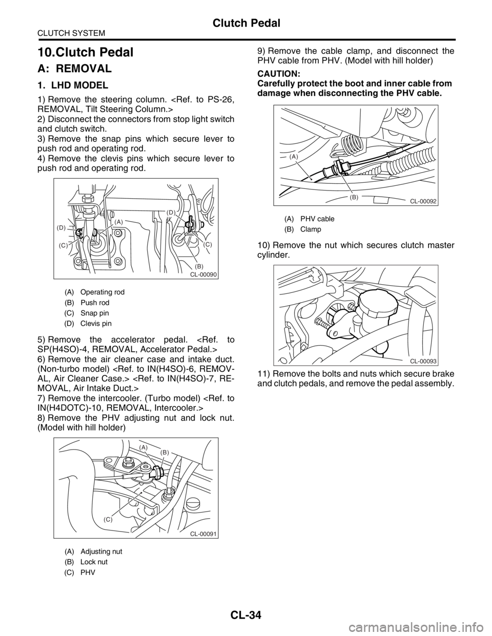
3) Remove the snap pins which secure lever to
push rod and operating rod.
4) Remove the clevis pins which secure lever to
push rod and operating rod.
5) Remove the accelerator pedal.
6) Remove the air cleaner case and intake duct.
(Non-turbo model)
7) Remove the intercooler. (Turbo model)
8) Remove the PHV adjusting nut and lock nut.
(Model with hill holder)9) Remove the cable clamp, and disconnect the
PHV cable from PHV. (Model with hill holder)
CAUTION:
Carefully protect the boot and inner cable from
damage when disconnecting the PHV cable.
10) Remove the nut which secures clutch master
cylinder.
11) Remove the bolts and nuts which secure brake
and clutch pedals, and remove the pedal assembly.
(A) Operating rod
(B) Push rod
(C) Snap pin
(D) Clevis pin
(A) Adjusting nut
(B) Lock nut
(C) PHV
(D)
(B)(C)
(C) (D)(A)
CL-00090
CL-00091
(C)(B) (A)
(A) PHV cable
(B) Clamp
(B) (A)
CL-00092
CL-00093
Page 2865 of 2870
CL-39
CLUTCH SYSTEM
Clutch Pedal
9) Tighten the push rod lock nut.
Tightening torque :
10 N
⋅m (1.0 kgf-m, 7.2 ft-lb)
10) Measure the full stroke amount of clutch pedal
again.
Specified clutch pedal full stroke: A
130 — 135 mm (5.12 — 5.31 in)
11) Install the clutch switch.
2. RHD MODEL
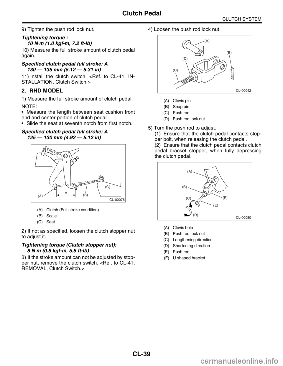
1) Measure the full stroke amount of clutch pedal.
NOTE:
Measure the length between seat cushion front
end and center portion of clutch pedal.
Slide the seat at seventh notch from first notch.
Specified clutch pedal full stroke: A
125 — 130 mm (4.92 — 5.12 in)
2) If not as specified, loosen the clutch stopper nut
to adjust it.
Tightening torque (Clutch stopper nut):
8 N
⋅m (0.8 kgf-m, 5.8 ft-lb)
3) If the stroke amount can not be adjusted by stop-
per nut, remove the clutch switch.
5) Turn the push rod to adjust.
(1) Ensure that the clutch pedal contacts stop-
per bolt, when releasing the clutch pedal.
(2) Ensure that the clutch pedal contacts clutch
pedal bracket stopper, when fully depressing
the clutch pedal.
(A) Clutch (Full stroke condition)
(B) Scale
(C) Seat
CL-00078(A)(B)(C)A
(A) Clevis pin
(B) Snap pin
(C) Push rod
(D) Push rod lock nut
(A) Clevis hole
(B) Push rod lock nut
(C) Lengthening direction
(D) Shortening direction
(E) Push rod
(F) U shaped bracket
CL-00042
(A)
(B)
(C)(D)
CL-00080
(B)(A)
(C)
(D)(E)(F)
Page 2867 of 2870
CL-41
CLUTCH SYSTEM
Clutch Switch
11.Clutch Switch
A: REMOVAL
1) Disconnect the ground cable from battery.
2) Remove the instrument panel lower cover.
3) Disconnect the connector from clutch switch.
4) Remove the clutch switch.
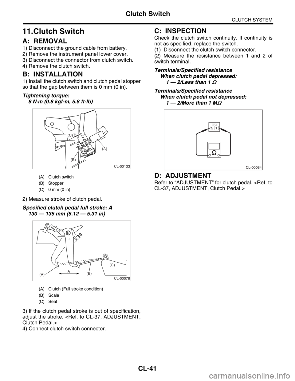
B: INSTALLATION
1) Install the clutch switch and clutch pedal stopper
so that the gap between them is 0 mm (0 in).
Tightening torque:
8 N
⋅m (0.8 kgf-m, 5.8 ft-lb)
2) Measure stroke of clutch pedal.
Specified clutch pedal full stroke: A
130 — 135 mm (5.12 — 5.31 in)
3) If the clutch pedal stroke is out of specification,
adjust the stroke.
4) Connect clutch switch connector.
C: INSPECTION
Check the clutch switch continuity. If continuity is
not as specified, replace the switch.
(1) Disconnect the clutch switch connector.
(2) Measure the resistance between 1 and 2 of
switch terminal.
Terminals/Specified resistance
When clutch pedal depressed:
1 — 2/Less than 1
Ω
Terminals/Specified resistance
When clutch pedal not depressed:
1 — 2/More than 1 M
Ω
D: ADJUSTMENT
Refer to “ADJUSTMENT” for clutch pedal.
(A) Clutch switch
(B) Stopper
(C) 0 mm (0 in)
(A) Clutch (Full stroke condition)
(B) Scale
(C) Seat
(A)
(B) (C)
CL-00133
CL-00078(A)(B)(C)A
CL-00084
21