Manual transmission removal SUBARU FORESTER 2004 Service Repair Manual
[x] Cancel search | Manufacturer: SUBARU, Model Year: 2004, Model line: FORESTER, Model: SUBARU FORESTER 2004Pages: 2870, PDF Size: 38.67 MB
Page 687 of 2870
HU-4
HOW TO USE THIS MANUAL
How to Use This Manual
4. SPECIFICATION
If necessary, specifications are also included.
5. INSPECTION
Inspections are included to be carried out before and after maintenance.
6. MAINTENANCE
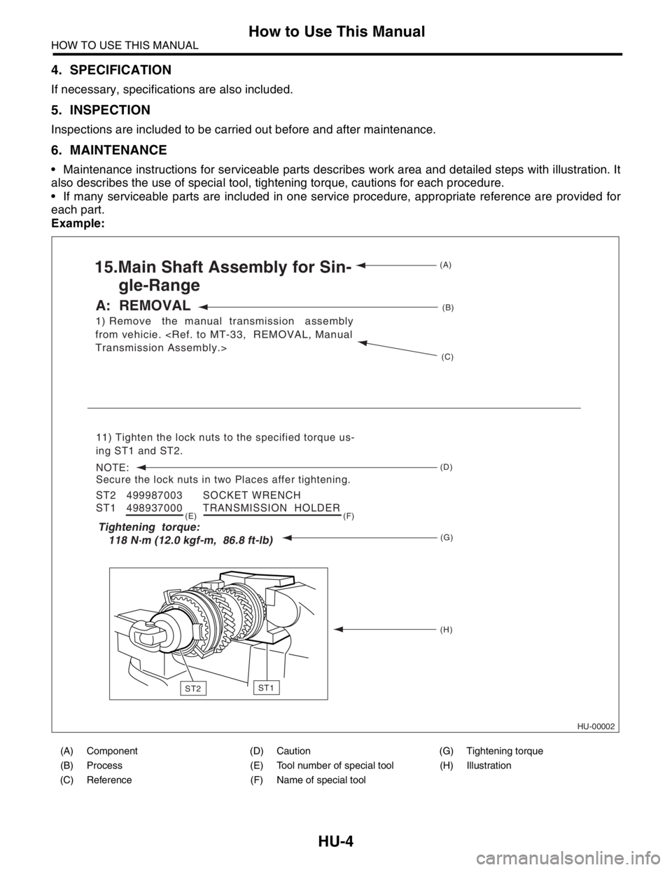
• Maintenance instructions for serviceable parts describes work area and detailed steps with illustration. It
also describes the use of special tool, tightening torque, cautions for each procedure.
If many serviceable parts are included in one service procedure, appropriate reference are provided for
each part.
Example:
(A) Component (D) Caution (G) Tightening torque
(B) Process (E) Tool number of special tool (H) Illustration
(C) Reference (F) Name of special tool
HU-00002
1) Remove the manual transmission assembly
from vehicie.
15.Main Shaft Assembly for Sin-
gle-Range
A: REMOVAL
11) Tighten the lock nuts to the specified torque us-
ing ST1 and ST2.
NOTE:
Secure the lock nuts in two Places affer tightening.
ST2 499987003 SOCKET WRENCH
ST1 498937000 TRANSMISSION HOLDER
(A)
(B)
(C)
(D)
(G) (E) (F)
(H)
Tightening torque:
118 N m (12.0 kgf-m, 86.8 ft-lb)
ST1ST2
Page 2456 of 2870
4AT-142
AUTOMATIC TRANSMISSION
Transmission Control Device
39.Transmission Control Device
A: REMOVAL
1) Remove the transmission assembly from vehi-
cle.
2) Pull out the torque converter clutch assembly.
3) Remove the input shaft.
4) Lift-up the lever on rear side of transmission har-
ness connector, and then disconnect it from the
stay.
5) Disconnect the air breather hose.
6) Disconnect the inhibitor switch connector from
the stay.
7) Wrap vinyl tape around the nipple attached to
the air breather hose.
8) Remove the pitching stopper bracket.
9) Remove the inhibitor switch.
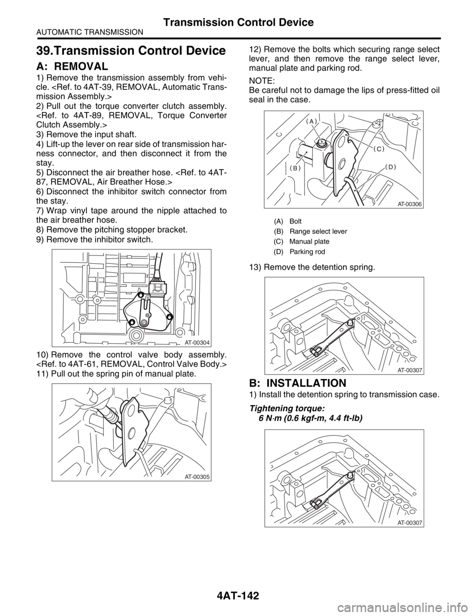
10) Remove the control valve body assembly.
11) Pull out the spring pin of manual plate.12) Remove the bolts which securing range select
lever, and then remove the range select lever,
manual plate and parking rod.
NOTE:
Be careful not to damage the lips of press-fitted oil
seal in the case.
13) Remove the detention spring.
B: INSTALLATION
1) Install the detention spring to transmission case.
Tightening torque:
6 N
⋅m (0.6 kgf-m, 4.4 ft-lb)
AT-00304
AT-00305
(A) Bolt
(B) Range select lever
(C) Manual plate
(D) Parking rod
AT-00306
AT-00307
AT-00307
Page 2729 of 2870

5MT-17
MANUAL TRANSMISSION AND DIFFERENTIAL
General Description
C: CAUTION
Wear working clothing, including a cap, protec-
tive goggles, and protective shoes during opera-
tion.
Remove contamination including dirt and corro-
sion before removal, installation, and disassembly.
Keep the disassembled parts in order and pro-
tect them from dust or dirt.
Until the oil pan is removed, do not place with the
oil pan side facing up to prevent foreign matter from
entering the valve body.
Before removal, installation or disassembly, be
sure to clarify the failure. Avoid unnecessary re-
moval, installation, disassembly and replacement.
When disassembling the case and other light al-
loy parts, use a plastic hammer to force it apart. Do
not pry it apart with a screwdriver or other tool.
Be careful not to burn your hands, because each
part on the vehicle is hot after running. Use SUBARU genuine gear oil, grease etc. or
the equivalent. Do not mix gear oil, grease etc. with
that of another grade or from other manufacturers.
Be sure to tighten fasteners including bolts and
nuts to the specified torque.
Place shop jacks or rigid racks at the specified
points.
Apply gear oil onto sliding or revolution surfaces
before installation.
Replace deformed or otherwise damaged snap
rings with new ones.
Before installing O-rings or oil seals, apply suffi-
cient amount of gear oil to avoid damage and defor-
mation.
Be careful not to incorrectly install or fail to install
O-rings, snap rings and other such parts.
Before securing a part on a vise, place cushion-
ing material such as wood blocks, aluminum plate,
or shop cloth between the part and the vis e.
Avoid damaging the mating surface of the case.
Before applying sealant, completely remove the
old seal.
D: PREPARATION TOOL
1. SPECIAL TOOL
ILLUSTRATION TOOL NUMBER DESCRIPTION REMARKS
399411700 ACCENT BALL
INSTALLERUsed for installing reverse shifter rail arm.
899524100 PULLER SET Used for removing and installing roller bearing
(Differential).
(1) PULLER
(2) CAP
ST-399411700
ST-899524100
Page 2744 of 2870
5MT-32
MANUAL TRANSMISSION AND DIFFERENTIAL
Manual Transmission Assembly
3. Manual Transmission As-
sembly
A: REMOVAL
1) Set the vehicle on a lift.
2) Disconnect the ground cable from battery.
3) Drain the transmission gear oil completely.
Oil.>
4) Open the front hood fully, and support with stay.
5) Remove the air intake duct and air cleaner case.
(Non-turbo model)
6) Remove the air cleaner case stay. (Non-turbo
model)
7) Remove the intercooler. (Turbo model)
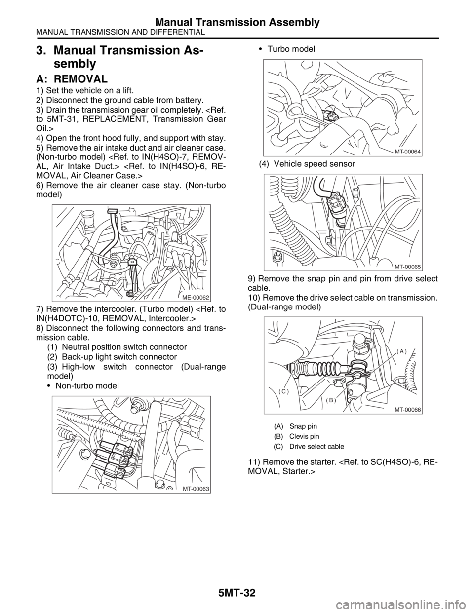
8) Disconnect the following connectors and trans-
mission cable.
(1) Neutral position switch connector
(2) Back-up light switch connector
(3) High-low switch connector (Dual-range
model)
Non-turbo model Turbo model
(4) Vehicle speed sensor
9) Remove the snap pin and pin from drive select
cable.
10) Remove the drive select cable on transmission.
(Dual-range model)
11) Remove the starter.
ME-00062
MT-00063
(A) Snap pin
(B) Clevis pin
(C) Drive select cable
MT-00064
MT-00065
MT-00066
(A)
(B)
(C)
Page 2746 of 2870
5MT-34
MANUAL TRANSMISSION AND DIFFERENTIAL
Manual Transmission Assembly
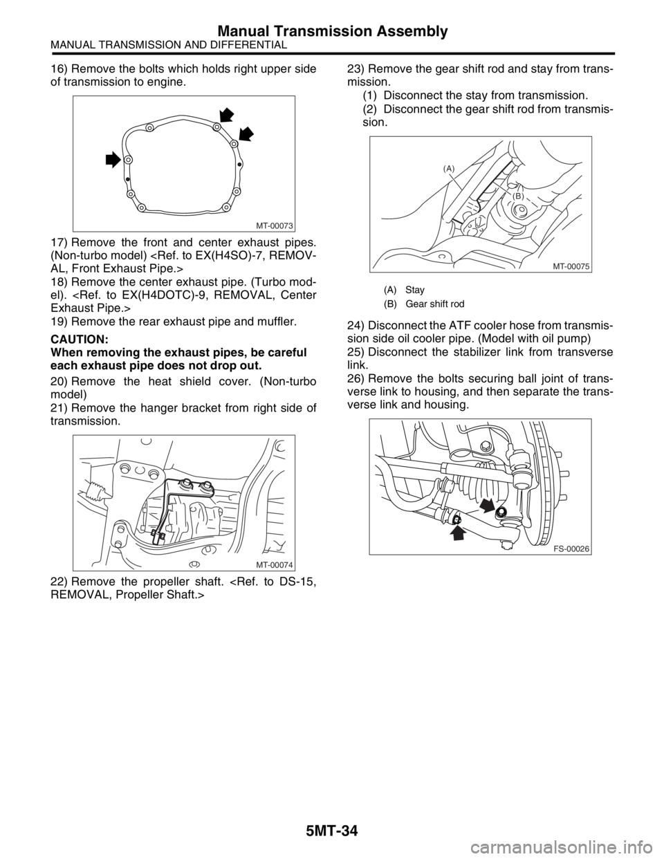
16) Remove the bolts which holds right upper side
of transmission to engine.
17) Remove the front and center exhaust pipes.
(Non-turbo model)
18) Remove the center exhaust pipe. (Turbo mod-
el).
19) Remove the rear exhaust pipe and muffler.
CAUTION:
When removing the exhaust pipes, be careful
each exhaust pipe does not drop out.
20) Remove the heat shield cover. (Non-turbo
model)
21) Remove the hanger bracket from right side of
transmission.
22) Remove the propeller shaft.
mission.
(1) Disconnect the stay from transmission.
(2) Disconnect the gear shift rod from transmis-
sion.
24) Disconnect the ATF cooler hose from transmis-
sion side oil cooler pipe. (Model with oil pump)
25) Disconnect the stabilizer link from transverse
link.
26) Remove the bolts securing ball joint of trans-
verse link to housing, and then separate the trans-
verse link and housing.
MT-00073
MT-00074
(A) Stay
(B) Gear shift rod
MT-00075
(A)
(B)
(B)
FS-00026
Page 2751 of 2870
5MT-39
MANUAL TRANSMISSION AND DIFFERENTIAL
Transmission Mounting System
4. Transmission Mounting Sys-
tem
A: REMOVAL
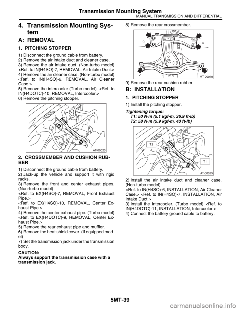
1. PITCHING STOPPER
1) Disconnect the ground cable from battery.
2) Remove the air intake duct and cleaner case.
3) Remove the air intake duct. (Non-turbo model)
4) Remove the air cleaner case. (Non-turbo model)
5) Remove the intercooler (Turbo model).
6) Remove the pitching stopper.
2. CROSSMEMBER AND CUSHION RUB-
BER
1) Disconnect the ground cable from battery.
2) Jack-up the vehicle and support it with rigid
racks.
3) Remove the front and center exhaust pipes.
(Non-turbo model)
4) Remove the center exhaust pipe. (Turbo model)
5) Remove the rear exhaust pipe and muffler.
6) Remove the heat shield cover. (If equipped mod-
el)
7) Set the transmission jack under the transmission
body.
CAUTION:
Always support the transmission case with a
transmission jack. 8) Remove the rear crossmember.
9) Remove the rear cushion rubber.
B: INSTALLATION
1. PITCHING STOPPER
1) Install the pitching stopper.
Tightening torque:
T1: 50 N·m (5.1 kgf-m, 36.9 ft-lb)
T2: 58 N·m (5.9 kgf-m, 43 ft-lb)
2) Install the air intake duct and cleaner case.
(Non-turbo model)
3) Install the intercooler. (Turbo model)
4) Connect the battery ground cable to battery.
AT-00023
MT-00079
AT-00025
T1
T2
Page 2754 of 2870
5MT-42
MANUAL TRANSMISSION AND DIFFERENTIAL
Differential Side Retainer Oil Seal
6. Differential Side Retainer Oil
Seal
A: INSPECTION
Check the differential side retainer oil seal for leak-
age of gear oil. If oil leaks, replace the oil seal.
B: REPLACEMENT
1) Lift-up the vehicle.
2) Drain the gear oil from oil drain plug.
3) Replace the gasket with new one, and then tight-
en the differential oil drain plug.
Tightening torque:
44 N·m (4.5 kgf-m, 32.5 ft-lb) (Aluminum gas-
ket)
70 N·m (7.1 kgf-m, 51.6 ft-lb) (Copper gasket)
4) Remove the front exhaust pipe and center ex-
haust pipe. (Non-turbo model)
5) Separate the front drive shaft from transmission.
6) Using a vinyl tape, etc. wrapped flat tip screw-
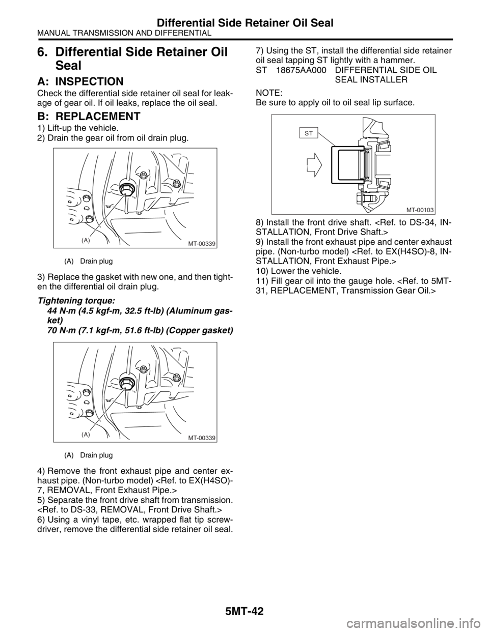
driver, remove the differential side retainer oil seal.7) Using the ST, install the differential side retainer
oil seal tapping ST lightly with a hammer.
ST 18675AA000 DIFFERENTIAL SIDE OIL
SEAL INSTALLER
NOTE:
Be sure to apply oil to oil seal lip surface.
8) Install the front drive shaft.
9) Install the front exhaust pipe and center exhaust
pipe. (Non-turbo model)
10) Lower the vehicle.
11) Fill gear oil into the gauge hole.
(A) Drain plug
(A) Drain plug
(A)
MT-00339
(A)
MT-00339
MT-00103
ST
Page 2755 of 2870
5MT-43
MANUAL TRANSMISSION AND DIFFERENTIAL
Switches and Harness
7. Switches and Harness
A: REMOVAL
1. BACK-UP LIGHT AND NEUTRAL POSI-
TION SWITCH
1) Disconnect the ground cable from battery.
2) Remove the air intake duct and cleaner case.
3) Remove the intercooler (Turbo model).
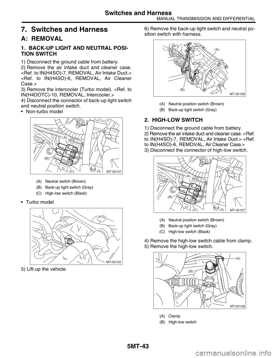
4) Disconnect the connector of back-up light switch
and neutral position switch.
Non-turbo model
Turbo model
5) Lift-up the vehicle.6) Remove the back-up light switch and neutral po-
sition switch with harness.
2. HIGH-LOW SWITCH
1) Disconnect the ground cable from battery.
2) Remove the air intake duct and cleaner case.
3) Disconnect the connector of high-low switch.
4) Remove the high-low switch cable from clamp.
5) Remove the high-low switch.
(A) Neutral switch (Brown)
(B) Back-up light switch (Gray)
(C) High-low switch (Black)
MT-00107
(B)
(C)
(A)
MT-00105
(A) Neutral position switch (Brown)
(B) Back-up light switch (Gray)
(A) Neutral position switch (Brown)
(B) Back-up light switch (Gray)
(C) High-low switch (Black)
(A) Clamp
(B) High-low switch
MT-00106
(A)
(B)
MT-00107
(B)
(C)
(A)
MT-00108
(B)(A)
Page 2758 of 2870
5MT-46
MANUAL TRANSMISSION AND DIFFERENTIAL
Vehicle Speed Sensor
8. Vehicle Speed Sensor
A: REMOVAL
1) Disconnect the ground cable from battery.
2) Lift-up the vehicle.
3) Remove the front, center and rear exhaust pipe
and muffler.
4) Disconnect the connector from vehicle speed
sensor.
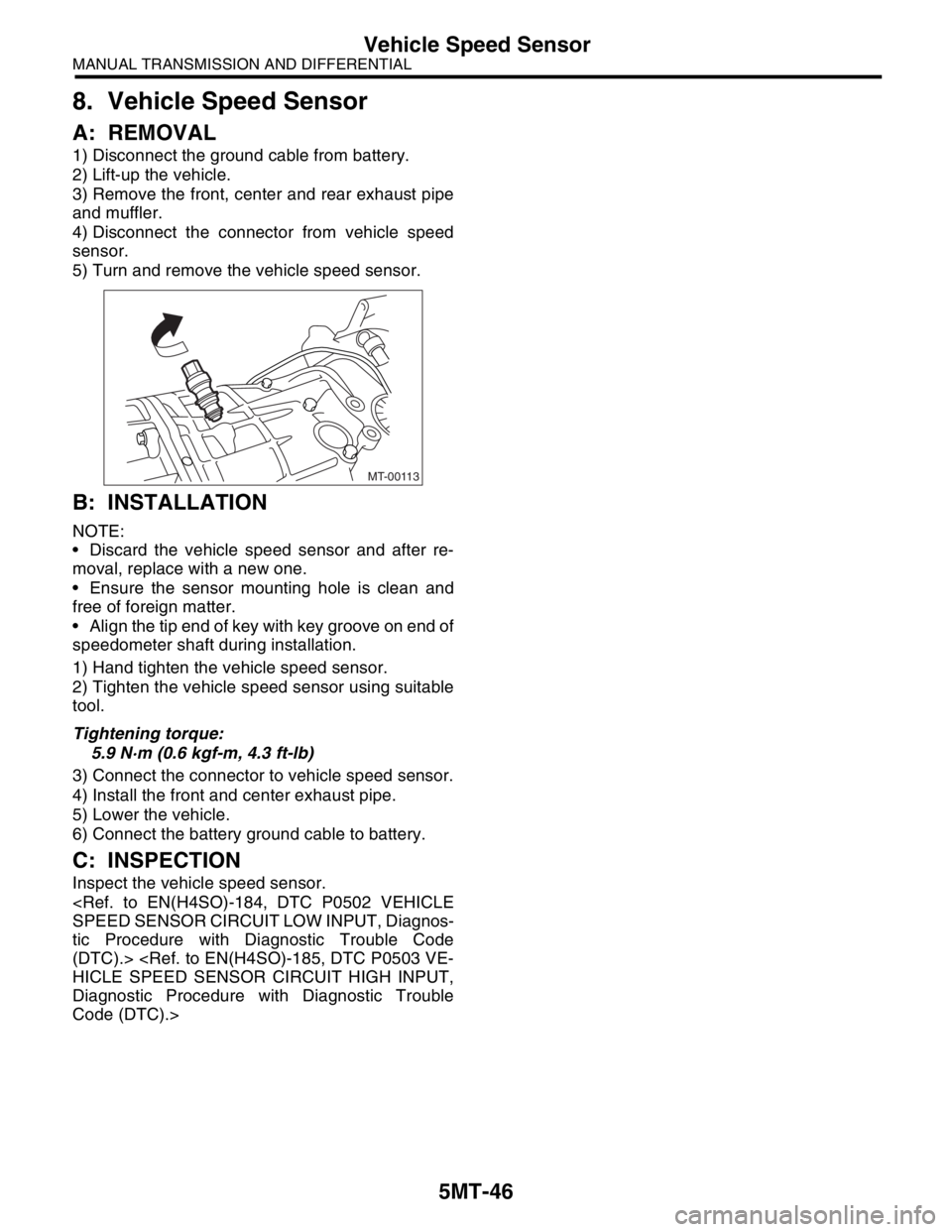
5) Turn and remove the vehicle speed sensor.
B: INSTALLATION
NOTE:
Discard the vehicle speed sensor and after re-
moval, replace with a new one.
Ensure the sensor mounting hole is clean and
free of foreign matter.
Align the tip end of key with key groove on end of
speedometer shaft during installation.
1) Hand tighten the vehicle speed sensor.
2) Tighten the vehicle speed sensor using suitable
tool.
Tightening torque:
5.9 N·m (0.6 kgf-m, 4.3 ft-lb)
3) Connect the connector to vehicle speed sensor.
4) Install the front and center exhaust pipe.
5) Lower the vehicle.
6) Connect the battery ground cable to battery.
C: INSPECTION
Inspect the vehicle speed sensor.
tic Procedure with Diagnostic Trouble Code
(DTC).>
Diagnostic Procedure with Diagnostic Trouble
Code (DTC).>
MT-00113
Page 2760 of 2870
5MT-48
MANUAL TRANSMISSION AND DIFFERENTIAL
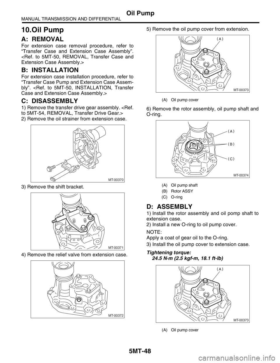
Oil Pump
10.Oil Pump
A: REMOVAL
For extension case removal procedure, refer to
“Transfer Case and Extension Case Assembly”.
B: INSTALLATION
For extension case installation procedure, refer to
“Transfer Case Pump and Extension Case Assem-
bly”.
C: DISASSEMBLY
1) Remove the transfer drive gear assembly.
2) Remove the oil strainer from extension case.
3) Remove the shift bracket.
4) Remove the relief valve from extension case.5) Remove the oil pump cover from extension.
6) Remove the rotor assembly, oil pump shaft and
O-ring.
D: ASSEMBLY
1) Install the rotor assembly and oil pomp shaft to
extension case.
2) Install a new O-ring to oil pump cover.
NOTE:
Apply a coat of gear oil to the O-ring.
3) Install the oil pump cover to extension case.
Tightening torque:
24.5 N·m (2.5 kgf-m, 18.1 ft-lb)
MT-00370
MT-00371
MT-00372
(A) Oil pump cover
(A) Oil pump shaft
(B) Rotor ASSY
(C) O-ring
(A) Oil pump cover
MT-00373
MT-00374
MT-00373