drain bolt SUBARU FORESTER 2004 Service Repair Manual
[x] Cancel search | Manufacturer: SUBARU, Model Year: 2004, Model line: FORESTER, Model: SUBARU FORESTER 2004Pages: 2870, PDF Size: 38.67 MB
Page 41 of 2870
AC-39
HVAC SYSTEM (HEATER, VENTILATOR AND A/C)
Heater Cooling Unit
14.Heater Cooling Unit
A: REMOVAL
1) Disconnect the ground cable from battery.
2) Using the refrigerant recovery system, dis-
charge refrigerant.
3) Drain the engine coolant from radiator.
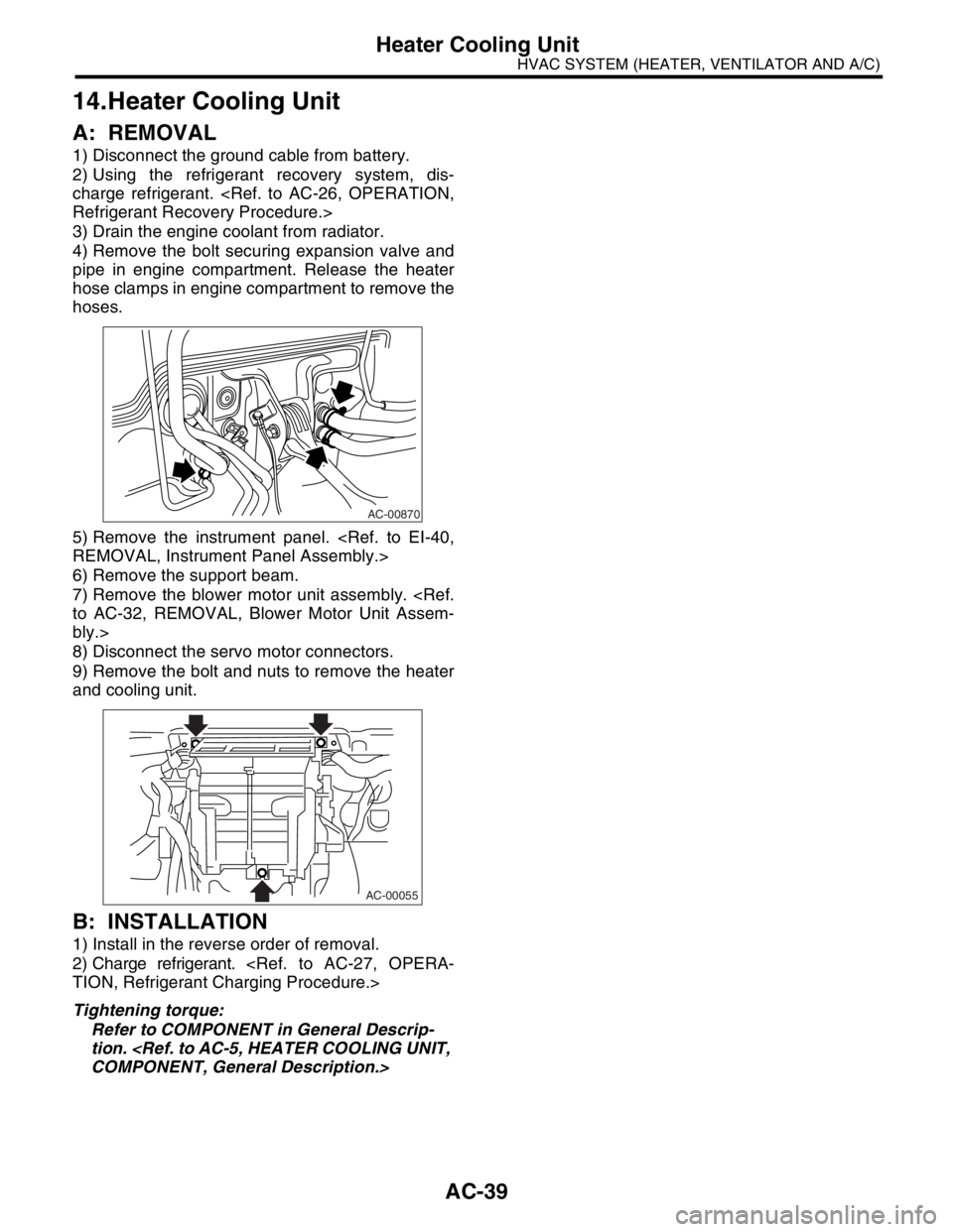
4) Remove the bolt securing expansion valve and
pipe in engine compartment. Release the heater
hose clamps in engine compartment to remove the
hoses.
5) Remove the instrument panel.
6) Remove the support beam.
7) Remove the blower motor unit assembly.
bly.>
8) Disconnect the servo motor connectors.
9) Remove the bolt and nuts to remove the heater
and cooling unit.
B: INSTALLATION
1) Install in the reverse order of removal.
2) Charge refrigerant.
Tightening torque:
Refer to COMPONENT in General Descrip-
tion.
AC-00870
AC-00055
Page 51 of 2870
AC-49
HVAC SYSTEM (HEATER, VENTILATOR AND A/C)
Heater Cock Solenoid Valve
24.Heater Cock Solenoid Valve
A: REMOVAL
1) Drain the engine coolant.
2) Remove the battery.
3) Remove the two bolts and disconnect harness
connector, and move the washer tank forward.
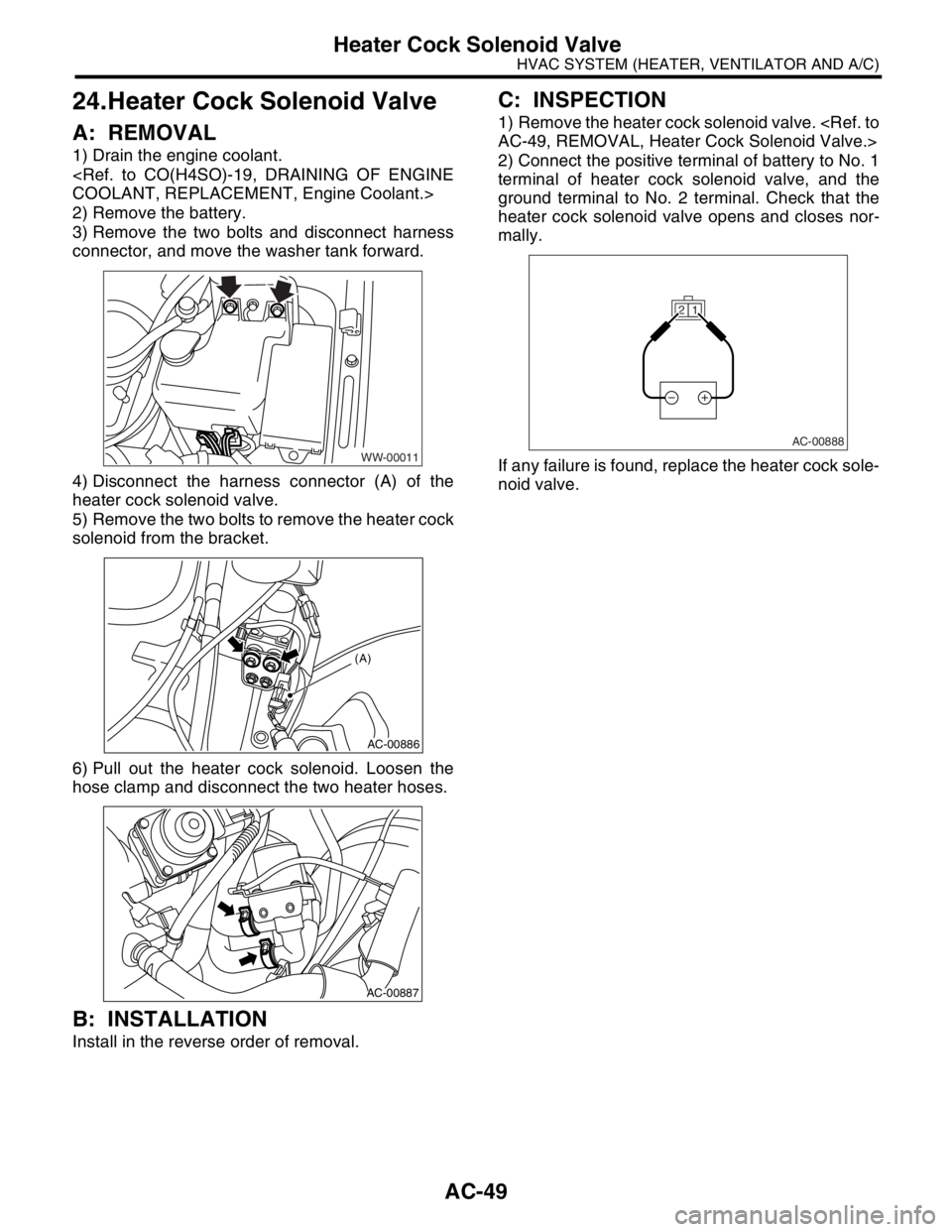
4) Disconnect the harness connector (A) of the
heater cock solenoid valve.
5) Remove the two bolts to remove the heater cock
solenoid from the bracket.
6) Pull out the heater cock solenoid. Loosen the
hose clamp and disconnect the two heater hoses.
B: INSTALLATION
Install in the reverse order of removal.
C: INSPECTION
1) Remove the heater cock solenoid valve.
2) Connect the positive terminal of battery to No. 1
terminal of heater cock solenoid valve, and the
ground terminal to No. 2 terminal. Check that the
heater cock solenoid valve opens and closes nor-
mally.
If any failure is found, replace the heater cock sole-
noid valve.
WW-00011
AC-00886
(A)
AC-00887
1 2
AC-00888
Page 470 of 2870

SR-6
SUNROOF/T-TOP/CONVERTIBLE TOP (SUNROOF)
Sunroof Assembly
4. Sunroof Assembly
A: REMOVAL
1) Disconnect the ground cable from battery.
2) Remove roof trim.
3) Remove sunroof lid.
4) Disconnect the four drain tubes (A) from sunroof
frame.
5) Disconnect sunroof harness connector.
6) Remove the bolts, and then remove the frame
bracket.
7) Remove bolts and nuts and then detach sunroof
frame.
B: INSTALLATION
Install in the reverse order of removal.
CAUTION:
Be careful not to snag harness.
NOTE:
Make sure to connect harness connector.
When installing drain tube, insert it securely into
drain pipe.
Length A:
15 mm (0.59 in) or more
C: DISASSEMBLY
1) Remove sunroof frame.
2) Cut the pawl (A) of front sunshade RH.
3) Remove the front slider RH.
4) Pull out the sunshade (B) from sunroof frame.
D: ASSEMBLY
Assemble in the reverse order of disassembly.
SR-00014
SR-00015(A)(A)
SR-00005
A
SR-00006
(A)
SR-00007
Page 779 of 2870
PM-42
PERIODIC MAINTENANCE SERVICE
Steering System (Power Steering)
(2) Retighten the adjusting screw to 7.4 N·m
(0.75 kgf-m, 5.4 ft-lb) and back off 25°.
(3) Apply Liquid gasket to at least 1/3 of entire
perimeter of adjusting screw thread.
(4) Install the lock nut. While holding the adjust-
ing screw with a wrench, tighten the lock nut us-
ing ST.
ST 926230000 SPANNER
Tightening torque (Lock nut):
39 N·m (4.0 kgf-m, 29 ft-lb)
Hold the adjusting screw with a wrench to pre-
vent it from turning it, while tightening the lock
nut.
4. TIE-ROD
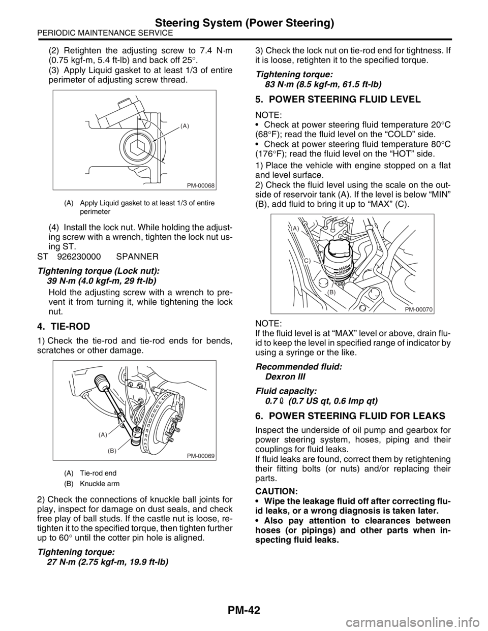
1) Check the tie-rod and tie-rod ends for bends,
scratches or other damage.
2) Check the connections of knuckle ball joints for
play, inspect for damage on dust seals, and check
free play of ball studs. If the castle nut is loose, re-
tighten it to the specified torque, then tighten further
up to 60° until the cotter pin hole is aligned.
Tightening torque:
27 N·m (2.75 kgf-m, 19.9 ft-lb)3) Check the lock nut on tie-rod end for tightness. If
it is loose, retighten it to the specified torque.
Tightening torque:
83 N·m (8.5 kgf-m, 61.5 ft-lb)
5. POWER STEERING FLUID LEVEL
NOTE:
Check at power steering fluid temperature 20°C
(68°F); read the fluid level on the “COLD” side.
Check at power steering fluid temperature 80°C
(176°F); read the fluid level on the “HOT” side.
1) Place the vehicle with engine stopped on a flat
and level surface.
2) Check the fluid level using the scale on the out-
side of reservoir tank (A). If the level is below “MIN”
(B), add fluid to bring it up to “MAX” (C).
NOTE:
If the fluid level is at “MAX” level or above, drain flu-
id to keep the level in specified range of indicator by
using a syringe or the like.
Recommended fluid:
Dexron III
Fluid capacity:
0.72 (0.7 US qt, 0.6 Imp qt)
6. POWER STEERING FLUID FOR LEAKS
Inspect the underside of oil pump and gearbox for
power steering system, hoses, piping and their
couplings for fluid leaks.
If fluid leaks are found, correct them by retightening
their fitting bolts (or nuts) and/or replacing their
parts.
CAUTION:
Wipe the leakage fluid off after correcting flu-
id leaks, or a wrong diagnosis is taken later.
Also pay attention to clearances between
hoses (or pipings) and other parts when in-
specting fluid leaks.
(A) Apply Liquid gasket to at least 1/3 of entire
perimeter
(A) Tie-rod end
(B) Knuckle arm
PM-00068
(A)
PM-00069
(A)
(B)
PM-00070
(A)
(C)
(B)
Page 830 of 2870
FU(H4SO)-48
FUEL INJECTION (FUEL SYSTEM)
Fuel Tank
20.Fuel Tank
A: REMOVAL
WARNING:
Place “NO FIRE” signs near the working area.
Be careful not to spill fuel.
1) Set the vehicle on a lift.
2) Release the fuel pressure.
TION, Fuel.>
3) Drain fuel from the fuel tank.
4) Remove the rear seat.
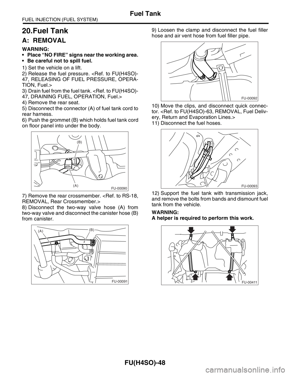
5) Disconnect the connector (A) of fuel tank cord to
rear harness.
6) Push the grommet (B) which holds fuel tank cord
on floor panel into under the body.
7) Remove the rear crossmember.
8) Disconnect the two-way valve hose (A) from
two-way valve and disconnect the canister hose (B)
from canister.9) Loosen the clamp and disconnect the fuel filler
hose and air vent hose from fuel filler pipe.
10) Move the clips, and disconnect quick connec-
tor.
11) Disconnect the fuel hoses.
12) Support the fuel tank with transmission jack,
and remove the bolts from bands and dismount fuel
tank from the vehicle.
WARNING:
A helper is required to perform this work.
(B)
(A)
FU-00090
(A)
(B)
FU-00091
FU-00092
FU-00093
FU-00411
Page 840 of 2870
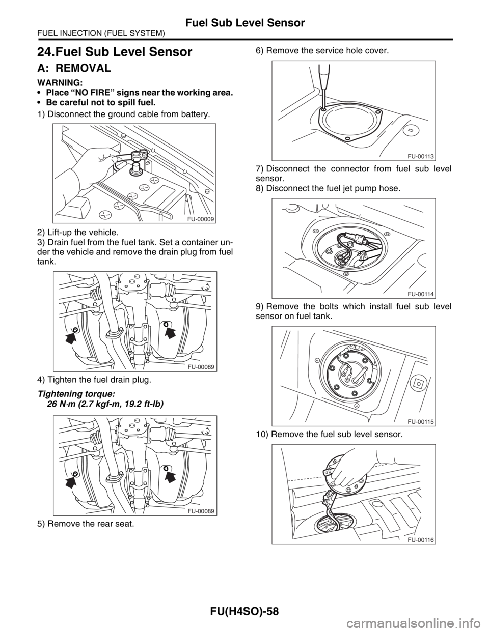
FU(H4SO)-58
FUEL INJECTION (FUEL SYSTEM)
Fuel Sub Level Sensor
24.Fuel Sub Level Sensor
A: REMOVAL
WARNING:
Place “NO FIRE” signs near the working area.
Be careful not to spill fuel.
1) Disconnect the ground cable from battery.
2) Lift-up the vehicle.
3) Drain fuel from the fuel tank. Set a container un-
der the vehicle and remove the drain plug from fuel
tank.
4) Tighten the fuel drain plug.
Tightening torque:
26 N
⋅m (2.7 kgf-m, 19.2 ft-lb)
5) Remove the rear seat.6) Remove the service hole cover.
7) Disconnect the connector from fuel sub level
sensor.
8) Disconnect the fuel jet pump hose.
9) Remove the bolts which install fuel sub level
sensor on fuel tank.
10) Remove the fuel sub level sensor.
FU-00009
FU-00089
FU-00089
FU-00113
FU-00114
FU-00115
FU-00116
Page 940 of 2870
ME(H4SO)-69
MECHANICAL
Cylinder Block
21.Cylinder Block
A: REMOVAL
NOTE:
Before conducting this procedure, drain the engine
oil completely.
1) Remove the intake manifold.
2) Remove the V-belt.
3) Remove the crank pulley.
4) Remove the timing belt cover.
5) Remove the timing belt.
6) Remove the cam sprocket.
7) Remove the crank sprocket.
8) Remove the generator and A/C compressor with
their brackets.
9) Remove the rocker cover.
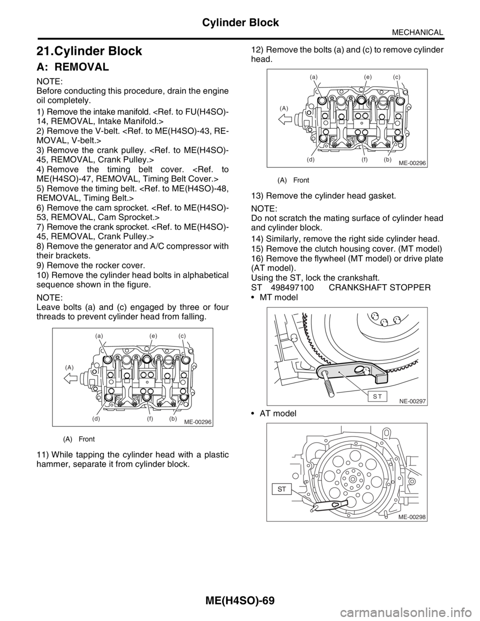
10) Remove the cylinder head bolts in alphabetical
sequence shown in the figure.
NOTE:
Leave bolts (a) and (c) engaged by three or four
threads to prevent cylinder head from falling.
11) While tapping the cylinder head with a plastic
hammer, separate it from cylinder block.12) Remove the bolts (a) and (c) to remove cylinder
head.
13) Remove the cylinder head gasket.
NOTE:
Do not scratch the mating surface of cylinder head
and cylinder block.
14) Similarly, remove the right side cylinder head.
15) Remove the clutch housing cover. (MT model)
16) Remove the flywheel (MT model) or drive plate
(AT model).
Using the ST, lock the crankshaft.
ST 498497100 CRANKSHAFT STOPPER
MT model
AT model
(A) Front
ME-00296
(a)
(b)(c) (e)
(f) (A)
(d)
(A) Front
ME-00296
(a)
(b)(c) (e)
(f) (A)
(d)
NE-00297ST
ME-00298
Page 965 of 2870

ME(H4SO)-94
MECHANICAL
Engine Trouble in General
5. Engine does not return to
idle.Engine control system
Intake system Loosened or cracked vacuum hose A
Others Stuck or damaged throttle valve A
Accelerator cable out of adjustment B
6. Dieseling (Run-on) Engine control system
Cooling system Overheating B
Others Malfunction of evaporative emission control system B
7. After burning in exhaust
systemEngine control system
Intake system Loosened or cracked intake duct C
Loosened or cracked PCV hose C
Loosened or cracked vacuum hose B
Defective PCV valve B
Loosened oil filler cap C
Belt Defective timing B
Compression Incorrect valve clearance B
Loosened spark plugs or defective gasket C
Loosened cylinder head bolts or defective gasket C
Improper valve seating B
Defective valve stem C
Worn or broken valve spring C
Worn or stuck piston rings, cylinder and piston C
Incorrect valve timing A
Lubrication system Incorrect oil pressure C
Cooling system Over cooling C
Others Malfunction of evaporative emission control system C
8. Knocking Engine control system
Intake system Loosened oil filler cap B
Belt Defective timing B
Compression Incorrect valve clearance C
Incorrect valve timing B
Cooling system Overheating A
9. Excessive engine oil con-
sumptionIntake system Loosened or cracked PCV hose A
Defective PCV valve B
Loosened oil filler cap C
Compression Defective valve stem A
Worn or stuck piston rings, cylinder and piston A
Lubrication system Loosened oil pump attaching bolts and defective gas-
ketB
Defective oil filter seal B
Defective crankshaft oil seal B
Defective rocker cover gasket B
Loosened oil drain plug or defective gasket B
Loosened oil pan fitting bolts or defective oil pan B TROUBLE PROBLEM PARTS, ETC. POSSIBLE CAUSE RANK
Page 1018 of 2870
CO(H4SO)-35
COOLING
Radiator Main Fan and Fan Motor
8. Radiator Main Fan and Fan
Motor
A: REMOVAL
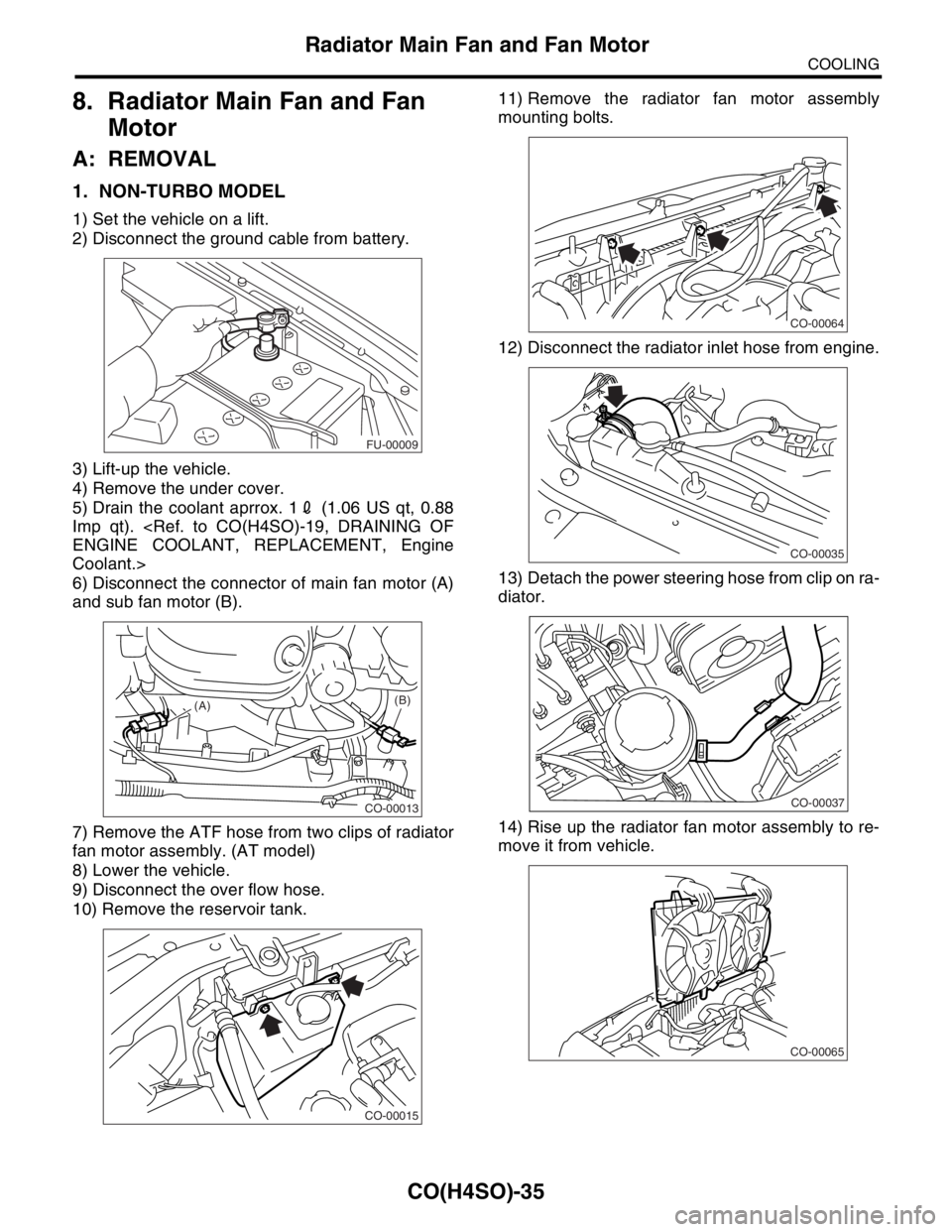
1. NON-TURBO MODEL
1) Set the vehicle on a lift.
2) Disconnect the ground cable from battery.
3) Lift-up the vehicle.
4) Remove the under cover.
5) Drain the coolant aprrox. 12 (1.06 US qt, 0.88
Imp qt).
Coolant.>
6) Disconnect the connector of main fan motor (A)
and sub fan motor (B).
7) Remove the ATF hose from two clips of radiator
fan motor assembly. (AT model)
8) Lower the vehicle.
9) Disconnect the over flow hose.
10) Remove the reservoir tank.11) Remove the radiator fan motor assembly
mounting bolts.
12) Disconnect the radiator inlet hose from engine.
13) Detach the power steering hose from clip on ra-
diator.
14) Rise up the radiator fan motor assembly to re-
move it from vehicle.
FU-00009
CO-00013
(A)(B)
CO-00015
CO-00064
CO-00035
CO-00037
CO-00065
Page 1019 of 2870
CO(H4SO)-36
COOLING
Radiator Main Fan and Fan Motor
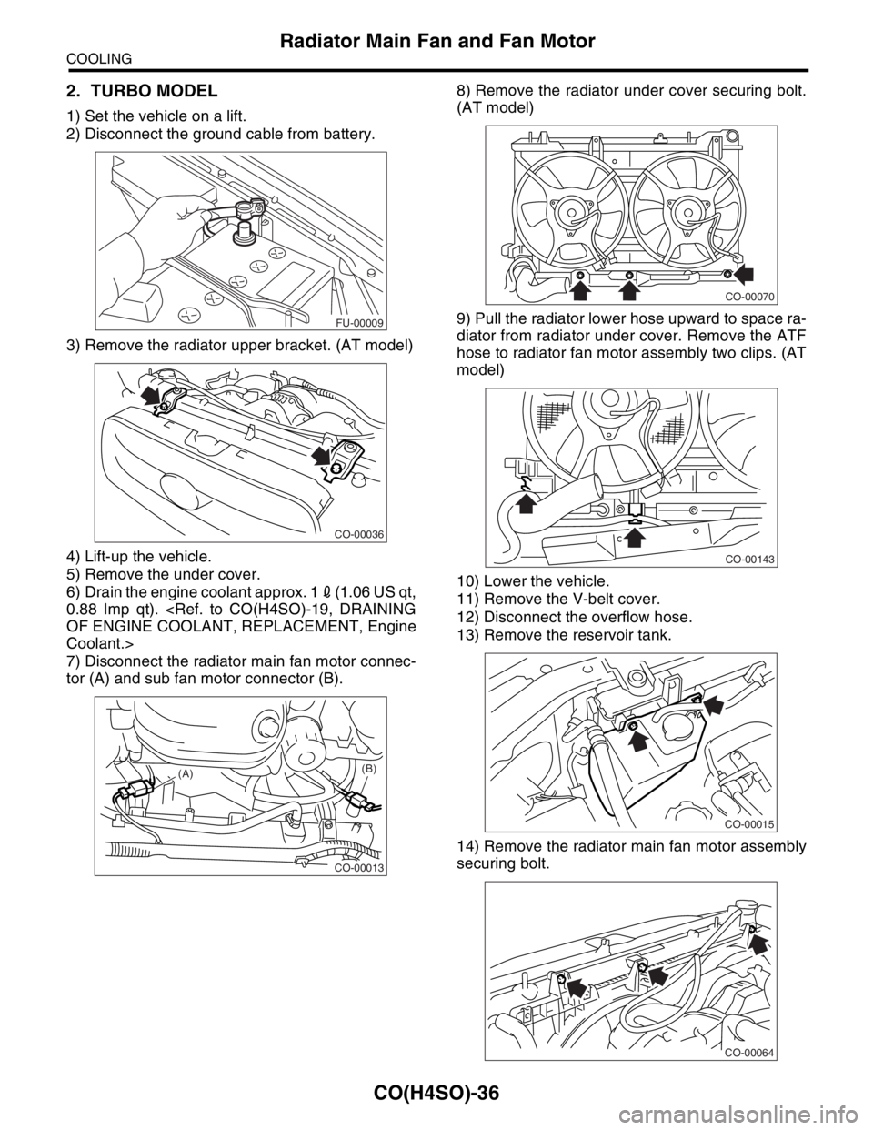
2. TURBO MODEL
1) Set the vehicle on a lift.
2) Disconnect the ground cable from battery.
3) Remove the radiator upper bracket. (AT model)
4) Lift-up the vehicle.
5) Remove the under cover.
6) Drain the engine coolant approx. 12(1.06 US qt,
0.88 Imp qt).
Coolant.>
7) Disconnect the radiator main fan motor connec-
tor (A) and sub fan motor connector (B).8) Remove the radiator under cover securing bolt.
(AT model)
9) Pull the radiator lower hose upward to space ra-
diator from radiator under cover. Remove the ATF
hose to radiator fan motor assembly two clips. (AT
model)
10) Lower the vehicle.
11) Remove the V-belt cover.
12) Disconnect the overflow hose.
13) Remove the reservoir tank.
14) Remove the radiator main fan motor assembly
securing bolt.
FU-00009
CO-00036
CO-00013
(A)(B)
CO-00070
CO-00143
CO-00015
CO-00064