airbag off SUBARU FORESTER 2004 Service Repair Manual
[x] Cancel search | Manufacturer: SUBARU, Model Year: 2004, Model line: FORESTER, Model: SUBARU FORESTER 2004Pages: 2870, PDF Size: 38.67 MB
Page 59 of 2870
AC-3
HVAC SYSTEM (AUTO A/C)(DIAGNOSTIC)
General Description
2. General Description
A: CAUTION
1) Never connect the battery in reverse polarity.
Auto A/C control module may be destroyed instant-
ly.
2) Do not disconnect the battery terminals while the
engine is running.
A large counter electromotive force will be generat-
ed in the generator, and this voltage may damage
electronic parts such as auto A/C control module,
etc.
3) Before disconnecting the connectors of each
sensor and the auto A/C control module, be sure to
turn off the ignition switch.
Auto A/C control module may be damaged.
4) Every A/C-related part is a precision part. Do not
drop them.
5) Airbag system wiring harness is routed near the
A/C control panel (auto A/C control module) and
junction box.
CAUTION:
For airbag system, yellow-colored wiring har-
ness and connectors are all used. Do not use
the electrical test equipment on these circuits.
Be careful not to damage the airbag system
wiring harness when servicing the A/C control
panel (auto A/C control module) and junction
box.
B: INSPECTION
Before performing the diagnosis, check the follow-
ing items which might affect A/C system problems.
1. BATTERY
1) Measure battery voltage and specific gravity of
electrolyte.
Standard voltage: 12 V
Specific gravity: More than 1.260
2) Check the condition of the fuses for A/C system
power supply and other fuses.
3) Check the condition of harness and harness
connector connections.
2. ASPIRATOR HOSE
1) Turn the ignition switch to ON, and press the A/
C switch.
2) Turn the temperature control dial at maximum
hot position.
3) Press the defroster switch.
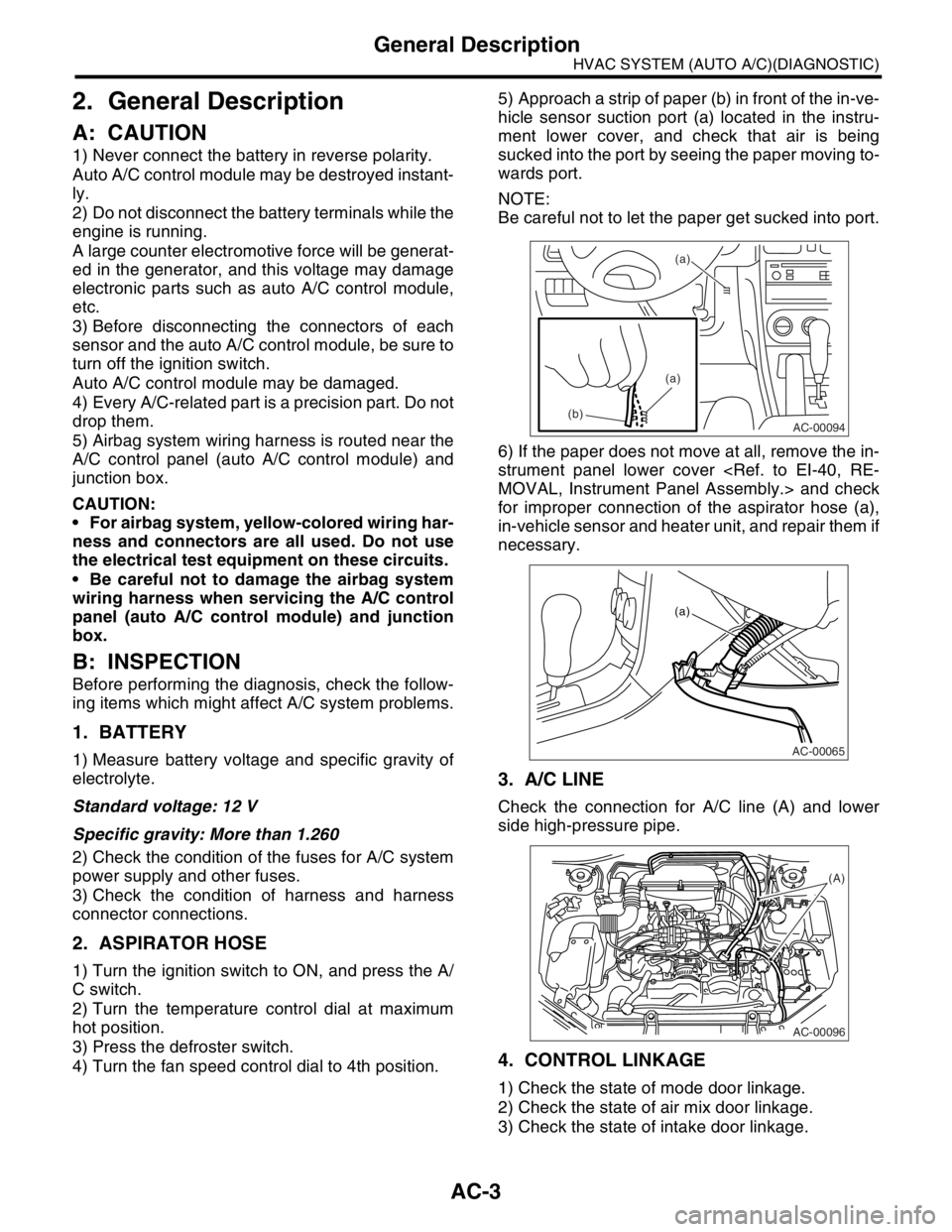
4) Turn the fan speed control dial to 4th position.5) Approach a strip of paper (b) in front of the in-ve-
hicle sensor suction port (a) located in the instru-
ment lower cover, and check that air is being
sucked into the port by seeing the paper moving to-
wards port.
NOTE:
Be careful not to let the paper get sucked into port.
6) If the paper does not move at all, remove the in-
strument panel lower cover
for improper connection of the aspirator hose (a),
in-vehicle sensor and heater unit, and repair them if
necessary.
3. A/C LINE
Check the connection for A/C line (A) and lower
side high-pressure pipe.
4. CONTROL LINKAGE
1) Check the state of mode door linkage.
2) Check the state of air mix door linkage.
3) Check the state of intake door linkage.
AC-00094
(a)
(a)
(b)
AC-00065
(a)
AC-00096
(A)
Page 103 of 2870
AB-3
AIRBAG SYSTEM
General Description
B: CAUTION
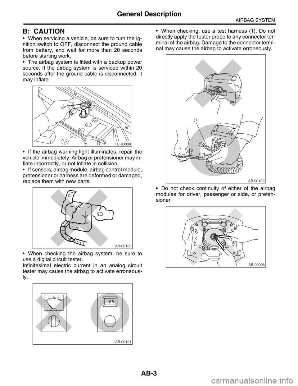
When servicing a vehicle, be sure to turn the ig-
nition switch to OFF, disconnect the ground cable
from battery, and wait for more than 20 seconds
before starting work.
The airbag system is fitted with a backup power
source. If the airbag system is serviced within 20
seconds after the ground cable is disconnected, it
may inflate.
If the airbag warning light illuminates, repair the
vehicle immediately. Airbag or pretensioner may in-
flate incorrectly, or not inflate in collision.
If sensors, airbag module, airbag control module,
pretensioner or harness are deformed or damaged,
replace them with new parts.
When checking the airbag system, be sure to
use a digital circuit tester.
Infinitesimal electric current in an analog circuit
tester may cause the airbag to activate erroneous-
ly. When checking, use a test harness (1). Do not
directly apply the tester probe to any connector ter-
minal of the airbag. Damage to the connector termi-
nal may cause the airbag to activate erroneously.
Do not check continuity of either of the airbag
modules for driver, passenger or side, or preten-
sioner.
FU-00009
AB-00120
AB-00121
AB-00122
(1)
AB-00006
Page 114 of 2870
AB-14
AIRBAG SYSTEM
Driver’s Airbag Module
4. Driver’s Airbag Module
A: REMOVAL
CAUTION:
Refer to “CAUTION” in General Description be-
fore handing the airbag module.
1) Position the front wheels straight ahead. (After
moving the vehicle more than 5 m (16 ft) with front
wheels positioned straight ahead, make sure that
the vehicle moves straight ahead).
2) Turn the ignition switch to OFF.
3) Disconnect the ground cable from battery, and
wait for at least 20 seconds before starting work.
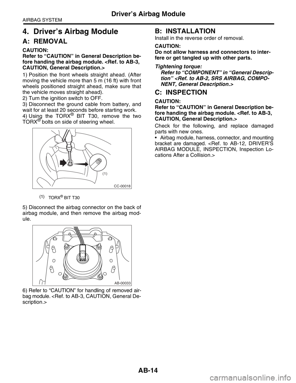
4) Using the TORX
® BIT T30, remove the two
TORX® bolts on side of steering wheel.
5) Disconnect the airbag connector on the back of
airbag module, and then remove the airbag mod-
ule.
6) Refer to “CAUTION” for handling of removed air-
bag module.
B: INSTALLATION
Install in the reverse order of removal.
CAUTION:
Do not allow harness and connectors to inter-
fere or get tangled up with other parts.
Tightening torque:
Refer to “COMPONENT” in “General Descrip-
tion”
C: INSPECTION
CAUTION:
Refer to “CAUTION” in General Description be-
fore handing the airbag module.
Check for the following, and replace damaged
parts with new ones.
Airbag module, harness, connector, and mounting
bracket are damaged.
cations After a Collision.>
(1)
TORX® BIT T30
CC-00018
(1)
AB-00033
Page 115 of 2870
AB-15
AIRBAG SYSTEM
Passenger’s Airbag Module
5. Passenger’s Airbag Module
A: REMOVAL
CAUTION:
Refer to “CAUTION” in General Description be-
fore handing the airbag module.
1) Turn the ignition switch to OFF.
2) Disconnect the ground cable from battery, and
wait for at least 20 seconds before starting work.
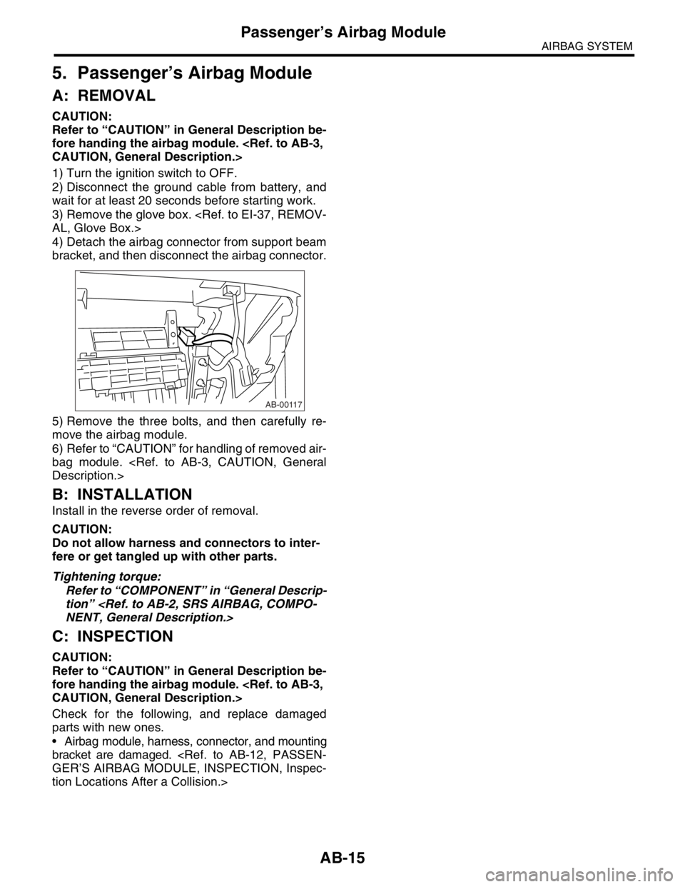
3) Remove the glove box.
4) Detach the airbag connector from support beam
bracket, and then disconnect the airbag connector.
5) Remove the three bolts, and then carefully re-
move the airbag module.
6) Refer to “CAUTION” for handling of removed air-
bag module.
B: INSTALLATION
Install in the reverse order of removal.
CAUTION:
Do not allow harness and connectors to inter-
fere or get tangled up with other parts.
Tightening torque:
Refer to “COMPONENT” in “General Descrip-
tion”
C: INSPECTION
CAUTION:
Refer to “CAUTION” in General Description be-
fore handing the airbag module.
Check for the following, and replace damaged
parts with new ones.
Airbag module, harness, connector, and mounting
bracket are damaged.
tion Locations After a Collision.>
AB-00117
Page 116 of 2870
AB-16
AIRBAG SYSTEM
Side Airbag Module
6. Side Airbag Module
A: REMOVAL
CAUTION:
Before working on the airbag module, refer to
the “CAUTION” in General Description.
NOTE:
Remove the passenger’s side by referring to driv-
er’s side.
1) Turn the ignition switch to OFF.
2) Disconnect the ground cable from battery, and
wait for at least 20 seconds before starting work.
3) Remove the front seat from the vehicle.
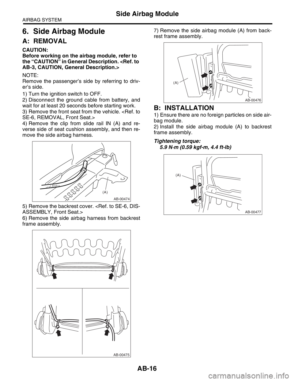
4) Remove the clip from slide rail IN (A) and re-
verse side of seat cushion assembly, and then re-
move the side airbag harness.
5) Remove the backrest cover.
6) Remove the side airbag harness from backrest
frame assembly.7) Remove the side airbag module (A) from back-
rest frame assembly.
B: INSTALLATION
1) Ensure there are no foreign particles on side air-
bag module.
2) Install the side airbag module (A) to backrest
frame assembly.
Tightening torque:
5.9 N·m (0.59 kgf-m, 4.4 ft-lb)
AB-00474
(A)
AB-00475
AB-00476
(A)
AB-00477
(A)
Page 118 of 2870
AB-18
AIRBAG SYSTEM
Airbag Control Module
7. Airbag Control Module
A: REMOVAL
CAUTION:
Do not disassemble the airbag control mod-
ule.
If the airbag control module is deformed or if
water damage is suspected, replace the airbag
control module with a new part.
Do not drop the airbag control module.
After removal, keep the airbag control mod-
ule on a dry, clean surface away from moisture,
heat, and dust.
1) Turn the ignition switch to OFF.
2) Disconnect the ground cable from battery, and
wait for at least 20 seconds before starting work.
3) Remove the console cover.
4) Remove the center console panel.
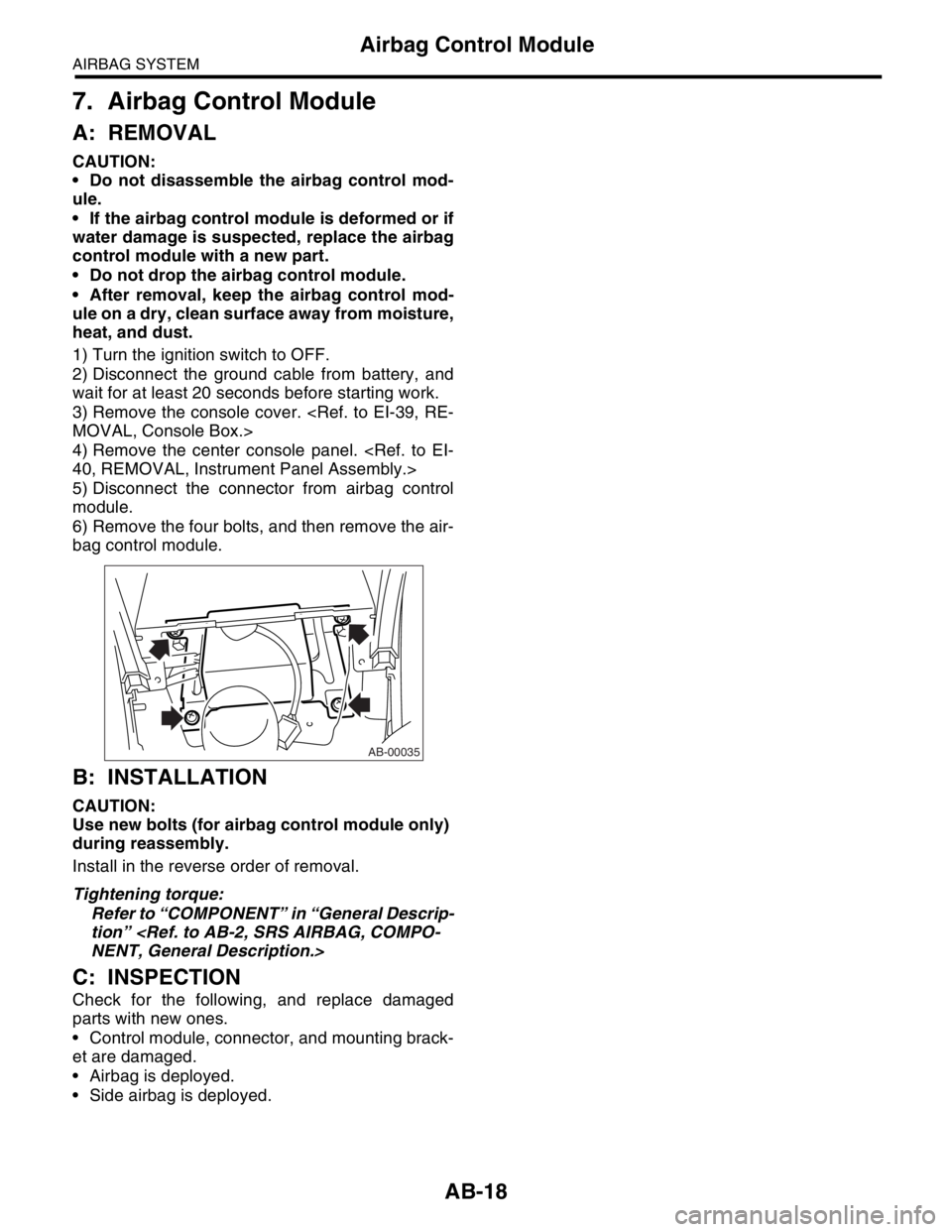
5) Disconnect the connector from airbag control
module.
6) Remove the four bolts, and then remove the air-
bag control module.
B: INSTALLATION
CAUTION:
Use new bolts (for airbag control module only)
during reassembly.
Install in the reverse order of removal.
Tightening torque:
Refer to “COMPONENT” in “General Descrip-
tion”
C: INSPECTION
Check for the following, and replace damaged
parts with new ones.
Control module, connector, and mounting brack-
et are damaged.
Airbag is deployed.
Side airbag is deployed.
AB-00035
Page 119 of 2870
AB-19
AIRBAG SYSTEM
Side Airbag Sensor
8. Side Airbag Sensor
A: REMOVAL
1) Turn the ignition switch to OFF.
2) Disconnect the ground cable from battery, and
wait for at least 20 seconds before starting work.
3) Remove the outer belt (FRONT).
Belt.>
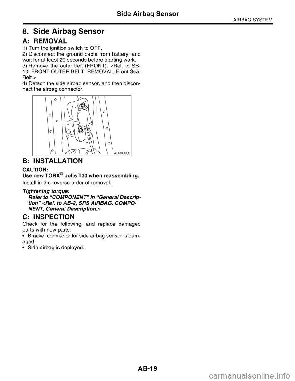
4) Detach the side airbag sensor, and then discon-
nect the airbag connector.
B: INSTALLATION
CAUTION:
Use new TORX® bolts T30 when reassembling.
Install in the reverse order of removal.
Tightening torque:
Refer to “COMPONENT” in “General Descrip-
tion”
C: INSPECTION
Check for the following, and replace damaged
parts with new parts.
Bracket connector for side airbag sensor is dam-
aged.
Side airbag is deployed.
AB-00036
Page 120 of 2870
AB-20
AIRBAG SYSTEM
Roll Connector
9. Roll Connector
A: REMOVAL
1) Turn the ignition switch to OFF.
2) Disconnect the ground cable from battery, and
wait for at least 20 seconds before starting work.
3) Remove the driver’s airbag module.
4) Remove the steering wheel.
5) Remove the steering column cover.
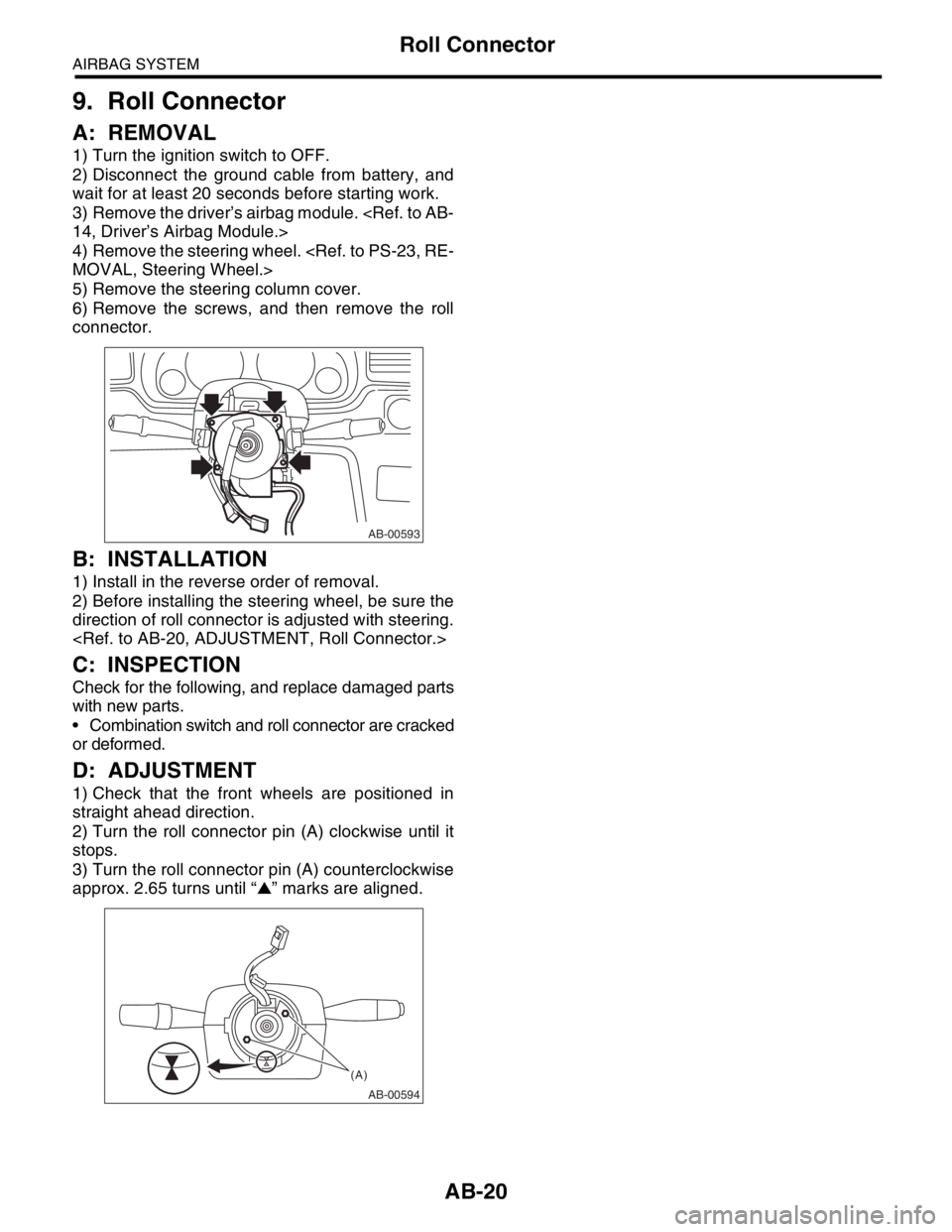
6) Remove the screws, and then remove the roll
connector.
B: INSTALLATION
1) Install in the reverse order of removal.
2) Before installing the steering wheel, be sure the
direction of roll connector is adjusted with steering.
C: INSPECTION
Check for the following, and replace damaged parts
with new parts.
Combination switch and roll connector are cracked
or deformed.
D: ADJUSTMENT
1) Check that the front wheels are positioned in
straight ahead direction.
2) Turn the roll connector pin (A) clockwise until it
stops.
3) Turn the roll connector pin (A) counterclockwise
approx. 2.65 turns until “▲” marks are aligned.
AB-00593
AB-00594
(A)
Page 121 of 2870
AB-21
AIRBAG SYSTEM
Front Sub Sensor
10.Front Sub Sensor
A: REMOVAL
1) Turn the ignition switch to OFF.
2) Disconnect the ground cable from battery, and
wait for at least 20 seconds before starting work.
3) Remove the front grille and front grille side.
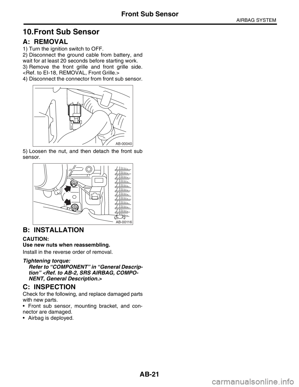
4) Disconnect the connector from front sub sensor.
5) Loosen the nut, and then detach the front sub
sensor.
B: INSTALLATION
CAUTION:
Use new nuts when reassembling.
Install in the reverse order of removal.
Tightening torque:
Refer to “COMPONENT” in “General Descrip-
tion”
C: INSPECTION
Check for the following, and replace damaged parts
with new parts.
Front sub sensor, mounting bracket, and con-
nector are damaged.
Airbag is deployed.
AB-00040
AB-00116
Page 122 of 2870
AB-22
AIRBAG SYSTEM
Airbag Module Disposal (Deployment Processing On Vehicle)
11.Airbag Module Disposal (De-
ployment Processing On Ve-
hicle)
A: OPERATION
CAUTION:
Do not discard an undeployed airbag mod-
ules because it may cause a serious personal
injury when accidentally deployed.
As a rule, the airbag module should be de-
ployed while still installed in the vehicle. Do not
remove the airbag modules unless necessary.
Deployment of the airbag module should be
done on a flat place free from any possible dan-
ger. Avoid deploying outdoors during rainy or
windy weather.
Deploying the airbag module causes a high
explosive noise, be sure to warn people in the
area, and do not allow anyone within a 5 m (16
ft) radius of the disposal site.
Some smoke will be emitted from deployment
of the airbag module. Therefore, it must be de-
ployed in a well-ventilated place with no smoke
detector nearby.
Wear protective gloves, safety goggles and
earplugs during this operation. Wash your hands
afterwards.
After deployment, the airbag module will be
especially hot, leave it unattended for 40 min-
utes, and then discard it.
Do not let water get on the deployed airbag
module.
Wrap the deployed airbag module in an air-
tight vinyl bag, and discard it.
If circumstances do not permit the airbag
module deployment, contact the SUBARU deal-
er.
1. DRIVER’S AIRBAG MODULE
1) Turn the ignition switch to OFF.
2) Disconnect the ground cable from battery and
wait for at least 20 seconds before starting work.
3) Remove the lower cover.
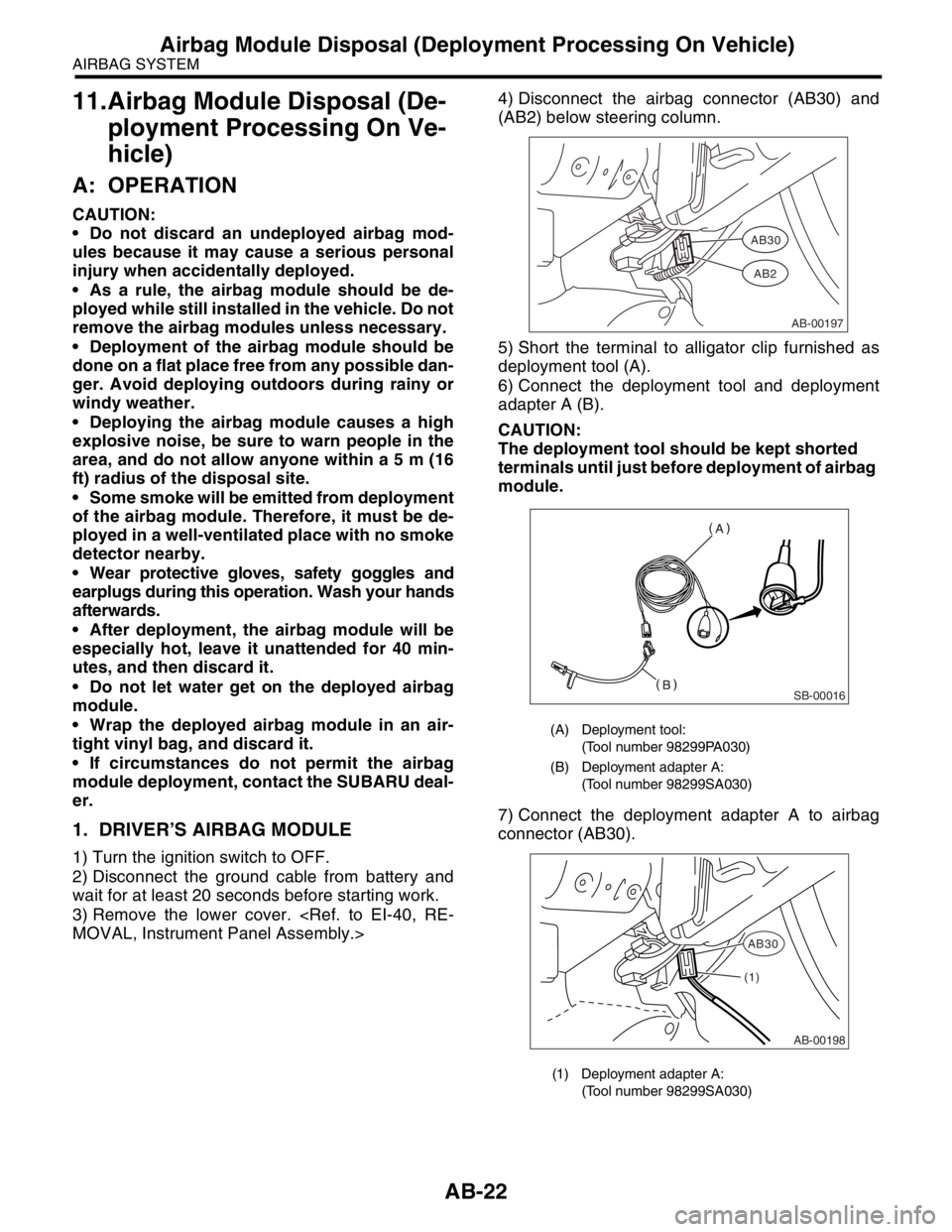
(AB2) below steering column.
5) Short the terminal to alligator clip furnished as
deployment tool (A).
6) Connect the deployment tool and deployment
adapter A (B).
CAUTION:
The deployment tool should be kept shorted
terminals until just before deployment of airbag
module.
7) Connect the deployment adapter A to airbag
connector (AB30).
(A) Deployment tool:
(Tool number 98299PA030)
(B) Deployment adapter A:
(Tool number 98299SA030)
(1) Deployment adapter A:
(Tool number 98299SA030)
AB-00197
AB30
AB2
SB-00016
AB-00198
AB30
(1)