crankshaft SUBARU FORESTER 2004 Service Repair Manual
[x] Cancel search | Manufacturer: SUBARU, Model Year: 2004, Model line: FORESTER, Model: SUBARU FORESTER 2004Pages: 2870, PDF Size: 38.67 MB
Page 750 of 2870
PM-13
PERIODIC MAINTENANCE SERVICE
Timing Belt
7. Timing Belt
A: REPLACEMENT
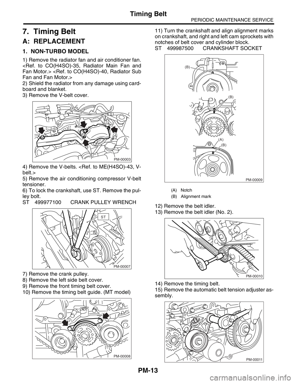
1. NON-TURBO MODEL
1) Remove the radiator fan and air conditioner fan.
2) Shield the radiator from any damage using card-
board and blanket.
3) Remove the V-belt cover.
4) Remove the V-belts.
5) Remove the air conditioning compressor V-belt
tensioner.
6) To lock the crankshaft, use ST. Remove the pul-
ley bolt.
ST 499977100 CRANK PULLEY WRENCH
7) Remove the crank pulley.
8) Remove the left side belt cover.
9) Remove the front timing belt cover.
10) Remove the timing belt guide. (MT model)11) Turn the crankshaft and align alignment marks
on crankshaft, and right and left cam sprockets with
notches of belt cover and cylinder block.
ST 499987500 CRANKSHAFT SOCKET
12) Remove the belt idler.
13) Remove the belt idler (No. 2).
14) Remove the timing belt.
15) Remove the automatic belt tension adjuster as-
sembly.
PM-00003
PM-00007
ST
PM-00008
(A) Notch
(B) Alignment mark
PM-00009
(B)
(B)
(B) (A)
PM-00010
PM-00011
Page 751 of 2870
PM-14
PERIODIC MAINTENANCE SERVICE
Timing Belt
16) Install in the reverse order of removal.
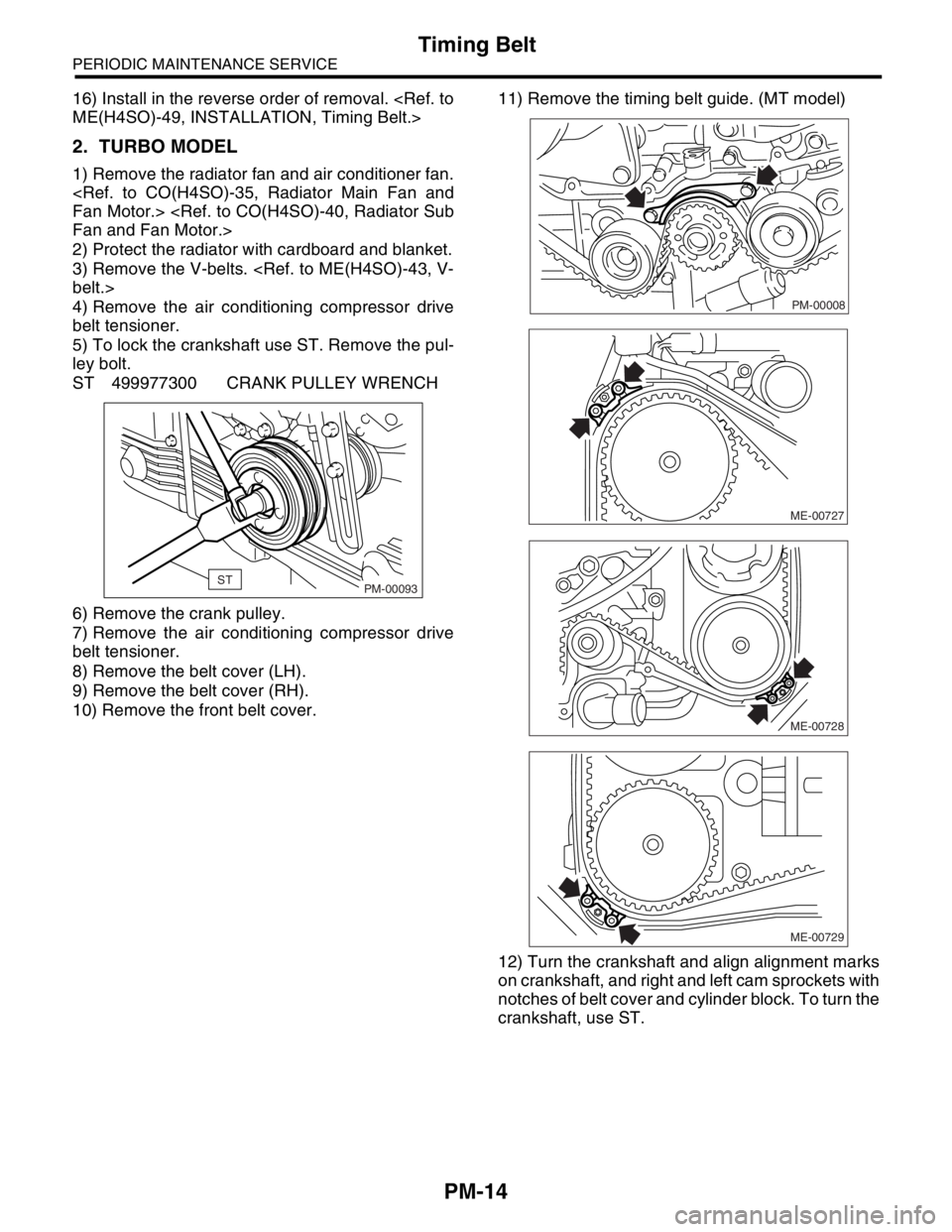
2. TURBO MODEL
1) Remove the radiator fan and air conditioner fan.
2) Protect the radiator with cardboard and blanket.
3) Remove the V-belts.
4) Remove the air conditioning compressor drive
belt tensioner.
5) To lock the crankshaft use ST. Remove the pul-
ley bolt.
ST 499977300 CRANK PULLEY WRENCH
6) Remove the crank pulley.
7) Remove the air conditioning compressor drive
belt tensioner.
8) Remove the belt cover (LH).
9) Remove the belt cover (RH).
10) Remove the front belt cover.11) Remove the timing belt guide. (MT model)
12) Turn the crankshaft and align alignment marks
on crankshaft, and right and left cam sprockets with
notches of belt cover and cylinder block. To turn the
crankshaft, use ST.
STPM-00093
PM-00008
ME-00727
ME-00728
ME-00729
Page 752 of 2870
PM-15
PERIODIC MAINTENANCE SERVICE
Timing Belt
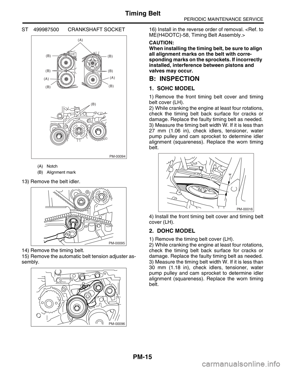
ST 499987500 CRANKSHAFT SOCKET
13) Remove the belt idler.
14) Remove the timing belt.
15) Remove the automatic belt tension adjuster as-
sembly.16) Install in the reverse order of removal.
CAUTION:
When installing the timing belt, be sure to align
all alignment marks on the belt with corre-
sponding marks on the sprockets. If incorrectly
installed, interference between pistons and
valves may occur.
B: INSPECTION
1. SOHC MODEL
1) Remove the front timing belt cover and timing
belt cover (LH).
2) While cranking the engine at least four rotations,
check the timing belt back surface for cracks or
damage. Replace the faulty timing belt as needed.
3) Measure the timing belt width W. If it is less than
27 mm (1.06 in), check idlers, tensioner, water
pump pulley and cam sprocket to determine idler
alignment (squareness). Replace the worn timing
belt.
4) Install the front timing belt cover and timing belt
cover (LH).
2. DOHC MODEL
1) Remove the timing belt cover (LH).
2) While cranking the engine at least four rotations,
check the timing belt back surface for cracks or
damage. Replace the faulty timing belt as needed.
3) Measure the timing belt width W. If it is less than
30 mm (1.18 in), check idlers, tensioner, water
pump pulley and cam sprocket to determine idler
alignment (squareness). Replace the worn timing
belt.
(A) Notch
(B) Alignment mark
PM-00094
(A)
(B)
(B)
(B) (A)(B)
(B)
(B)(A)
(B)
PM-00095
PM-00096
w
PM-00016
Page 783 of 2870

FUEL INJECTION (FUEL SYSTEM)
FU(H4SO)
Page
1. General Description ....................................................................................2
2. Throttle Body .............................................................................................13
3. Intake Manifold ..........................................................................................14
4. Engine Coolant Temperature Sensor........................................................25
5. Crankshaft Position Sensor.......................................................................26
6. Camshaft Position Sensor.........................................................................27
7. Knock Sensor ............................................................................................28
8. Throttle Position Sensor ............................................................................29
9. Manifold Absolute Pressure Sensor ..........................................................31
10. Intake Air Temperature Sensor .................................................................32
11. Idle Air Control Solenoid Valve .................................................................33
12. EGR Valve ................................................................................................34
13. Fuel Injector ..............................................................................................35
14. Front Oxygen (A/F) Sensor .......................................................................40
15. Rear Oxygen Sensor.................................................................................42
16. Engine Control Module (ECM) ..................................................................44
17. Main Relay ................................................................................................45
18. Fuel Pump Relay.......................................................................................46
19. Fuel ...........................................................................................................47
20. Fuel Tank ..................................................................................................48
21. Fuel Filler Pipe ..........................................................................................51
22. Fuel Pump .................................................................................................55
23. Fuel Level Sensor .....................................................................................57
24. Fuel Sub Level Sensor ..............................................................................58
25. Fuel Filter ..................................................................................................60
26. Fuel Cut Valve...........................................................................................61
27. Fuel Damper Valve ...................................................................................62
28. Fuel Delivery, Return and Evaporation Lines............................................63
29. Fuel System Trouble in General ...............................................................66
Page 788 of 2870
FU(H4SO)-6
FUEL INJECTION (FUEL SYSTEM)
General Description
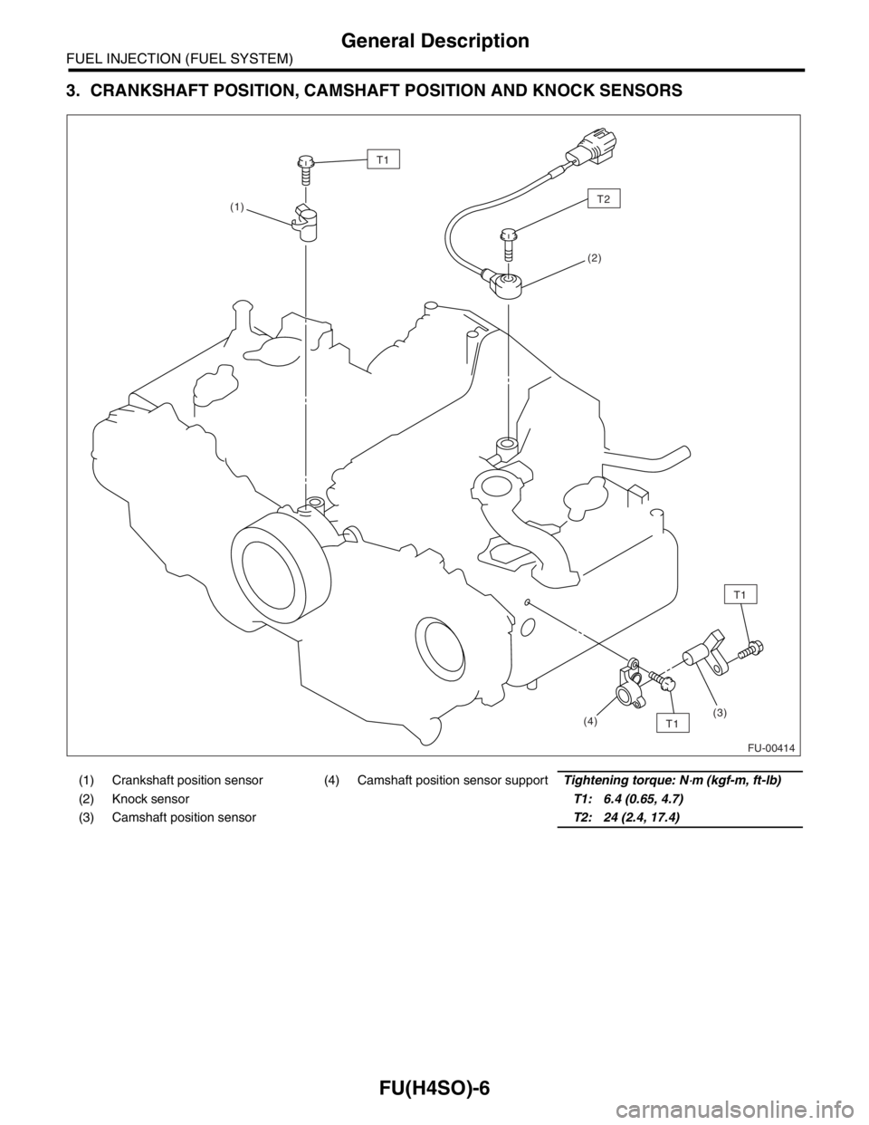
3. CRANKSHAFT POSITION, CAMSHAFT POSITION AND KNOCK SENSORS
(1) Crankshaft position sensor (4) Camshaft position sensor supportTightening torque: N⋅m (kgf-m, ft-lb)
(2) Knock sensorT1: 6.4 (0.65, 4.7)
(3) Camshaft position sensorT2: 24 (2.4, 17.4)
FU-00414
T1
(1)
(2)
T1
T1(3)
(4)
T2
Page 797 of 2870
FU(H4SO)-15
FUEL INJECTION (FUEL SYSTEM)
Intake Manifold
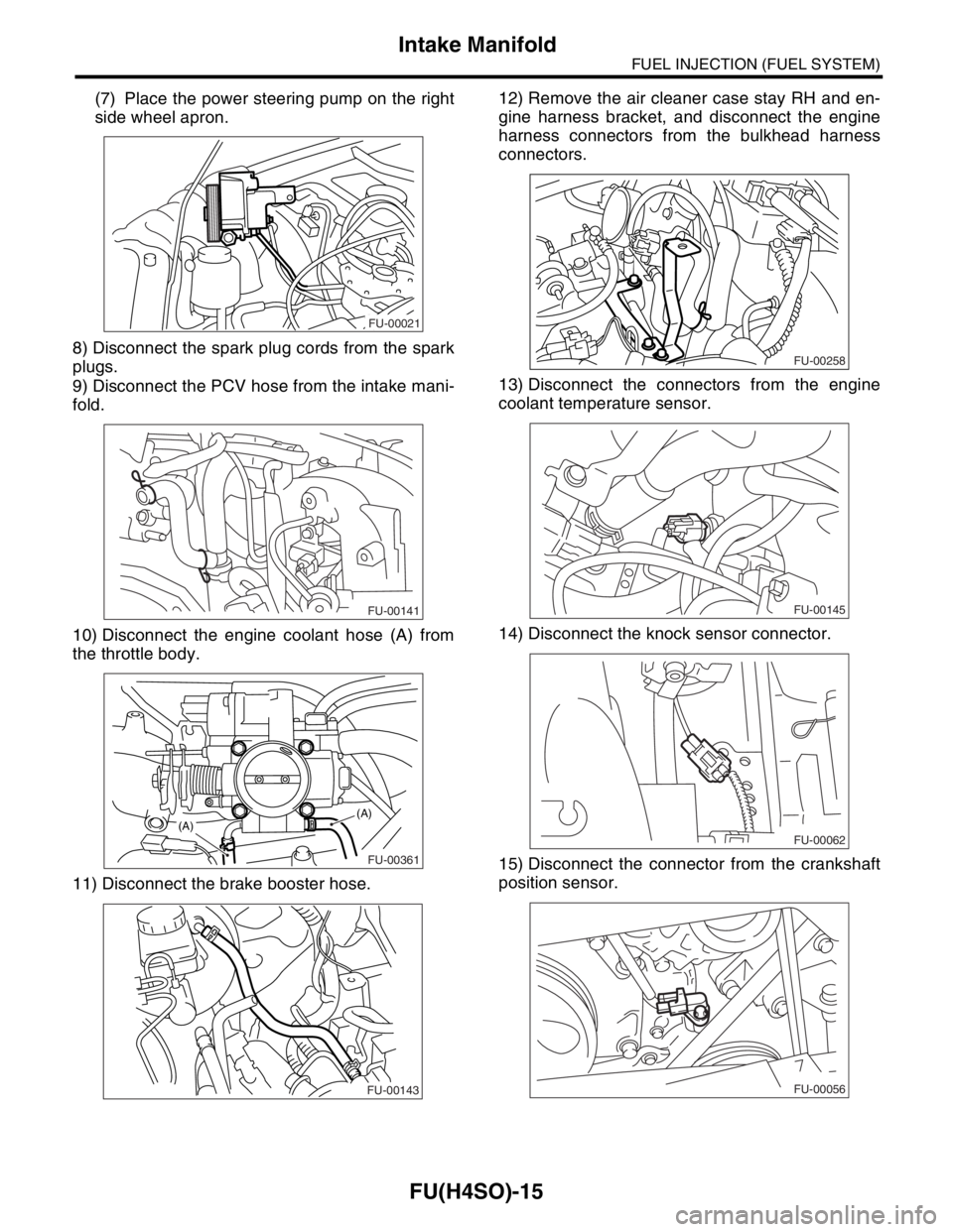
(7) Place the power steering pump on the right
side wheel apron.
8) Disconnect the spark plug cords from the spark
plugs.
9) Disconnect the PCV hose from the intake mani-
fold.
10) Disconnect the engine coolant hose (A) from
the throttle body.
11) Disconnect the brake booster hose.12) Remove the air cleaner case stay RH and en-
gine harness bracket, and disconnect the engine
harness connectors from the bulkhead harness
connectors.
13) Disconnect the connectors from the engine
coolant temperature sensor.
14) Disconnect the knock sensor connector.
15) Disconnect the connector from the crankshaft
position sensor.
FU-00021
FU-00141
FU-00361
(A)(A)
FU-00143
FU-00258
FU-00145
FU-00062
FU-00056
Page 799 of 2870
FU(H4SO)-17
FUEL INJECTION (FUEL SYSTEM)
Intake Manifold
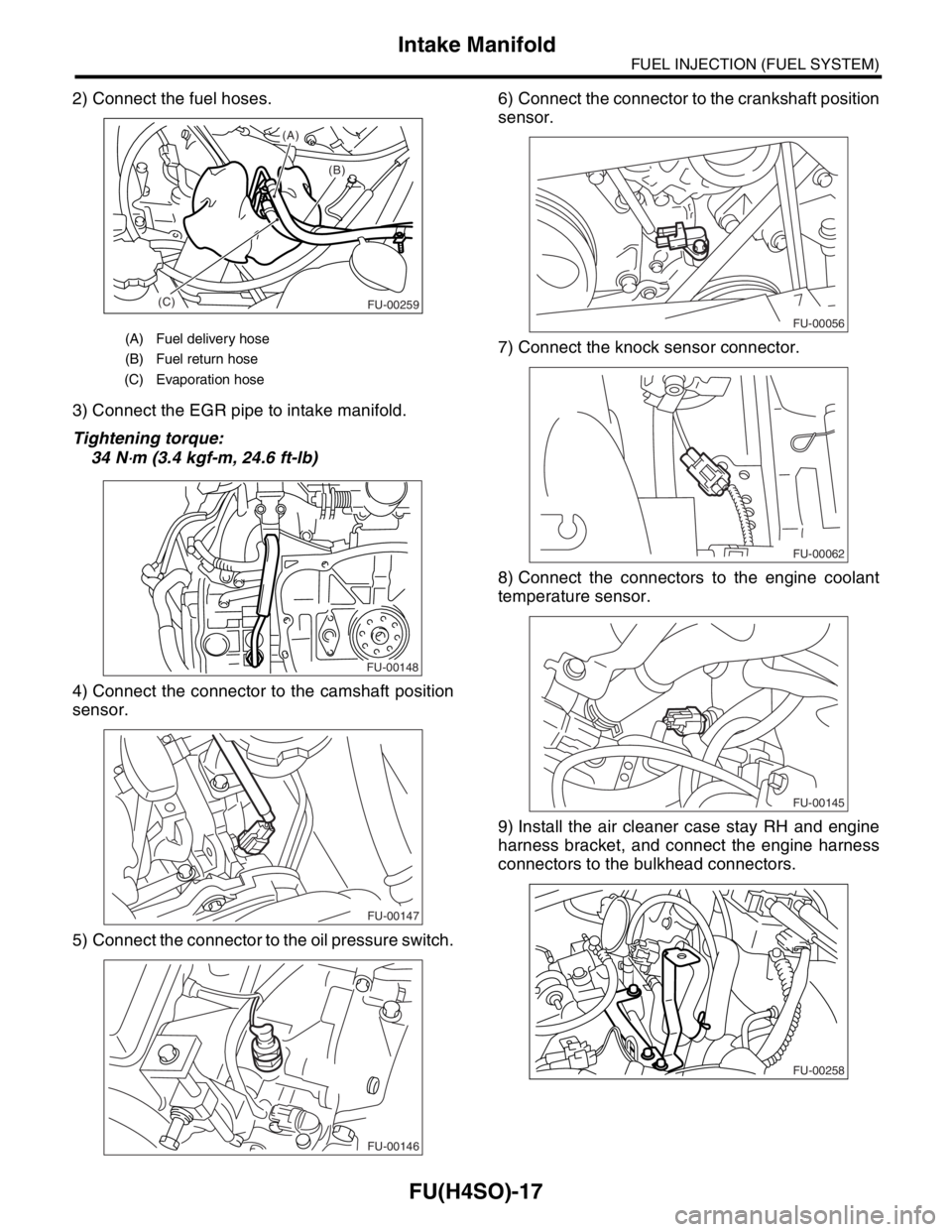
2) Connect the fuel hoses.
3) Connect the EGR pipe to intake manifold.
Tightening torque:
34 N
⋅m (3.4 kgf-m, 24.6 ft-lb)
4) Connect the connector to the camshaft position
sensor.
5) Connect the connector to the oil pressure switch.6) Connect the connector to the crankshaft position
sensor.
7) Connect the knock sensor connector.
8) Connect the connectors to the engine coolant
temperature sensor.
9) Install the air cleaner case stay RH and engine
harness bracket, and connect the engine harness
connectors to the bulkhead connectors.
(A) Fuel delivery hose
(B) Fuel return hose
(C) Evaporation hose
(B) (A)
(C)
FU-00259
FU-00148
FU-00147
FU-00146
FU-00056
FU-00062
FU-00145
FU-00258
Page 808 of 2870
FU(H4SO)-26
FUEL INJECTION (FUEL SYSTEM)
Crankshaft Position Sensor
5. Crankshaft Position Sensor
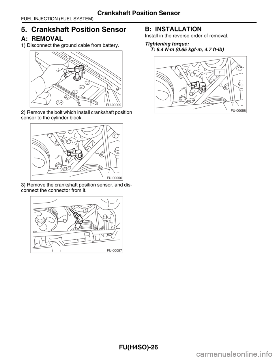
A: REMOVAL
1) Disconnect the ground cable from battery.
2) Remove the bolt which install crankshaft position
sensor to the cylinder block.
3) Remove the crankshaft position sensor, and dis-
connect the connector from it.
B: INSTALLATION
Install in the reverse order of removal.
Tightening torque:
T: 6.4 N
⋅m (0.65 kgf-m, 4.7 ft-lb)
FU-00009
FU-00056
FU-00057
FU-00058
T
Page 874 of 2870

ME(H4SO)-5
MECHANICAL
General Description
CrankshaftBend limit mm (in) 0.035 (0.0014)
Crank pin and
crank journalmm (in)Out-of-roundness 0.020 (0.0008) or less
Grinding limit 0.250 (0.0098)
Crank pin outer diameter mm (in)STD 51.984 — 52.000 (2.0466 — 2.0472)
0.03 (0.0012) US 51.954 — 51.970 (2.0454 — 2.0461)
0.05 (0.0020) US 51.934 — 51.950 (2.0446 — 2.0453)
0.25 (0.0098) US 51.734 — 51.750 (2.0368 — 2.0374)
Crank journal
outer diametermm (in)#1, #3STD 59.992 — 60.008 (2.3619 — 2.3625)
0.03 (0.0012) US 59.962 — 59.978 (2.3607 — 2.3613)
0.05 (0.0020) US 59.942 — 59.958 (2.3599 — 2.3605)
0.25 (0.0098) US 59.742 — 59.758 (2.3520 — 2.3527)
#2, #4, #5STD 59.992 — 60.008 (2.3619 — 2.3625)
0.03 (0.0012) US 59.962 — 59.978 (2.3607 — 2.3613)
0.05 (0.0020) US 59.942 — 59.958 (2.3599 — 2.3605)
0.25 (0.0098) US 59.742 — 59.758 (2.3520 — 2.3527)
Side clearance mm (in)STD 0.030 — 0.115 (0.0012 — 0.0045)
Limit 0.25 (0.0098)
Oil clearance mm (in)#1STD 0.010 — 0.030 (0.0004 — 0.0012)
Limit 0.040 (0.0016)
#2STD 0.010 — 0.030 (0.0004 — 0.0012)
Limit 0.045 (0.0018)
#3STD 0.010 — 0.030 (0.0004 — 0.0012)
Limit 0.040 (0.0016)
#4STD 0.010 — 0.030 (0.0004 — 0.0012)
Limit 0.045 (0.0018)
#5STD 0.010 — 0.030 (0.0004 — 0.0012)
Limit 0.040 (0.0016)
Crankshaft
bearingCrankshaft bear-
ing thicknessmm (in)#1, #3STD 1.998 — 2.011 (0.0787 — 0.0792)
0.03 (0.0012) US 2.017 — 2.020 (0.0794 — 0.0795)
0.05 (0.0020) US 2.027 — 2.030 (0.0798 — 0.0799)
0.25 (0.0098) US 2.127 — 2.130 (0.0837 — 0.0839)
#2, #4, #5STD 2.000 — 2.013 (0.0787 — 0.0793)
0.03 (0.0012) US 2.019 — 2.022 (0.0795 — 0.0796)
0.05 (0.0020) US 2.029 — 2.032 (0.0799 — 0.0800)
0.25 (0.0098) US 2.129 — 2.132 (0.0838 — 0.0839)
Page 881 of 2870
ME(H4SO)-12
MECHANICAL
General Description
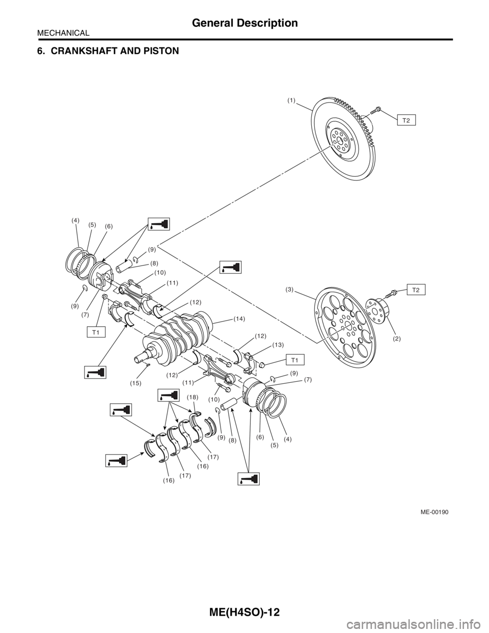
6. CRANKSHAFT AND PISTON
ME-00190
T1
T1
(9)(1)
(16)(17)(16)(17)(6)
(5)(4)(3)
(2) (12) (11) (10)
(7) (9) (9)
(8) (6) (5) (4)
(15)
(18)
(9)
(8) (10) (12)
(11) (7)
(13) (12) (14)
T2
T2