lug nut SUBARU FORESTER 2004 Service Repair Manual
[x] Cancel search | Manufacturer: SUBARU, Model Year: 2004, Model line: FORESTER, Model: SUBARU FORESTER 2004Pages: 2870, PDF Size: 38.67 MB
Page 248 of 2870

SB-14
SEAT BELT SYSTEM
Disposal of Pretensioner
6. Disposal of Pretensioner
A: CAUTION
Do not discard undeployed pretensioners, because
they may cause serious personal injury when acci-
dentally deployed.
Deployment of the pretensioners should be done
on a flat place free from any possible danger. Avoid
deploying outdoors during heavy rainy or strong
windy weather.
Do not drop or damage the pretensioner.
Because deploying the pretensioners causes a
high-explosive noise, be sure to warn people in the
area, and do not allow anyone within a 5 m (16 ft)
radius of the disposal site.
Some smoke will be emitted after deployment of
the pretensioners. Therefore, it must be deployed
in a well-ventilated area with no smoke alarms
nearby.
Wear gloves, goggles, and earplugs during this
operation. Wash your hands afterwards.
After deployment, the pretensioner is especially
hot. Leave it unattended for 40 minutes or longer,
and then discard it.
Do not let water get on the deployed pretension-
er.
Wrap the deployed pretensioner in an airtight vi-
nyl bag, and then discard it.
If circumstances do not permit pretensioner de-
ployment, contact a SUBARU dealer.
B: OPERATION
1. DEPLOYING OF PRETENSIONER WHILE
INSTALLED IN VEHICLE
1) Fold backrest all the way forward, and then
move front seat all the way forward.
2) Turn the ignition switch to OFF, disconnect the
ground cable from battery, and wait for more than
20 seconds before starting work.
3) Remove the center pillar lower trim.
4) Disconnect the connector (A) of pretensioner.
5) Short the terminal to alligator clip furnished as
deployment tool (A).6) Connect the deployment tool and deployment
adapter D (B).
CAUTION:
The deployment tool terminals should be kept
shorted until just before deployment of the pre-
tensioner.
7) Connect the deployment adapter D connector and
pretensioner yellow connector.
8) Extend the deployment tool to the limit, and
make sure that the vehicle is empty. Close all win-
dows, sunroof, and rear gate completely.
9) Move the battery at least 5 m (16 ft) from the ve-
hicle, and secure the nearby area. Connect the de-
ployment tool alligator clip to the battery negative (−
) terminal.
10) Connect the other cable of deployment tool to
the battery positive (+) terminal. Then deploy the
pretensioner.
SB-00129
(A)
(A) Deployment tool: (Tool No. 98299PA030)
(B) Deployment adapter D: (Tool No. 98299SA010)
SB-00021
(A)
(B)
SB-00017
SB-00018
Page 544 of 2870
EB-14
EXTERIOR BODY PANEL
Rear Door Panel
6. Rear Door Panel
A: REMOVAL
1) Disconnect the ground cable from battery.
2) Remove the rear door trim.
3) Remove the rear sealing cover.
4) Remove the rear door glass.
5) Remove the rear door regulator and motor as-
sembly.
6) Remove the rear door latch assembly.
7) Remove the rear outer handle.
8) Remove the center pillar lower trim.
9) Remove the seat belt bracket and blind plug.
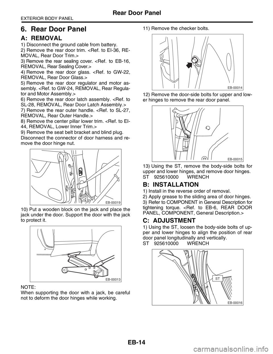
Disconnect the connector of door harness and re-
move the door hinge nut.
10) Put a wooden block on the jack and place the
jack under the door. Support the door with the jack
to protect it.
NOTE:
When supporting the door with a jack, be careful
not to deform the door hinges while working.11) Remove the checker bolts.
12) Remove the door-side bolts for upper and low-
er hinges to remove the rear door panel.
13) Using the ST, remove the body-side bolts for
upper and lower hinges, and remove door hinges.
ST 925610000 WRENCH
B: INSTALLATION
1) Install in the reverse order of removal.
2) Apply grease to the sliding area of door hinges.
3) Refer to COMPONENT in General Description for
tightening torque.
C: ADJUSTMENT
1) Using the ST, loosen the body-side bolts of up-
per and lower hinges to align the position of rear
door panel longitudinally and vertically.
ST 925610000 WRENCH
EB-00019
EB-00013
EB-00014
EB-00015
EB-00016
ST
Page 763 of 2870
PM-26
PERIODIC MAINTENANCE SERVICE
ATF
16.ATF
A: INSPECTION
CAUTION:
The level of ATF varies with fluid temperature.
Pay attention to the fluid temperature when
checking ATF level.
1) Raise the ATF temperature by driving a distance
of 5 to 10 km (3 to 6 miles). Otherwise, idle the en-
gine to raise ATF temperature to 70 — 80°C (158
— 176°F) on Subaru Select Monitor.
TION, Subaru Select Monitor.>
2) Make sure the vehicle is level.
3) After selecting all positions (P, R, N, D, 3, 2, 1),
set the select lever in “P” range. Measure the ATF
level with the engine idling for one or two minutes.
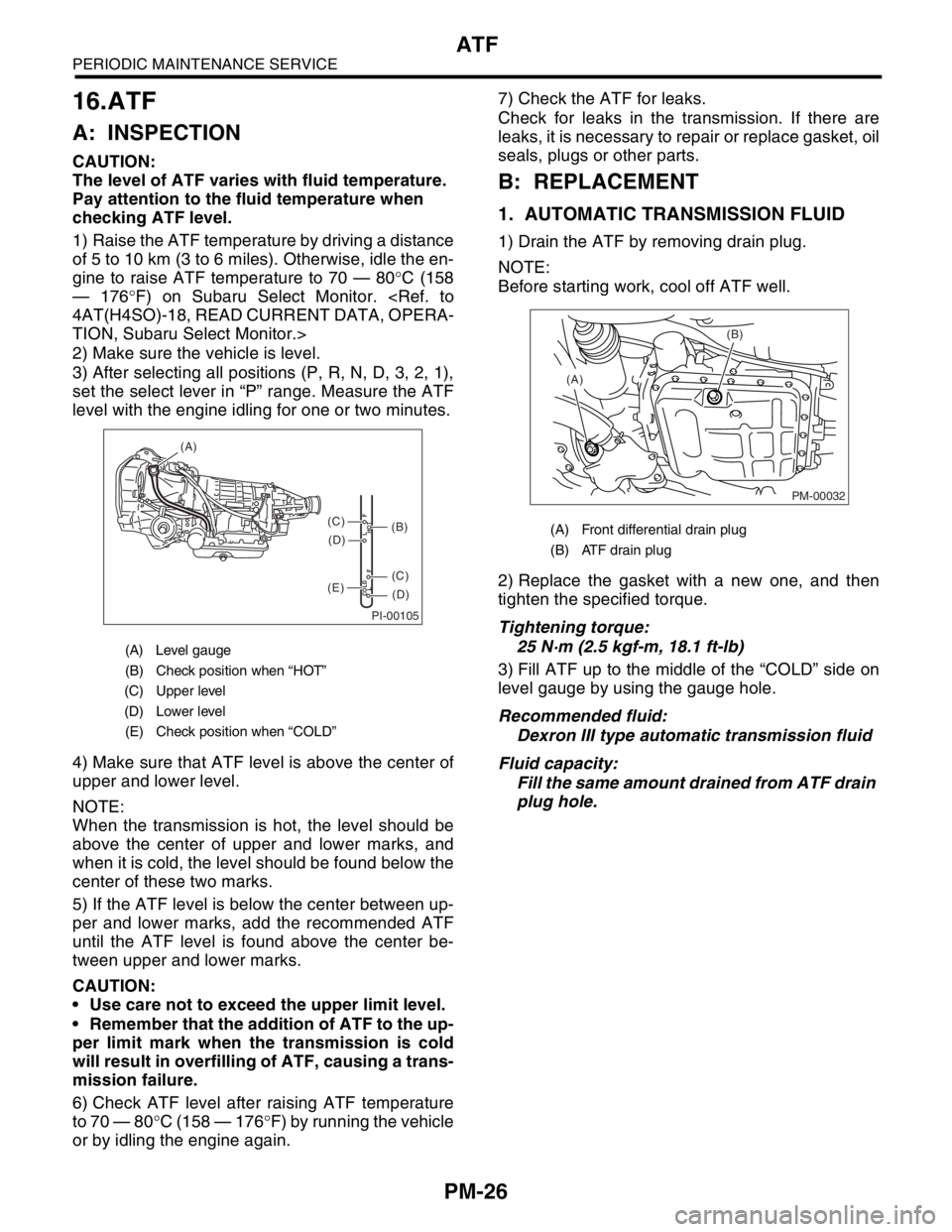
4) Make sure that ATF level is above the center of
upper and lower level.
NOTE:
When the transmission is hot, the level should be
above the center of upper and lower marks, and
when it is cold, the level should be found below the
center of these two marks.
5) If the ATF level is below the center between up-
per and lower marks, add the recommended ATF
until the ATF level is found above the center be-
tween upper and lower marks.
CAUTION:
Use care not to exceed the upper limit level.
Remember that the addition of ATF to the up-
per limit mark when the transmission is cold
will result in overfilling of ATF, causing a trans-
mission failure.
6) Check ATF level after raising ATF temperature
to 70 — 80°C (158 — 176°F) by running the vehicle
or by idling the engine again.7) Check the ATF for leaks.
Check for leaks in the transmission. If there are
leaks, it is necessary to repair or replace gasket, oil
seals, plugs or other parts.
B: REPLACEMENT
1. AUTOMATIC TRANSMISSION FLUID
1) Drain the ATF by removing drain plug.
NOTE:
Before starting work, cool off ATF well.
2) Replace the gasket with a new one, and then
tighten the specified torque.
Tightening torque:
25 N·m (2.5 kgf-m, 18.1 ft-lb)
3) Fill ATF up to the middle of the “COLD” side on
level gauge by using the gauge hole.
Recommended fluid:
Dexron III type automatic transmission fluid
Fluid capacity:
Fill the same amount drained from ATF drain
plug hole.
(A) Level gauge
(B) Check position when “HOT”
(C) Upper level
(D) Lower level
(E) Check position when “COLD”
PI-00105
COLD
LFHOT LF
(A)
(C)
(D)
(C)
(D)
(E)
(B)(A) Front differential drain plug
(B) ATF drain plug
PM-00032
(B)
(A)
Page 833 of 2870
FU(H4SO)-51
FUEL INJECTION (FUEL SYSTEM)
Fuel Filler Pipe
21.Fuel Filler Pipe
A: REMOVAL
WARNING:
Place “NO FIRE” signs near the working area.
Be careful not to spill fuel.
1) Set the vehicle on a lift.
2) Release the fuel pressure.
TION, Fuel.>
3) Open the fuel filler flap lid and remove fuel filler
cap.
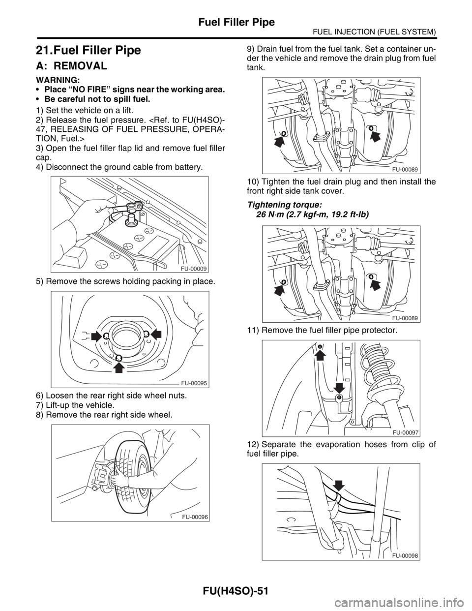
4) Disconnect the ground cable from battery.
5) Remove the screws holding packing in place.
6) Loosen the rear right side wheel nuts.
7) Lift-up the vehicle.
8) Remove the rear right side wheel.9) Drain fuel from the fuel tank. Set a container un-
der the vehicle and remove the drain plug from fuel
tank.
10) Tighten the fuel drain plug and then install the
front right side tank cover.
Tightening torque:
26 N
⋅m (2.7 kgf-m, 19.2 ft-lb)
11) Remove the fuel filler pipe protector.
12) Separate the evaporation hoses from clip of
fuel filler pipe.
FU-00009
FU-00095
FU-00096
FU-00089
FU-00089
FU-00097
FU-00098
Page 895 of 2870
ME(H4SO)-26
MECHANICAL
Idle Speed
3. Idle Speed
A: INSPECTION
1) Before checking idle speed, check the following:
(1) Ensure the air cleaner element is free from
clogging, ignition timing is correct, spark plugs
are in good condition, and the hoses are con-
nected properly.
(2) Ensure the malfunction indicator light does
not illuminate.
2) Warm-up the engine.
3) Stop the engine, and then turn the ignition switch
to OFF.
4) When using the Subaru Select Monitor, refer to
the following.
tion.>
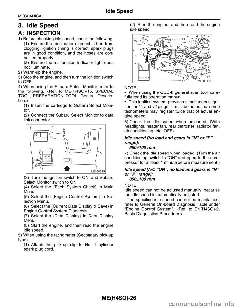
(1) Insert the cartridge to Subaru Select Moni-
tor.
(2) Connect the Subaru Select Monitor to data
link connector.
(3) Turn the ignition switch to ON, and Subaru
Select Monitor switch to ON.
(4) Select the {Each System Check} in Main
Menu.
(5) Select the {Engine Control System} in Se-
lection Menu.
(6) Select the {Current Data Display & Save} in
Engine Control System Diagnosis.
(7) Select the {Data Display} in Data Display
Menu.
(8) Start the engine, and then read the engine
idle speed.
5) When using the tachometer (Secondary pick-up
type).
(1) Attach the pick-up clip to No. 1 cylinder
spark plug cord.(2) Start the engine, and then read the engine
idle speed.
NOTE:
When using the OBD-II general scan tool, care-
fully read its operation manual.
This ignition system provides simultaneous igni-
tion for #1 and #2 plugs. It must be noted that some
tachometers may register twice that of actual en-
gine speed.
6) Check the idle speed when unloaded. (With
headlights, heater fan, rear defroster, radiator fan,
air conditioning, etc. OFF)
Idle speed [No load and gears in “N” or “P”
range]:
650
±100 rpm
7) Check the idle speed when loaded. (Turn the air
conditioning switch to “ON” and operate the com-
pressor for at least 1 minute before measurement.)
Idle speed [A/C “ON”, no load and gears in “N”
or “P” range]:
850
±100 rpm
NOTE:
Idle speed can not be adjusted manually, because
the idle speed is automatically adjusted.
If the specified idle speed can not be maintained,
refer to General On-board Diagnosis Table under
“Engine Control System”.
ME-00325
ME-00193
Page 905 of 2870
ME(H4SO)-36
MECHANICAL
Engine Assembly
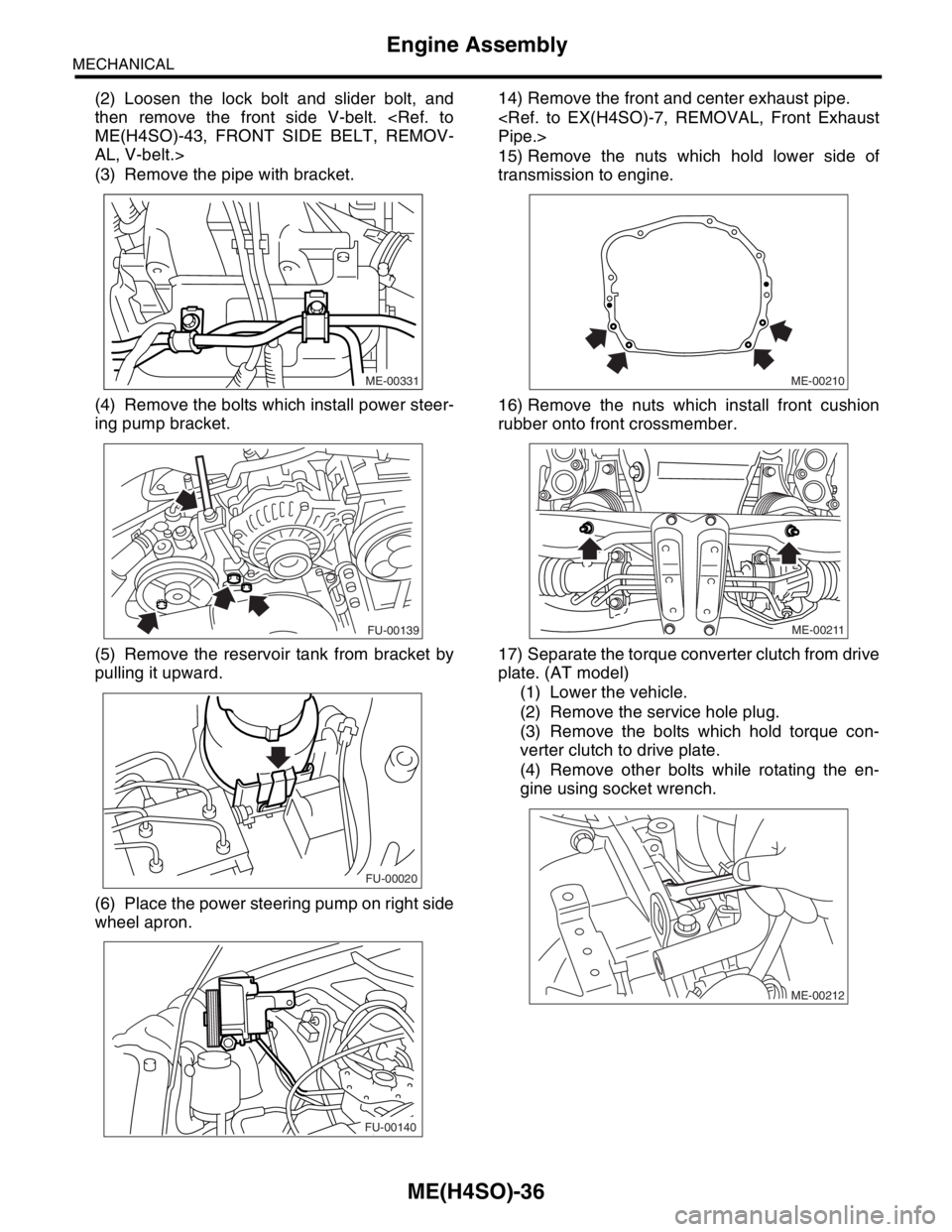
(2) Loosen the lock bolt and slider bolt, and
then remove the front side V-belt.
AL, V-belt.>
(3) Remove the pipe with bracket.
(4) Remove the bolts which install power steer-
ing pump bracket.
(5) Remove the reservoir tank from bracket by
pulling it upward.
(6) Place the power steering pump on right side
wheel apron.14) Remove the front and center exhaust pipe.
15) Remove the nuts which hold lower side of
transmission to engine.
16) Remove the nuts which install front cushion
rubber onto front crossmember.
17) Separate the torque converter clutch from drive
plate. (AT model)
(1) Lower the vehicle.
(2) Remove the service hole plug.
(3) Remove the bolts which hold torque con-
verter clutch to drive plate.
(4) Remove other bolts while rotating the en-
gine using socket wrench.
ME-00331
FU-00139
FU-00020
FU-00140ME-00210
ME-00211
ME-00212
Page 1033 of 2870

LU(H4SO)-5
LUBRICATION
General Description
C: CAUTION
Wear working clothing, including a cap, protec-
tive goggles, and protective shoes during opera-
tion.
Remove contamination including dirt and corro-
sion before removal, installation or disassembly.
Keep the disassembled parts in order and pro-
tect them from dust or dirt.
Before removal, installation or disassembly, be
sure to clarify the failure. Avoid unnecessary re-
moval, installation, disassembly, and replacement.
Be careful not to burn yourself, because each
part in the vehicle is hot after running.
Be sure to tighten fasteners including bolts and
nuts to the specified torque.
Place shop jacks or rigid racks at the specified
points.
Before disconnecting electrical connectors of
sensors or units, be sure to disconnect the ground
cable from battery.
(1) Plug (16) Oil pressure switch (33) O-ring
(2) Gasket (17) Oil filler cap (34) Oil filter connector (model without
oil cooler)
(3) Relief valve spring (18) O-ring
(4) Relief valve (19) Oil filler duct (35) Plug (model without oil cooler)
(5) Oil seal (20) O-ring (36) O-ring
(6) Oil pump case (21) Rocker cover
(7) Inner rotor (22) Oil strainerTightening torque: N
⋅m (kgf-m, ft-lb)
(8) Outer rotor (23) GasketT1: 5 (0.5, 3.6)
(9) Oil pump cover (24) Oil level gauge guideT2: 6.4 (0.65, 4.7)
(10) Oil filter (25) Oil panT3: 10 (1.0, 7.0)
(11) Oil cooler connector (model with
oil cooler)(26) Oil level gaugeT4: 44 (4.5, 32.5)
(27) Metal gasketT5: 69 (7.0, 50.9)
(12) Water by-pass pipe (model with oil
cooler)(28) Drain plugT6: 6.4 (0.65, 4.7)
(29) O-ringT7: 25 (2.5, 18.1)
(13) Oil cooler (model with oil cooler) (30) Adapter (1)T8: 44 (4.5, 32.5)
(14) O-ring (31) Adapter (2)T9: 54 (5.5, 40)
(15) Oil pump ASSY (32) Baffle plate
Page 1038 of 2870
LU(H4SO)-10
LUBRICATION
Engine Oil
3. Engine Oil
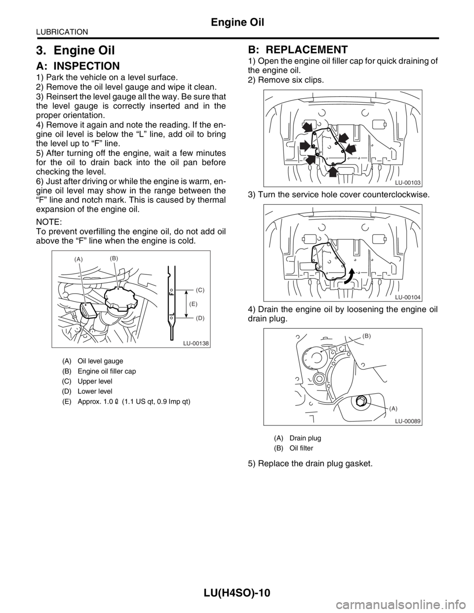
A: INSPECTION
1) Park the vehicle on a level surface.
2) Remove the oil level gauge and wipe it clean.
3) Reinsert the level gauge all the way. Be sure that
the level gauge is correctly inserted and in the
proper orientation.
4) Remove it again and note the reading. If the en-
gine oil level is below the “L” line, add oil to bring
the level up to “F” line.
5) After turning off the engine, wait a few minutes
for the oil to drain back into the oil pan before
checking the level.
6) Just after driving or while the engine is warm, en-
gine oil level may show in the range between the
“F” line and notch mark. This is caused by thermal
expansion of the engine oil.
NOTE:
To prevent overfilling the engine oil, do not add oil
above the “F” line when the engine is cold.
B: REPLACEMENT
1) Open the engine oil filler cap for quick draining of
the engine oil.
2) Remove six clips.
3) Turn the service hole cover counterclockwise.
4) Drain the engine oil by loosening the engine oil
drain plug.
5) Replace the drain plug gasket.
(A) Oil level gauge
(B) Engine oil filler cap
(C) Upper level
(D) Lower level
(E) Approx. 1.02 (1.1 US qt, 0.9 Imp qt)
LU-00138
(A)(B)
(C)
(D) (E)
(A) Drain plug
(B) Oil filter
LU-00103
LU-00104
LU-00089
(B)
(A)
Page 1045 of 2870
LU(H4SO)-17
LUBRICATION
Oil Pan and Strainer
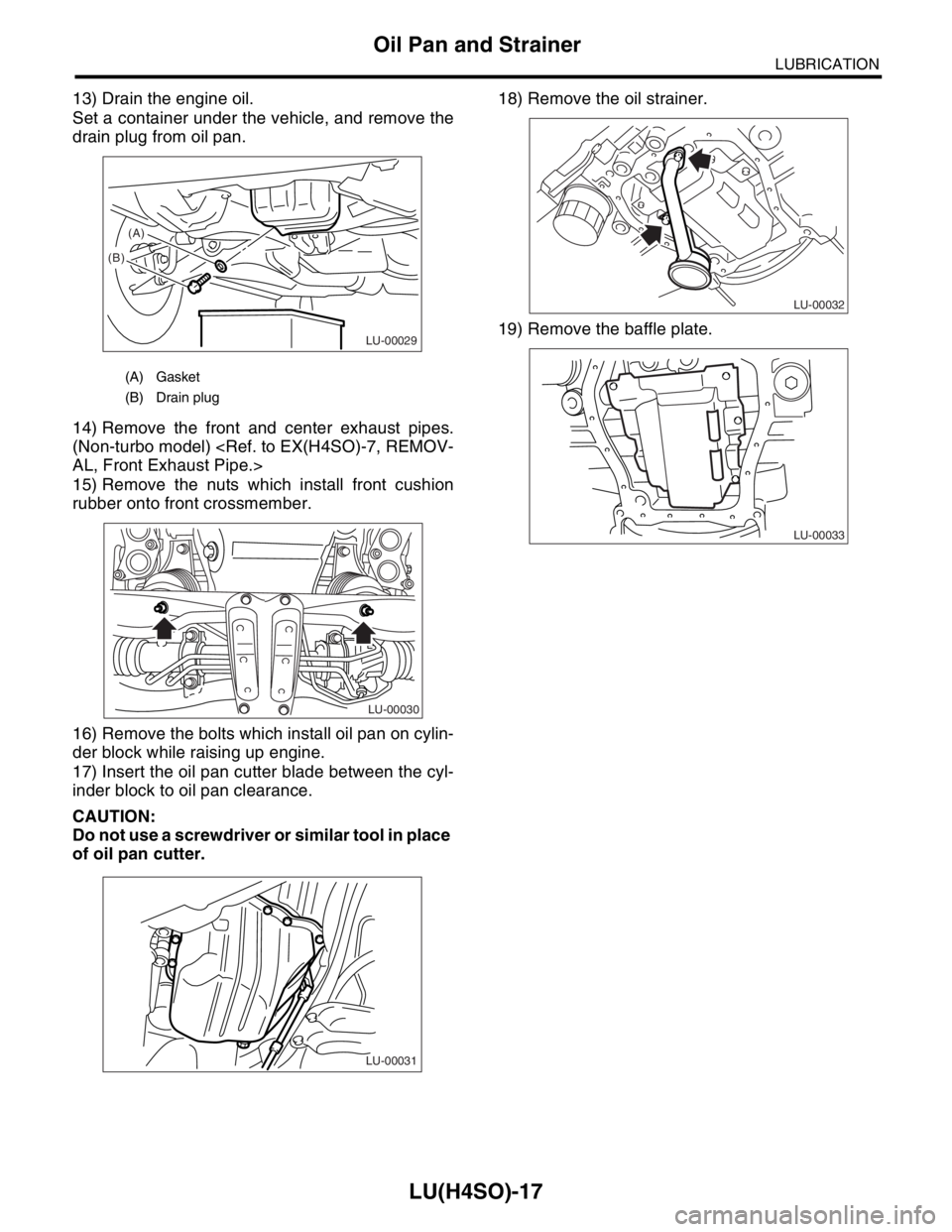
13) Drain the engine oil.
Set a container under the vehicle, and remove the
drain plug from oil pan.
14) Remove the front and center exhaust pipes.
(Non-turbo model)
15) Remove the nuts which install front cushion
rubber onto front crossmember.
16) Remove the bolts which install oil pan on cylin-
der block while raising up engine.
17) Insert the oil pan cutter blade between the cyl-
inder block to oil pan clearance.
CAUTION:
Do not use a screwdriver or similar tool in place
of oil pan cutter.18) Remove the oil strainer.
19) Remove the baffle plate.
(A) Gasket
(B) Drain plug
LU-00029
(B)(A)
LU-00030
LU-00031
LU-00032
LU-00033
Page 1096 of 2870
SC(H4SO)-21
STARTING/CHARGING SYSTEM
Battery
4. Battery
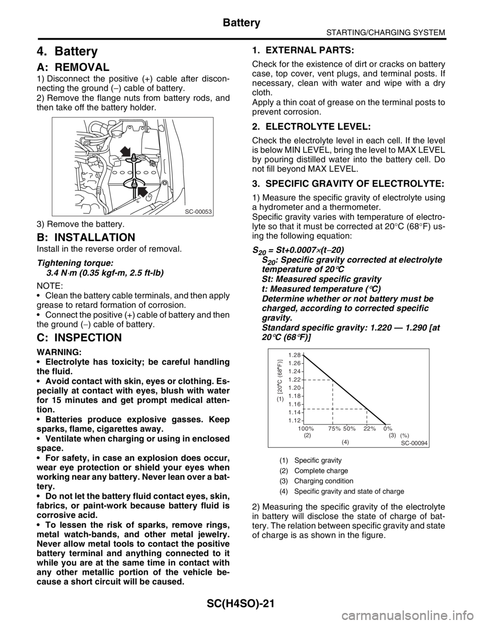
A: REMOVAL
1) Disconnect the positive (+) cable after discon-
necting the ground (−) cable of battery.
2) Remove the flange nuts from battery rods, and
then take off the battery holder.
3) Remove the battery.
B: INSTALLATION
Install in the reverse order of removal.
Tightening torque:
3.4 N
⋅m (0.35 kgf-m, 2.5 ft-lb)
NOTE:
Clean the battery cable terminals, and then apply
grease to retard formation of corrosion.
Connect the positive (+) cable of battery and then
the ground (−) cable of battery.
C: INSPECTION
WARNING:
Electrolyte has toxicity; be careful handling
the fluid.
Avoid contact with skin, eyes or clothing. Es-
pecially at contact with eyes, blush with water
for 15 minutes and get prompt medical atten-
tion.
Batteries produce explosive gasses. Keep
sparks, flame, cigarettes away.
Ventilate when charging or using in enclosed
space.
For safety, in case an explosion does occur,
wear eye protection or shield your eyes when
working near any battery. Never lean over a bat-
tery.
Do not let the battery fluid contact eyes, skin,
fabrics, or paint-work because battery fluid is
corrosive acid.
To lessen the risk of sparks, remove rings,
metal watch-bands, and other metal jewelry.
Never allow metal tools to contact the positive
battery terminal and anything connected to it
while you are at the same time in contact with
any other metallic portion of the vehicle be-
cause a short circuit will be caused.
1. EXTERNAL PARTS:
Check for the existence of dirt or cracks on battery
case, top cover, vent plugs, and terminal posts. If
necessary, clean with water and wipe with a dry
cloth.
Apply a thin coat of grease on the terminal posts to
prevent corrosion.
2. ELECTROLYTE LEVEL:
Check the electrolyte level in each cell. If the level
is below MIN LEVEL, bring the level to MAX LEVEL
by pouring distilled water into the battery cell. Do
not fill beyond MAX LEVEL.
3. SPECIFIC GRAVITY OF ELECTROLYTE:
1) Measure the specific gravity of electrolyte using
a hydrometer and a thermometer.
Specific gravity varies with temperature of electro-
lyte so that it must be corrected at 20°C (68°F) us-
ing the following equation:
S
20 = St+0.0007×(t−20)
S
20: Specific gravity corrected at electrolyte
temperature of 20
°C
St: Measured specific gravity
t: Measured temperature (
°C)
Determine whether or not battery must be
charged, according to corrected specific
gravity.
Standard specific gravity: 1.220 — 1.290 [at
20
°C (68°F)]
2) Measuring the specific gravity of the electrolyte
in battery will disclose the state of charge of bat-
tery. The relation between specific gravity and state
of charge is as shown in the figure.
SC-00053
(1) Specific gravity
(2) Complete charge
(3) Charging condition
(4) Specific gravity and state of charge
1.28
1.26
1.24
1.22
1.20
1.18
1.16
1.14
1.12
100%
(%)75% 50% 22% 0%
SC-00094
[20 C (68 F)](1)
(2) (3)
(4)