length SUBARU FORESTER 2004 Service Repair Manual
[x] Cancel search | Manufacturer: SUBARU, Model Year: 2004, Model line: FORESTER, Model: SUBARU FORESTER 2004Pages: 2870, PDF Size: 38.67 MB
Page 4 of 2870

AC-2
HVAC SYSTEM (HEATER, VENTILATOR AND A/C)
General Description
1. General Description
A: SPECIFICATION
1. HEATER SYSTEM
2. A/C SYSTEM
AUTO A/C MODEL
Item Specifications Condition
Heating capacity5.0 kW (4,300 kcal/h,
17,062 BTU/h) or more• Mode selector switch: HEAT
• Temperature control switch: FULL HOT
• Temperature difference between hot water
and inlet air: 65°C (149°F)
• Hot water flow rate: 3602 (95.1 US gal, 79.2
Imp gal)/h
Air flow rate
280 m
3 (9,888 cu ft)/hHeat mode (FRESH), FULL HOT at 12.5 V
Max air flow rate
480 m
3 (16,951 cu ft)/h• Temperature control switch: FULL COLD
• Blower fan speed: 4th position
• Mode selector lever: RECIRC
Heater core size
(height×length×width)134.1×224.3×32 mm
(5.28×8.83×1.26 in)—
Blower motorTy p eAuto A/C (Brushless motor)
230 W or less12.5 V
Manual A/C (Cylinder motor)
260 W or less12.5 V
Fan type and size
(diameter×width)Sirocco fan type
150×75 mm (5.91×2.95 in)—
Item Specifications
Type of air conditioner Reheat air-mix type
Cooling capacity5.1 kW
(4,386 kcal/h, 17,403 BTU/h)
RefrigerantHFC-134a (CH
2FCF3)
[0.6±0.05 kg (1.32±0.11 lb)]
CompressorType Vane rotary, fix volume (DKV-14G)
Discharge
140 cm
3 (8.54 cu in)/rev
Max. permissible speed 7,000 rpm
Magnet clutchType Dry, single-disc type
Power consumption 38 W (DC 12 V-25°C)
Type of belt V-belt 4 PK
Pulley dia. (effective dia.) 125 mm (4.92 in)
Pulley ratio 1.064
CondenserType Corrugated fin (Sub cool type)
Core face area
0.234 m
2 (2.52 sq ft)
Core thickness 16 mm (0.63 in)
Radiation area
5.6 m
2 (62.28 sq ft)
Receiver drier Effective inner capacity
220 cm
3 (13.42 cu in)
Expansion valve Type External equalizing
EvaporatorType Single tank
Dimensions (W×H×T)176.5×266×60 mm
(6.95×10.47×2.36 in)
Blower fanFan type Sirocco fan
Outer diameter×width 150×75 mm (5.91×2.95 in)
Power consumption 230 W or less at 12.5 V
Page 32 of 2870
AC-30
HVAC SYSTEM (HEATER, VENTILATOR AND A/C)
Refrigerant Leak Check
5. Refrigerant Leak Check
A: INSPECTION
1) Operate the A/C system for approx. 10 minutes,
and confirm that the high-pressure side shows at
least 690 kPa (7.03 kg/cm
2, 100 psi). Then stop the
engine to start the leak test.
2) Starting from the connection between the high-
pressure pipe and evaporator, check the system for
leaks along the high-pressure side through the
compressor. The following items must be checked
thoroughly.
3) Check the joint and seam between the pressure
switch (triple pressure switch) and high-pressure
pipe.
4) Check the connections between the condenser
and pipes, and welded joints on the condenser.
The leak tester may detect the oil on the condenser
fins as a leak.
5) Check the joint between the compressor and
hoses.
6) Check the machined area of compressor and
other joints on the compressor.
7) Check the compressor shaft seal at the area
near the center of compressor clutch pulley.
Some shaft seals show a slight amount of leakage
about 28 g (1.0 oz) per year. This is not a problem.
8) Starting from the connection between the low-
pressure pipe and evaporator, check the system for
leakage along the low-pressure side through the
compressor. The following items must be checked
thoroughly.
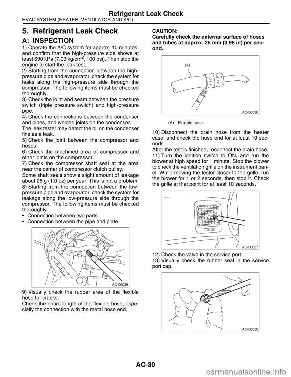
Connection between two parts
Connection between the pipe and plate
9) Visually check the rubber area of the flexible
hose for cracks.
Check the entire length of the flexible hose, espe-
cially the connection with the metal hose end.CAUTION:
Carefully check the external surface of hoses
and tubes at approx. 25 mm (0.98 in) per sec-
ond.
10) Disconnect the drain hose from the heater
case, and check the hose end for at least 10 sec-
onds.
After the test is finished, reconnect the drain hose.
11) Turn the ignition switch to ON, and run the
blower at high speed for 1 minute. Stop the blower
to check the ventilation grille on the instrument pan-
el. While moving the tester closer to the grille, run
the blower for 1 or 2 seconds, then stop it. Check
the grille at that point for at least 10 seconds.
12) Check the valve in the service port.
13) Visually check the rubber seal in the service
port cap.
AC-00035
(A) Flexible hose
AC-00036
(A)
AC-00037
AC-00038
Page 113 of 2870
AB-13
AIRBAG SYSTEM
Inspection Locations After a Collision
5. FRONT SUB SENSOR
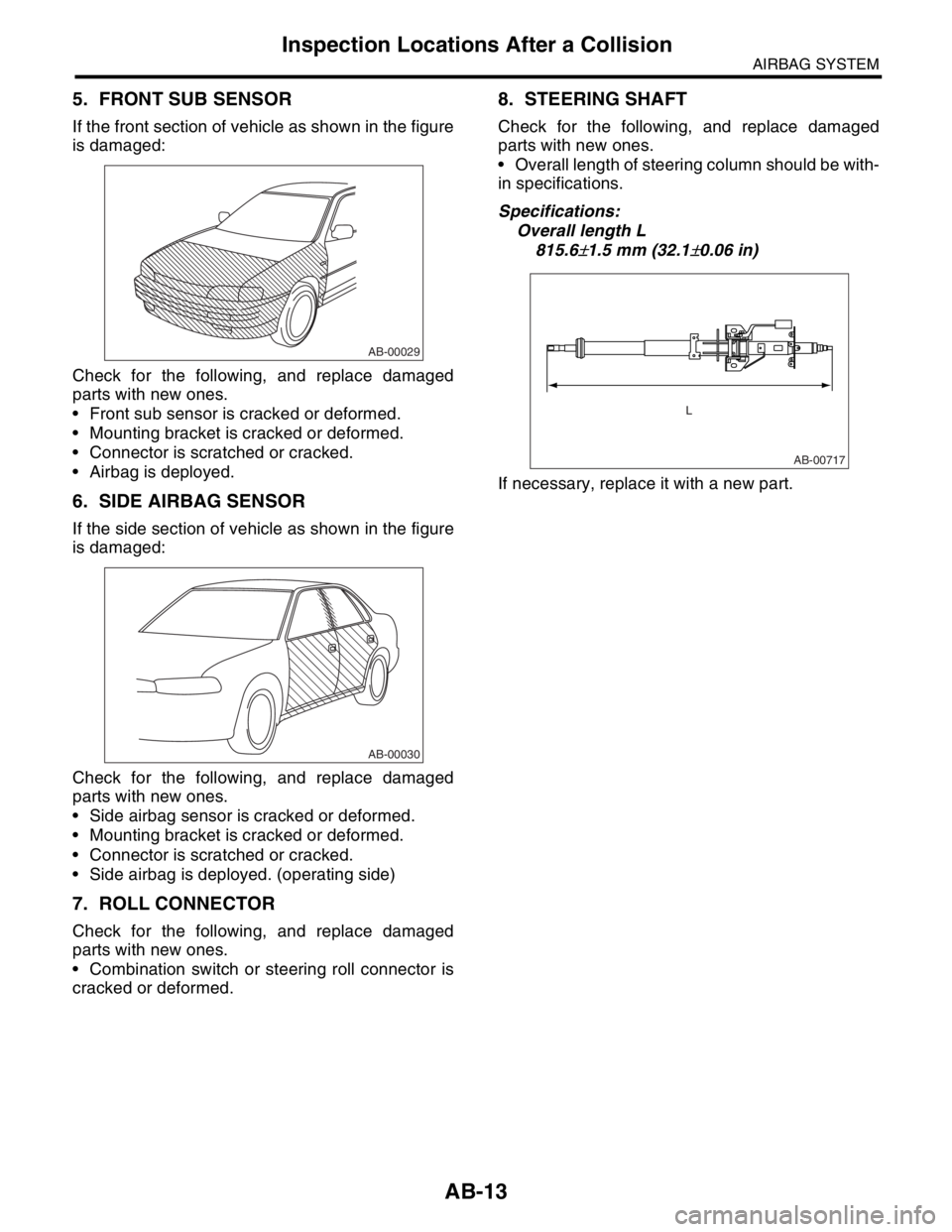
If the front section of vehicle as shown in the figure
is damaged:
Check for the following, and replace damaged
parts with new ones.
Front sub sensor is cracked or deformed.
Mounting bracket is cracked or deformed.
Connector is scratched or cracked.
Airbag is deployed.
6. SIDE AIRBAG SENSOR
If the side section of vehicle as shown in the figure
is damaged:
Check for the following, and replace damaged
parts with new ones.
Side airbag sensor is cracked or deformed.
Mounting bracket is cracked or deformed.
Connector is scratched or cracked.
Side airbag is deployed. (operating side)
7. ROLL CONNECTOR
Check for the following, and replace damaged
parts with new ones.
Combination switch or steering roll connector is
cracked or deformed.
8. STEERING SHAFT
Check for the following, and replace damaged
parts with new ones.
Overall length of steering column should be with-
in specifications.
Specifications:
Overall length L
815.6
±1.5 mm (32.1±0.06 in)
If necessary, replace it with a new part.
AB-00029
AB-00030
AB-00717
L
Page 268 of 2870
LI-14
LIGHTING SYSTEM
Headlight Assembly
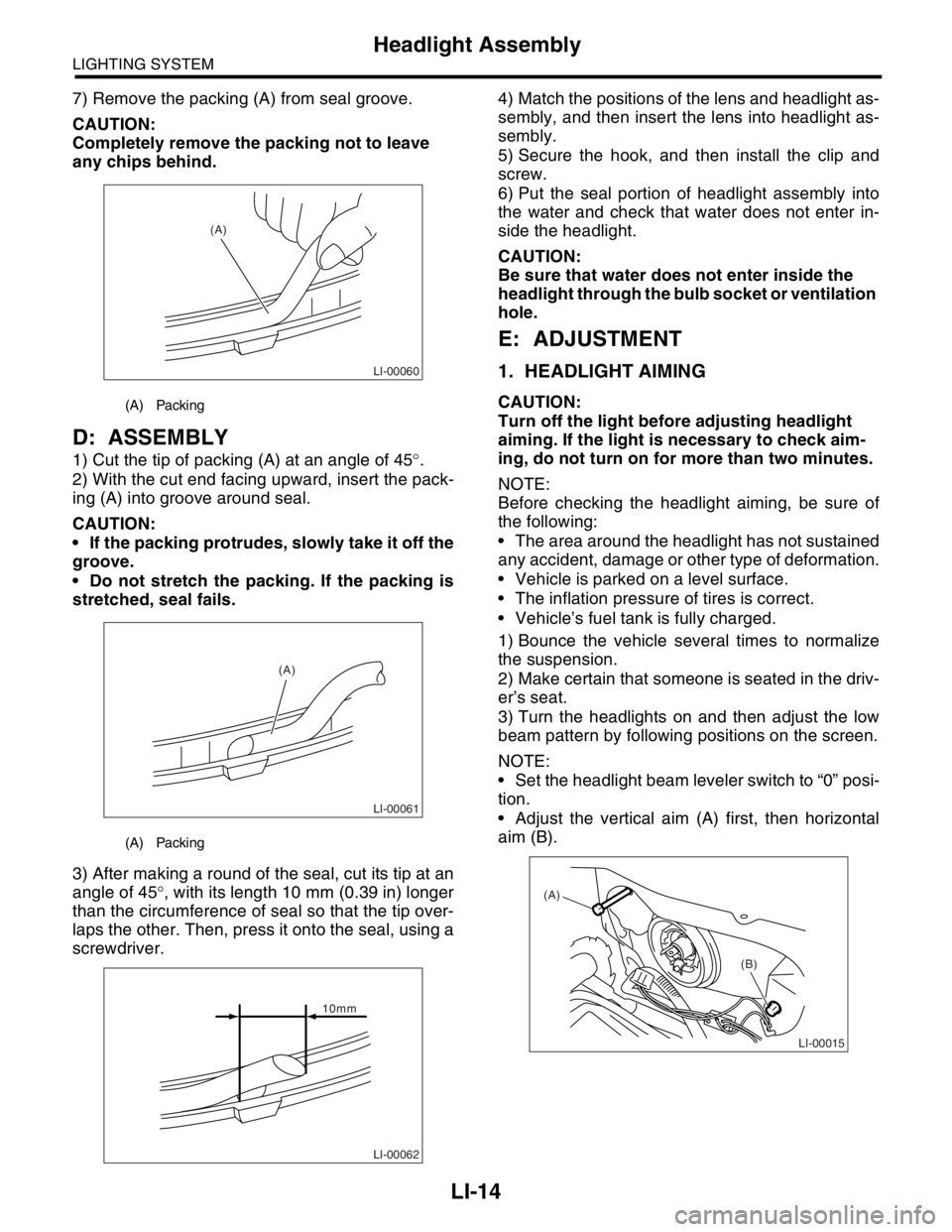
7) Remove the packing (A) from seal groove.
CAUTION:
Completely remove the packing not to leave
any chips behind.
D: ASSEMBLY
1) Cut the tip of packing (A) at an angle of 45°.
2) With the cut end facing upward, insert the pack-
ing (A) into groove around seal.
CAUTION:
If the packing protrudes, slowly take it off the
groove.
Do not stretch the packing. If the packing is
stretched, seal fails.
3) After making a round of the seal, cut its tip at an
angle of 45°, with its length 10 mm (0.39 in) longer
than the circumference of seal so that the tip over-
laps the other. Then, press it onto the seal, using a
screwdriver.4) Match the positions of the lens and headlight as-
sembly, and then insert the lens into headlight as-
sembly.
5) Secure the hook, and then install the clip and
screw.
6) Put the seal portion of headlight assembly into
the water and check that water does not enter in-
side the headlight.
CAUTION:
Be sure that water does not enter inside the
headlight through the bulb socket or ventilation
hole.
E: ADJUSTMENT
1. HEADLIGHT AIMING
CAUTION:
Turn off the light before adjusting headlight
aiming. If the light is necessary to check aim-
ing, do not turn on for more than two minutes.
NOTE:
Before checking the headlight aiming, be sure of
the following:
The area around the headlight has not sustained
any accident, damage or other type of deformation.
Vehicle is parked on a level surface.
The inflation pressure of tires is correct.
Vehicle’s fuel tank is fully charged.
1) Bounce the vehicle several times to normalize
the suspension.
2) Make certain that someone is seated in the driv-
er’s seat.
3) Turn the headlights on and then adjust the low
beam pattern by following positions on the screen.
NOTE:
Set the headlight beam leveler switch to “0” posi-
tion.
Adjust the vertical aim (A) first, then horizontal
aim (B).(A) Packing
(A) Packing
LI-00060
(A)
LI-00061
(A)
LI-00062
10mm
LI-00015
(A)
(B)
Page 470 of 2870

SR-6
SUNROOF/T-TOP/CONVERTIBLE TOP (SUNROOF)
Sunroof Assembly
4. Sunroof Assembly
A: REMOVAL
1) Disconnect the ground cable from battery.
2) Remove roof trim.
3) Remove sunroof lid.
4) Disconnect the four drain tubes (A) from sunroof
frame.
5) Disconnect sunroof harness connector.
6) Remove the bolts, and then remove the frame
bracket.
7) Remove bolts and nuts and then detach sunroof
frame.
B: INSTALLATION
Install in the reverse order of removal.
CAUTION:
Be careful not to snag harness.
NOTE:
Make sure to connect harness connector.
When installing drain tube, insert it securely into
drain pipe.
Length A:
15 mm (0.59 in) or more
C: DISASSEMBLY
1) Remove sunroof frame.
2) Cut the pawl (A) of front sunshade RH.
3) Remove the front slider RH.
4) Pull out the sunshade (B) from sunroof frame.
D: ASSEMBLY
Assemble in the reverse order of disassembly.
SR-00014
SR-00015(A)(A)
SR-00005
A
SR-00006
(A)
SR-00007
Page 503 of 2870
EI-27
EXTERIOR/INTERIOR TRIM
Front Bumper
3) Deep damage such as a break or hole that requires filling
Much of the peripheral grained surface must be sacrificed for repair, and the degree of restoration is not really
worth the expense. (The surface, however, will become almost flush with adjacent areas.)
Recommended repair kit: PP Part Repair Kit (NRM)
Pro-
cess
No.Process name Job contents
1 Bumper removal Remove the bumper as required.
2 Part removal Remove the parts built into bumper as required.
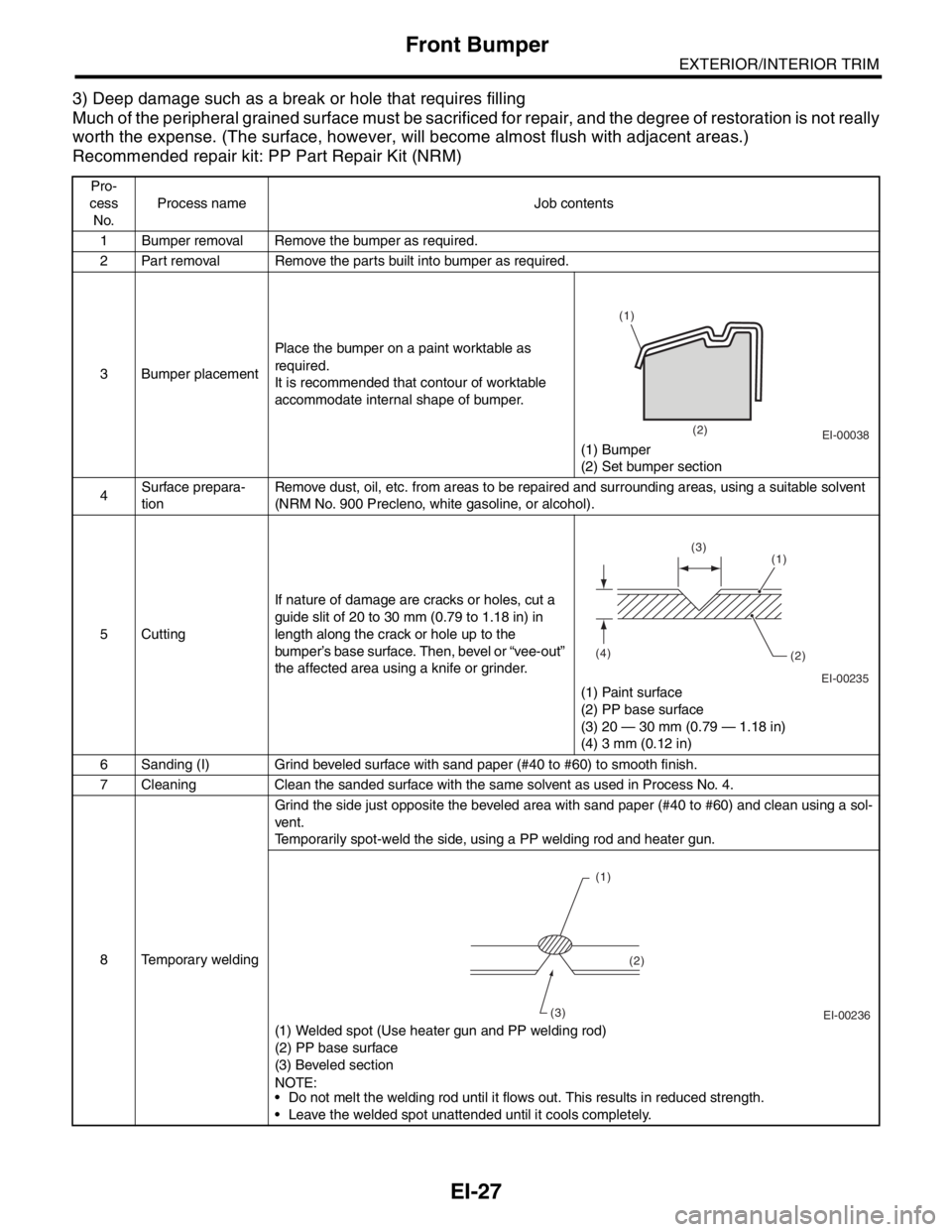
3 Bumper placementPlace the bumper on a paint worktable as
required.
It is recommended that contour of worktable
accommodate internal shape of bumper.
(1) Bumper
(2) Set bumper section
4Surface prepara-
tionRemove dust, oil, etc. from areas to be repaired and surrounding areas, using a suitable solvent
(NRM No. 900 Precleno, white gasoline, or alcohol).
5 CuttingIf nature of damage are cracks or holes, cut a
guide slit of 20 to 30 mm (0.79 to 1.18 in) in
length along the crack or hole up to the
bumper’s base surface. Then, bevel or “vee-out”
the affected area using a knife or grinder.
(1) Paint surface
(2) PP base surface
(3) 20 — 30 mm (0.79 — 1.18 in)
(4) 3 mm (0.12 in)
6 Sanding (I) Grind beveled surface with sand paper (#40 to #60) to smooth finish.
7 Cleaning Clean the sanded surface with the same solvent as used in Process No. 4.
8 Temporary weldingGrind the side just opposite the beveled area with sand paper (#40 to #60) and clean using a sol-
vent.
Temporarily spot-weld the side, using a PP welding rod and heater gun.
(1) Welded spot (Use heater gun and PP welding rod)
(2) PP base surface
(3) Beveled section
N
OTE:
Do not melt the welding rod until it flows out. This results in reduced strength.
Leave the welded spot unattended until it cools completely.
EI-00038
(1)
(2)
EI-00235 (4)
(2) (1) (3)
EI-00236 (1)
(2)
(3)
Page 691 of 2870

SPC-2
SPECIFICATION
Forester
1. Forester
A: DIMENSIONS
★: With sunroof
B: ENGINE
Model 2.0 L Non-turbo 2.0 L Turbo 2.5 L Non-turbo 2.5 L Turbo
Overall length mm (in) 4,450 (175.2)
Overall width mm (in) 1,735 (68.3)
Overall height (at C.W.) mm (in) 1,590 (62.6) 1,585 (62.4) 1,590 (62.6)
CompartmentLength mm (in) 1,795 (70.7)
Width mm (in) 1,455 (57.3)
Height mm (in)
1,245 (49.0), 1,210 (47.6)
★
Wheelbase mm (in) 2,525 (99.4)
Tread Front mm (in) 1,495 (58.9)
Rear mm (in) 1,485 (58.5)
Minimum road clearance mm (in) 190 (7.5) 195 (7.7) 200 (7.9)
Model 2.0 L Non-turbo 2.0 L Turbo 2.5 L Non-turbo 2.5 L Turbo
Engine type Horizontally opposed, liquid cooled, 4-cylinder, 4-stroke gasoline engine
Valve arrangement Overhead camshaft type
Bore×Stroke mm (in) 92×75 (3.62×2.95) 99.5×79 (3.92×3.11)
Displacement
cm
3 (cu in)1,994 (121.67) 2,457 (149.94)
Compression ratio 10.0±0.2 8.0±0.2 10.0±0.2 8.2±0.2
Firing order 1 — 3 — 2 — 4
Idle speed at Park or Neu-
tral positionrpm 650±100 700±100 650±100 700±100
Maximum output kW (PS)/rpm 92 (125)/5,600 130 (177)/5,600 115 (156)/5,600 155 (211)/5,600
Maximum torque N⋅m (kgf-m, ft-lb)/rpm184 (18.8, 41.4)/
3,600245 (25.0, 55.1)/
3,200223 (22.7, 50.1)/
3,600320 (32.6, 71.8)/
3,600
Page 847 of 2870
FU(H4SO)-65
FUEL INJECTION (FUEL SYSTEM)
Fuel Delivery, Return and Evaporation Lines
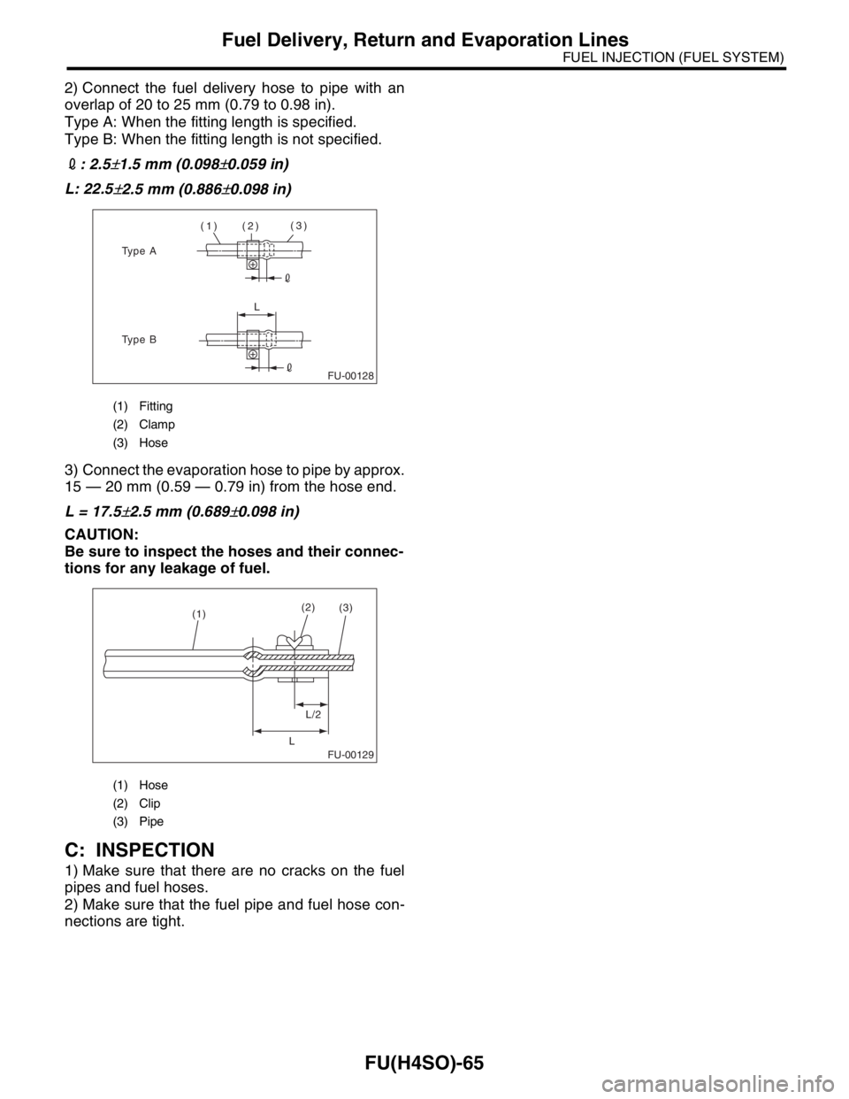
2) Connect the fuel delivery hose to pipe with an
overlap of 20 to 25 mm (0.79 to 0.98 in).
Type A: When the fitting length is specified.
Type B: When the fitting length is not specified.
2: 2.5
±1.5 mm (0.098±0.059 in)
L: 22.5
±2.5 mm (0.886±0.098 in)
3) Connect the evaporation hose to pipe by approx.
15 — 20 mm (0.59 — 0.79 in) from the hose end.
L = 17.5
±2.5 mm (0.689±0.098 in)
CAUTION:
Be sure to inspect the hoses and their connec-
tions for any leakage of fuel.
C: INSPECTION
1) Make sure that there are no cracks on the fuel
pipes and fuel hoses.
2) Make sure that the fuel pipe and fuel hose con-
nections are tight.
(1) Fitting
(2) Clamp
(3) Hose
(1) Hose
(2) Clip
(3) Pipe
FU-00128
(1) (2)(3)
L
Type A
Type B
FU-00129
(1)(2)
L/2
L(3)
Page 872 of 2870

ME(H4SO)-3
MECHANICAL
General Description
Cylinder
headSurface warpage limit (mating with cylinder block) mm (in) 0.05 (0.0020)
Grinding limit mm (in) 0.1 (0.004)
Standard height mm (in) 97.5 (3.84)
Va l ve s e a tRefacing angle90°
Contacting width mm (in)IntakeSTD 1.1 (0.043)
Limit 1.8 (0.070)
ExhaustSTD 1.5 (0.059)
Limit 2.2 (0.087)
Valve guideInner diameter mm (in) 6.000 — 6.012 (0.2362 — 0.2367)
Protrusion above head mm (in)Intake 20.0 — 20.5 (0.787 — 0.807)
Exhaust 16.5 — 17.0 (0.650 — 0.669)
Va l veHead edge thickness mm (in)IntakeSTD 1.0 (0.039)
Limit 0.6 (0.024)
ExhaustSTD 1.2 (0.047)
Limit 0.6 (0.024)
Stem outer diameter mm (in)Intake 5.950 — 5.965 (0.2343 — 0.2348)
Exhaust 5.945 — 5.960(0.2341 — 0.2346)
Stem oil clearance mm (in)STDIntake 0.035 — 0.062 (0.0014 — 0.0024)
Exhaust 0.040 — 0.067 (0.0016 — 0.0026)
Limit — 0.15 (0.0059)
Overall length mm (in)Intake 120.6 (4.75)
Exhaust 121.7 (4.79)
Valve springFree length mm (in) 54.30 (2.1378)
Squareness mm (in) 2.5°, 2.4 (0.094)
Tension/spring height N (kgf, lb)/mm (in)Set214 — 246 (22 — 25, 48 — 55)/
45.0 (1.772)
Lift526 — 582 (54 — 59, 119 — 130)/
34.7 (1.366)
Cylinder
blockSurface warpage limit (mating with cylinder head) mm (in) 0.05 (0.0020)
Grinding limit mm (in) 0.1 (0.004)
Cylinder inner
diametermm (in)2.0 L STDA 92.005 — 92.015 (3.6222 — 3.6226)
B 91.995 — 92.005 (3.6218 — 3.6222)
2.5 L STDA 99.505 — 99.515 (3.9175 — 3.9179)
B 99.495 — 99.505 (3.9171 — 3.9175)
Ta p e r m m ( i n )STD 0.015 (0.0006)
Limit 0.050 (0.0020)
Out-of-roundness mm (in)STD 0.010 (0.0004)
Limit 0.050 (0.0020)
Piston clearance mm (in)STD 0.010 — 0.030 (0.0004 — 0.0012)
Limit 0.050 (0.0020)
Boring mm (in) 0.5 (0.020)
PistonOuter diameter mm (in)2.0 LSTDA 91.985 — 91.995 (3.6214 — 3.6218)
B 91.975 — 91.985 (3.6211 — 3.6214)
0.25 (0.0098) OS 92.225 — 92.235 (3.6309 — 3.6313)
0.50 (0.0197) OS 92.475 — 92.485 (3.6407 — 3.6411)
2.5 LSTDA 99.485 — 99.495 (3.9167 — 3.9171)
B 99.475 — 99.485 (3.9163 — 3.9167)
0.25 (0.0098) OS 99.725 — 99.735 (3.9262 — 3.9266)
0.50 (0.0197) OS 99.975 — 99.985 (3.9360 — 3.9364)
Piston pin standard diameter mm (in) 23.000 — 23.006 (0.9055 — 0.9057)
Page 873 of 2870

ME(H4SO)-4
MECHANICAL
General Description
Piston pinOuter diameter mm (in) 22.994 — 23.000 (0.9053 — 0.9055)
Standard clearance between piston and piston pin mm (in) 0.004 — 0.008 (0.0002 — 0.0003)
Degree of fitPiston pin must be fitted into position with
thumb at 20°C (68°F).
Piston ringRing closed gap mm (in)Top ringSTD 0.20 — 0.35 (0.0079 — 0.0138)
Limit 1.0 (0.039)
Second
ring2.0 LSTD 0.35 — 0.50 (0.0138 — 0.0197)
Limit 1.0 (0.039)
2.5 LSTD 0.37 — 0.52 (0.0146 — 0.0204)
Limit 1.0 (0.039)
Oil ringSTD 0.20 — 0.50 (0.0079 — 0.0197)
Limit 1.5 (0.059)
Ring groove gap mm (in)Top ringSTD 0.040 — 0.080 (0.0016 — 0.0031)
Limit 0.15 (0.0059)
Second
ringSTD 0.030 — 0.070 (0.0012 — 0.0028)
Limit 0.15 (0.0059)
Connecting
rodBend or twist per 100 mm
(3.94 in) in lengthmm (in) Limit 0.10 (0.0039)
Side clearance at large end mm (in)STD 0.070 — 0.330 (0.0028 — 0.0130)
Limit 0.4 (0.016)
Connecting
rod bearingOil clearance mm (in)STD 0.0158 — 0.0438 (0.0006 — 0.0017)
Limit 0.05 (0.0020)
Thickness at cen-
ter portionmm (in)2.0 LSTD 1.492 — 1.501 (0.0587 — 0.0591)
0.03 (0.0012) US 1.510 — 1.513 (0.0594 — 0.0596)
0.05 (0.0020) US 1.520 — 1.523 (0.0598 — 0.0600)
0.25 (0.0098) US 1.620 — 1.623 (0.0638 — 0.0639)
2.5 LSTD 1.492 — 1.503 (0.0587 — 0.0591)
0.03 (0.0012) US 1.510 — 1.513 (0.0594 — 0.0596)
0.05 (0.0020) US 1.520 — 1.523 (0.0598 — 0.0600)
0.25 (0.0098) US 1.620 — 1.623 (0.0638 — 0.0639)
Connecting
rod bushingClearance between piston pin
and bushingmm (in)STD 0 — 0.022 (0 — 0.0009)
Limit 0.030 (0.0012)