rear SUBARU FORESTER 2004 Service Repair Manual
[x] Cancel search | Manufacturer: SUBARU, Model Year: 2004, Model line: FORESTER, Model: SUBARU FORESTER 2004Pages: 2870, PDF Size: 38.67 MB
Page 15 of 2870
AC-13
HVAC SYSTEM (HEATER, VENTILATOR AND A/C)
General Description
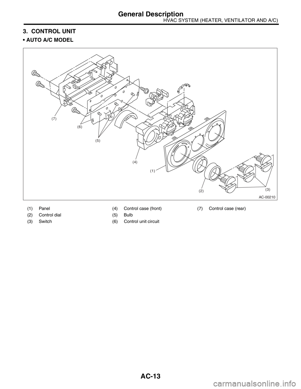
3. CONTROL UNIT
AUTO A/C MODEL
(1) Panel (4) Control case (front) (7) Control case (rear)
(2) Control dial (5) Bulb
(3) Switch (6) Control unit circuit
AC-00210
(7)
(6)
(5)
(4)
(1)
(2)(3)
Page 16 of 2870
AC-14
HVAC SYSTEM (HEATER, VENTILATOR AND A/C)
General Description
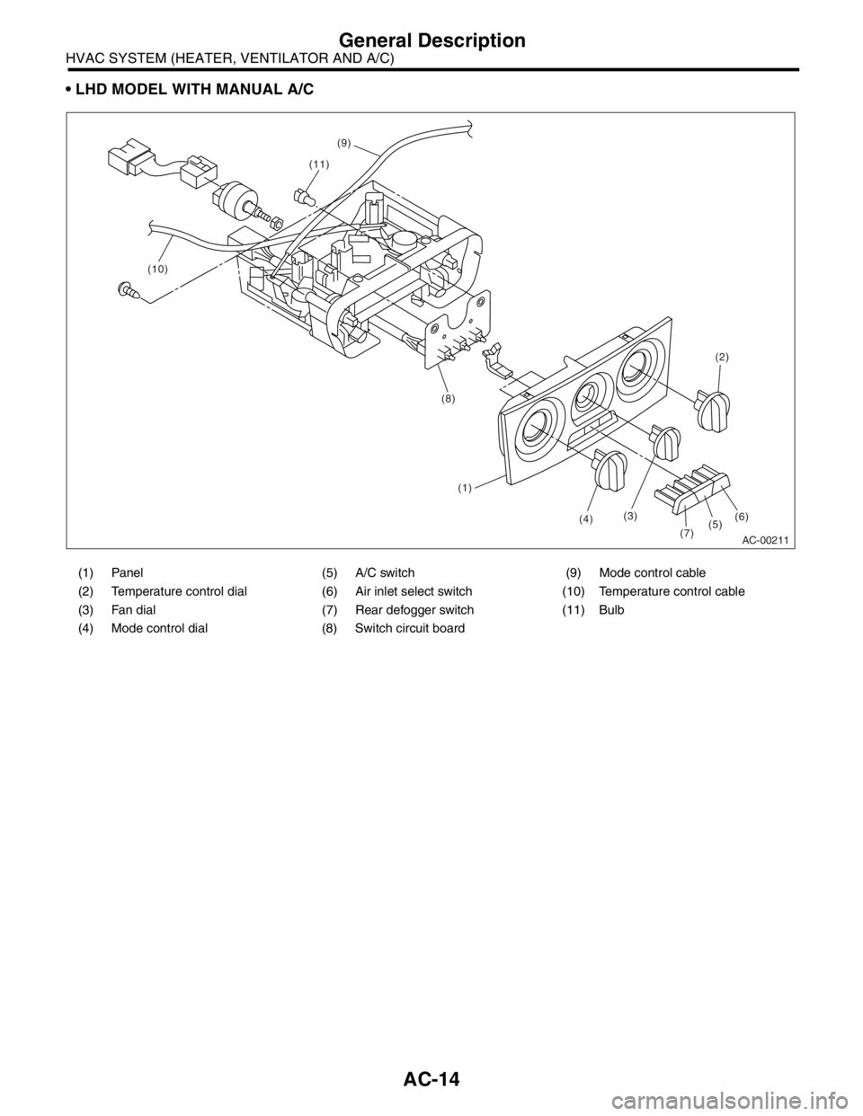
LHD MODEL WITH MANUAL A/C
(1) Panel (5) A/C switch (9) Mode control cable
(2) Temperature control dial (6) Air inlet select switch (10) Temperature control cable
(3) Fan dial (7) Rear defogger switch (11) Bulb
(4) Mode control dial (8) Switch circuit board
AC-00211
(2)
(6)
(5)(7)
(4)(3)
(1)
(8)
(10)
(9)
(11)
Page 17 of 2870
AC-15
HVAC SYSTEM (HEATER, VENTILATOR AND A/C)
General Description
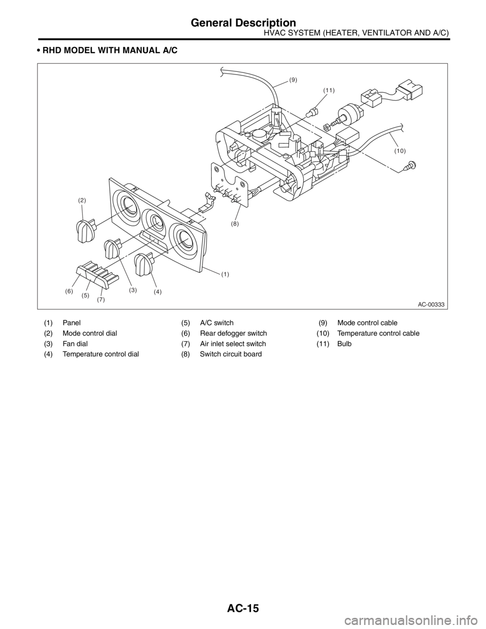
RHD MODEL WITH MANUAL A/C
(1) Panel (5) A/C switch (9) Mode control cable
(2) Mode control dial (6) Rear defogger switch (10) Temperature control cable
(3) Fan dial (7) Air inlet select switch (11) Bulb
(4) Temperature control dial (8) Switch circuit board
AC-00333
(2)
(6)
(5)(7)(4)(3)
(1)
(8)
(10)
(9)
(11)
Page 21 of 2870
AC-19
HVAC SYSTEM (HEATER, VENTILATOR AND A/C)
General Description
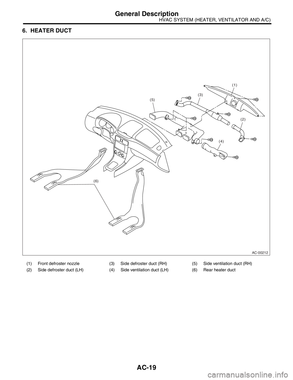
6. HEATER DUCT
(1) Front defroster nozzle (3) Side defroster duct (RH) (5) Side ventilation duct (RH)
(2) Side defroster duct (LH) (4) Side ventilation duct (LH) (6) Rear heater duct
AC-00212
(1)
(3)
(5)
(6)
(2)
(4)
Page 37 of 2870
AC-35
HVAC SYSTEM (HEATER, VENTILATOR AND A/C)
Control Unit
10.Control Unit
A: REMOVAL
1) Disconnect the ground cable from battery.
2) In case of manual A/C, remove the mode cable
and air-mix cable from links of heater unit.
3) Remove the console front cover.
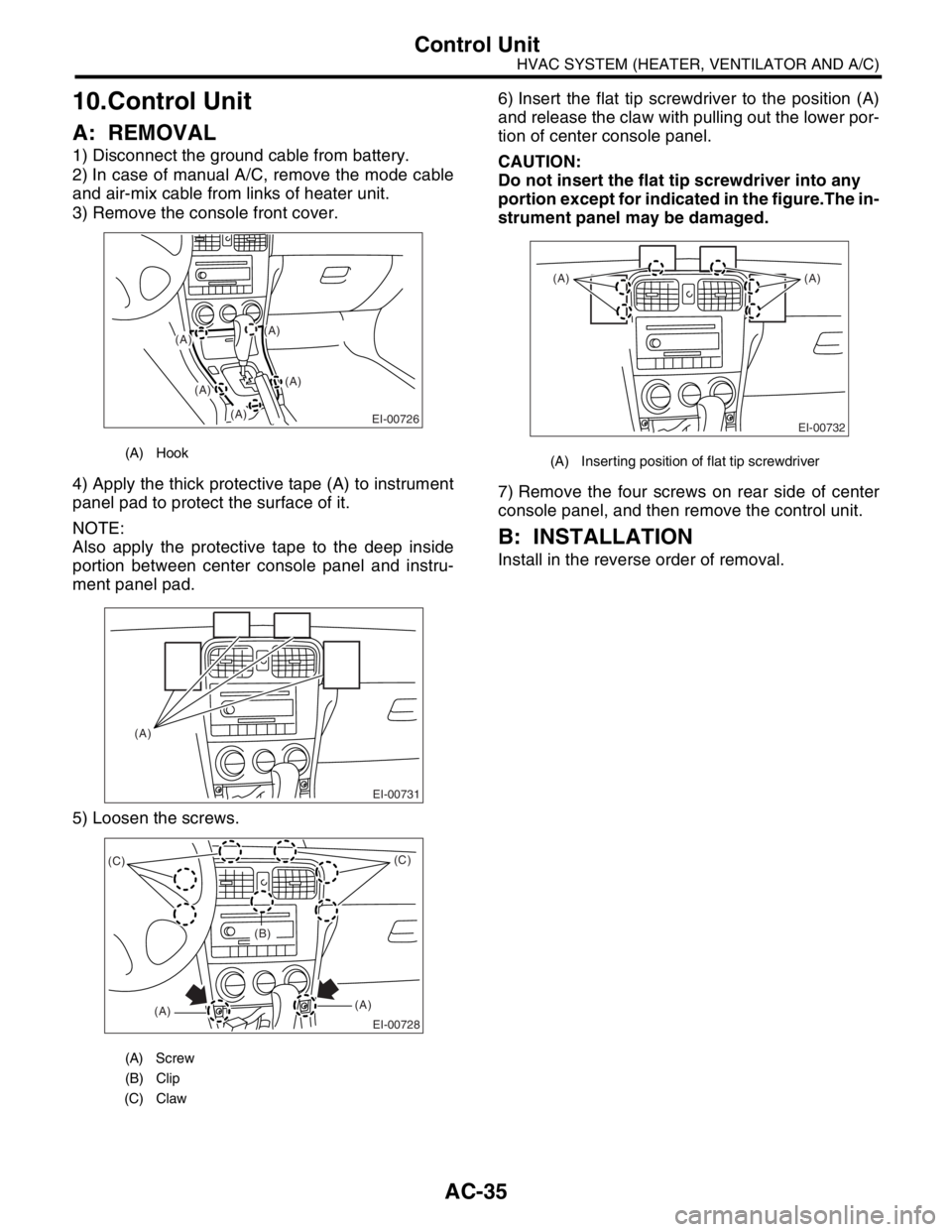
4) Apply the thick protective tape (A) to instrument
panel pad to protect the surface of it.
NOTE:
Also apply the protective tape to the deep inside
portion between center console panel and instru-
ment panel pad.
5) Loosen the screws.6) Insert the flat tip screwdriver to the position (A)
and release the claw with pulling out the lower por-
tion of center console panel.
CAUTION:
Do not insert the flat tip screwdriver into any
portion except for indicated in the figure.The in-
strument panel may be damaged.
7) Remove the four screws on rear side of center
console panel, and then remove the control unit.
B: INSTALLATION
Install in the reverse order of removal.
(A) Hook
(A) Screw
(B) Clip
(C) Claw
(A)
(A)
EI-00726
(A)
(A)
(A)
EI-00731
(A)
EI-00728
(C)
(A)(A)(C)
(B)
(A) Inserting position of flat tip screwdriver
EI-00732
(A) (A)
Page 65 of 2870
AC-9
HVAC SYSTEM (AUTO A/C)(DIAGNOSTIC)
Diagnostic Chart for Self-Diagnosis
5. Diagnostic Chart for Self-Diagnosis
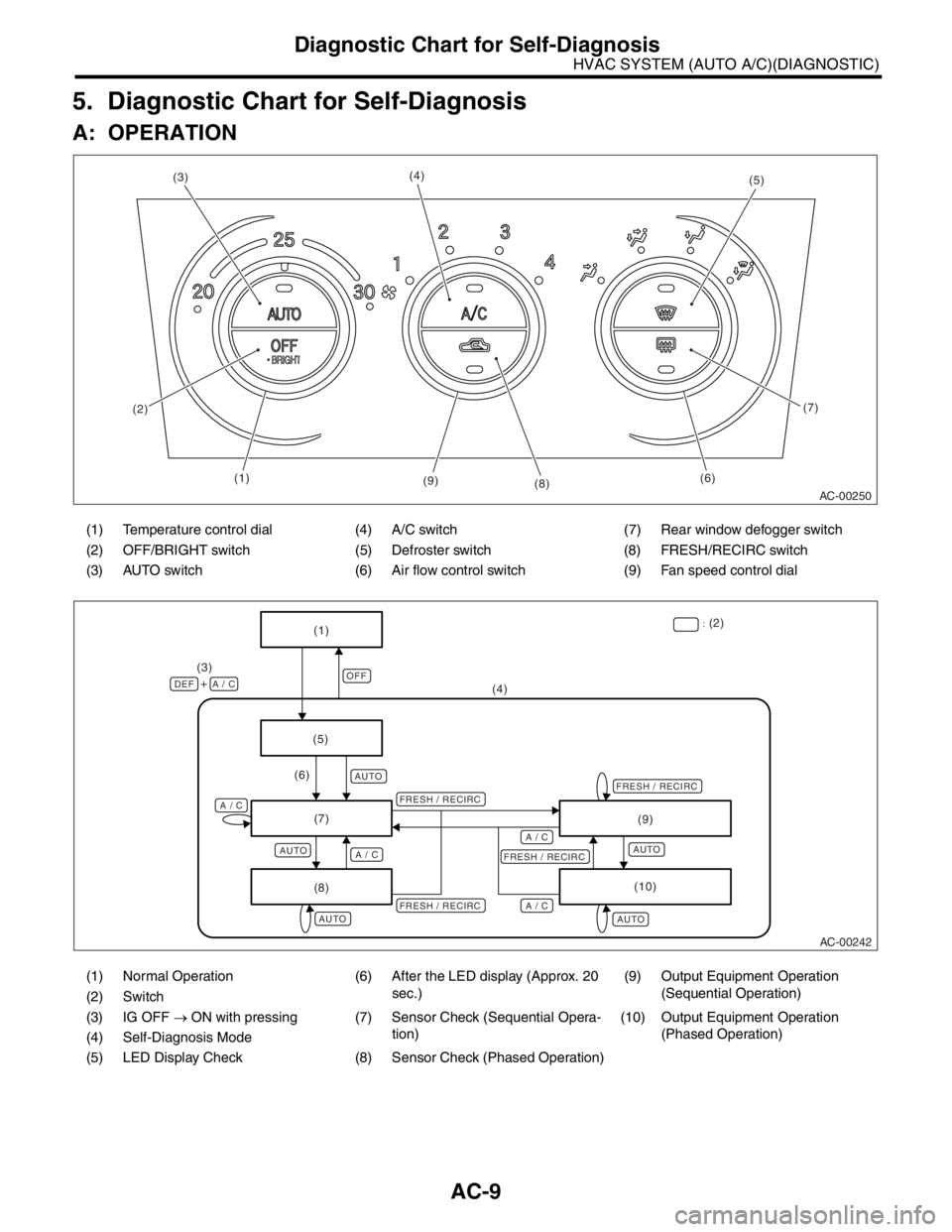
A: OPERATION
(1) Temperature control dial (4) A/C switch (7) Rear window defogger switch
(2) OFF/BRIGHT switch (5) Defroster switch (8) FRESH/RECIRC switch
(3) AUTO switch (6) Air flow control switch (9) Fan speed control dial
(1) Normal Operation (6) After the LED display (Approx. 20
sec.)(9) Output Equipment Operation
(Sequential Operation)
(2) Switch
(3) IG OFF → ON with pressing (7) Sensor Check (Sequential Opera-
tion)(10) Output Equipment Operation
(Phased Operation)
(4) Self-Diagnosis Mode
(5) LED Display Check (8) Sensor Check (Phased Operation)
AC-00250
(5)
(6)(7)
(8) (9) (4)
(3)
(2)
(1)
AC-00242
OFF
AUTO
AUTO
AUTO
AUTOAUTO
(5)(4) (3)
DEF A / C+
A / CA / C
A / C A / C
(6)
(7)
(8)(9)
(10)
FRESH / RECIRCFRESH / RECIRCFRESH / RECIRC
FRESH / RECIRC:
(2)
(1)
Page 66 of 2870

AC-10
HVAC SYSTEM (AUTO A/C)(DIAGNOSTIC)
Diagnostic Chart for Self-Diagnosis
Step Check Yes No
1 SELECT CONTROL PANEL TO SELF-DIAG-
NOSIS MODE.
1) Turn the ignition switch to OFF.
2) Start the engine while pressing defroster
switch and A/C switch.
N
OTE:
Self-diagnosis can also be performed with the
ignition switch ON, but start the engine be-
cause telling the magnet clutch operation is dif-
ficult.
3) The LED in A/C control panel blinks.Does the self-diagnosis mode
operate?Go to step 2.
NOSIS SYS-
TEMS DO NOT
OPERATE, Diag-
nostics for A/C
System Malfunc-
tion.>
2 CHECK LED ILLUMINATION.
Make sure that three LED blink in turn on A/C
control panel (5 patterns are repeated 2 times).Do all LED blink? Go to step 3.Go to step 5.
3 CHECK SENSORS MALFUNCTION.
1) After completing the LED check or when
AUTO switch is pressed, the A/C switch LED
illuminates, and then the sensor check is
started.
2) Check the input signal of each sensor in
turn. If there are any trouble for each sensor,
DEF, MODE and fan speed LEDs are blinked.
Also check for each sensor is possible respec-
tively every time AUTO switch is pressed. (At
this time, the AUTO switch LED illuminates.)
3) If there is no trouble, DEF, MODE and fan
speed LEDs are turned off.
N
OTE:
Rear window defogger LED illuminates in case
of stored malfunction but does not illuminate in
case of present malfunction.Does each DEF, MODE and
fan speed LED turn off?Go to step 4.Confirm the com-
bination of illumi-
nating LEDs by
using Sensor
Check Table, and
identify the mal-
functioning sensor
before repairing.
TABLE, OPERA-
TION, Diagnostic
Chart for Self-
Diagnosis.>
4 CHECK OPERATION OF EACH ACTUATOR,
COMPRESSOR AND FAN MOTOR.
1) Press the FRESH/RECIRC switch
(FRESH/RECIRC switch LED illuminates at
this time.).
2) Refer to OPERATING MODE TABLE to
check the operation of each actuator, compres-
sor and fan motor.
Chart for Self-Diagnosis.>
Also check for each step is possible respec-
tively every time AUTO switch pressed. (At this
time, the AUTO switch LED illuminates.)Does each actuator, compres-
sor and fan motor operate
according to operating mode
table?Press the OFF
switch or turn the
ignition switch to
OFF and finish the
self-diagnosis
mode.Refer to each
diagnostics chart
for actuator, com-
pressor and fan
motor, and repair
the malfunctioning
par t as necessary.
C System Mal-
function.>
Procedure for
Actuators.>
5 CHECK POOR CONTACT.
Check the auto A/C control module connector
for poor contact.Is there a poor contact in con-
nector?Replace the auto
A/C control mod-
ule.Repair the con-
nector.
Page 67 of 2870

AC-11
HVAC SYSTEM (AUTO A/C)(DIAGNOSTIC)
Diagnostic Chart for Self-Diagnosis
1. SENSOR CHECK TABLE
NOTE:
When the sunload sensor is checked indoors or in the shade, open circuit might be indicated. Always check
the sunload sensor at a place where sun shines directly on it.
*1: Only present malfunction is indicated for open circuit of sunload sensor. (However, stored malfunction can be indicated for
short circuit of sunload sensor.)
2. OPERATING MODE TABLE
Diag-
nostic
stepsChecked sensorOpen circuit Short circuitPresent
malfunctionStored
malfunction
DEF LEDMODE/FAN
LEDDEF LEDMODE/FAN
LEDREAR WINDOW
DEFOGGER LED
1 In-vehicle sensor
Tu r n o f fVENT
LED blinks
IlluminateVENT
LED blinks
Turn off Illuminate 2 Ambient sensorBI-LEVEL
LED blinksBI-LEVEL
LED blinks
3 Evaporator sensorHEAT
LED blinksHEAT
LED blinks
4 Sunload sensor*1DEF/HEAT
LED blinksDEF/HEAT
LED blinks
5 Air mix door actuator P.B.R.Fan speed
1st
LED blinksFan speed
1st
LED blinks
6Combination meter commu-
nication (Ambient sensor)Fan speed
2nd
LED blinksFan speed
2nd
LED blinks
When all parts are in good condition Turn off
Step 12345678
Illuminating LEDVENT
LEDBI-LEVEL
VENTHEAT LEDDEF/HEAT
LEDFan speed
1st LEDFan speed
2nd LEDFan speed
3rd LEDFan speed
4th LED
Fan speed LO LO ML ML ML MH MH HI
Mode actuator VENT VENT VENT BI-LEVEL HEAT HEAT DEF/HEAT DEF
Intake actuator FRESH RECIRC RECIRC FRESH FRESH FRESH FRESH FRESH
Air mix door actuatorFULL
COOL
(0%)FULL
COOL
(0%)FULL
COOL
(0%)MEDIUM
(50%)MEDIUM
(50%)FULL HOT
(100%)FULL HOT
(100%)FULL HOT
(100%)
Compressor
(magnet clutch)OFFONONONONONONON
Page 102 of 2870
AB-2
AIRBAG SYSTEM
General Description
1. General Description
A: COMPONENT
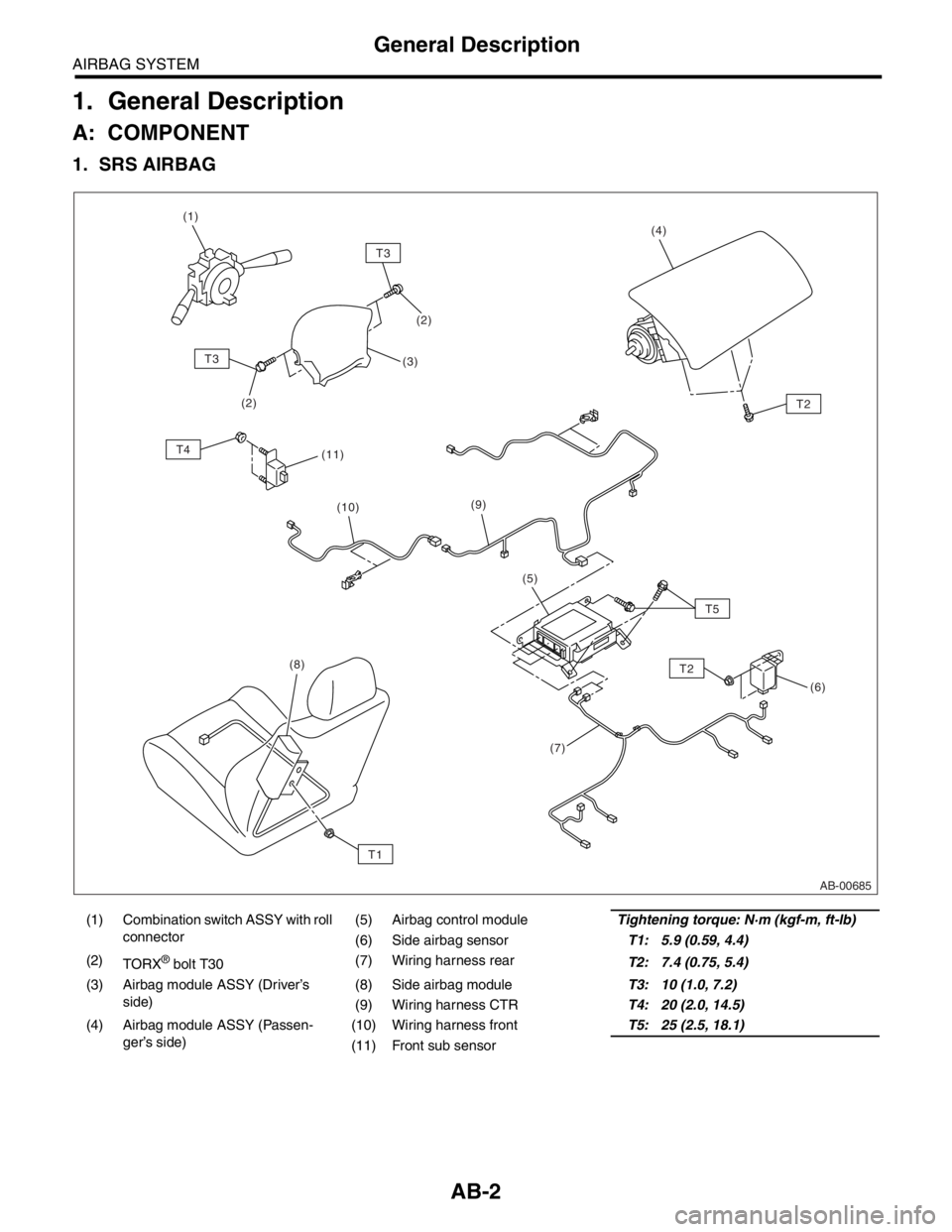
1. SRS AIRBAG
(1) Combination switch ASSY with roll
connector(5) Airbag control moduleTightening torque: N·m (kgf-m, ft-lb)
(6) Side airbag sensorT1: 5.9 (0.59, 4.4)
(2)
TORX
® bolt T30(7) Wiring harness rear
T2: 7.4 (0.75, 5.4)
(3) Airbag module ASSY (Driver’s
side)(8) Side airbag moduleT3: 10 (1.0, 7.2)
(9) Wiring harness CTRT4: 20 (2.0, 14.5)
(4) Airbag module ASSY (Passen-
ger’s side)(10) Wiring harness frontT5: 25 (2.5, 18.1)
(11) Front sub sensor
AB-00685
T3
T2
T5
T3
T4(2)(4)
(3) (1)
(2)
(10)
(11)
(9)
(7)(6) (5)
(8)T2
T1
Page 105 of 2870
AB-5
AIRBAG SYSTEM
General Description
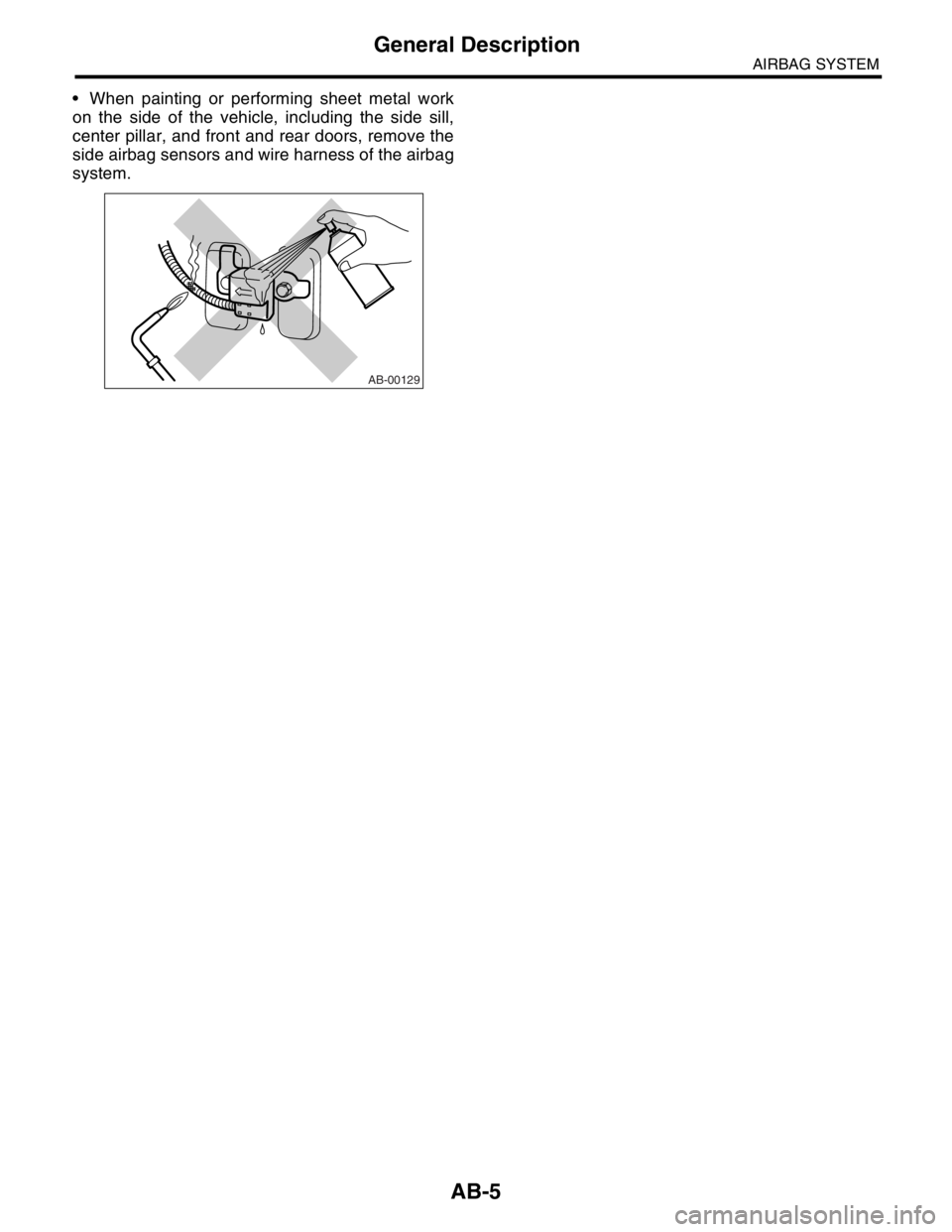
When painting or performing sheet metal work
on the side of the vehicle, including the side sill,
center pillar, and front and rear doors, remove the
side airbag sensors and wire harness of the airbag
system.
AB-00129