water pump SUBARU FORESTER 2004 Service Repair Manual
[x] Cancel search | Manufacturer: SUBARU, Model Year: 2004, Model line: FORESTER, Model: SUBARU FORESTER 2004Pages: 2870, PDF Size: 38.67 MB
Page 721 of 2870

RM-6
RECOMMENDED MATERIAL
Recommended Materials
8. ADHESIVES
Use the adhesives shown in the table below, or equivalent.
Grease MT main shaft FX 2200 clutch grease 000040901 —
Clutch master cylinder
push rodSlicolube G-40M 004404003 —
Gear shift lever
Select lever
Clutch operating cyl-
inder
Accelerator pedal
Clutch pedal
Brake pedal
Hill holder
Clutch bearing
Clutch release lever
Steering shaft bear-
ingSUNLIGHT2 003602010 —
Steering gearbox Valiant grease M-2 003608001 —
Disc brake Niglube RX-2 K0779GA102 —
Drum brake
Drum brake wheel
cylinderMolykote No. 7439 003602001 —
Brake pad
Brake shoeMolykote AS-880N K0777YA010 —
Front axle AARi One luber C — —
Front axle AC HTBJ — —
Rear axle BJ Molylex No. 2 003601001 —
Rear axle EBJ NTG2218 — —
Rear axle DOJ VU-3A702 23223GA050 —
Water pump
Door latch
Door strikerSlicolube G-30M 004404002 —
Adhesive Application point Recommended Item number Alternative
Adhesive Windshield and body Dow Automotive’s
Adhesive: Gurit-ESSEX
Betaseal 1502 or equivalent
Glass primer: Betawipe VP
04604 or Betawipe 5001
Paint surface primer: Betap-
rime 5402——
Soft vinyl Cemedine 540 — 3M’s EC-776 EC-847 or EC-1022
(Spray type)
Momentary sealant Cemedine 3000 — Armstrong’s Eastman 910
Inner rearview mirror
baseREPAIR KIT IN MR 65029FC000 — Grease Application point Recommended Item number Alternative
Page 748 of 2870
PM-11
PERIODIC MAINTENANCE SERVICE
V-belt
6. V-belt
A: INSPECTION
1) Replace the belts, if cracks, fraying or wear is
found.
2) Check the V-belt tension and adjust it if neces-
sary by changing the generator installing position
or idler pulley installing position.
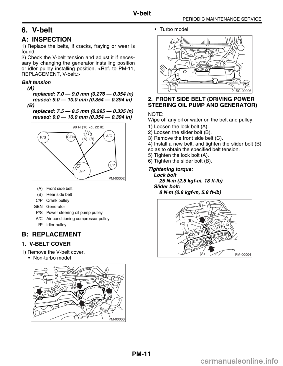
Belt tension
(A)
replaced: 7.0 — 9.0 mm (0.276 — 0.354 in)
reused: 9.0 — 10.0 mm (0.354 — 0.394 in)
(B)
replaced: 7.5 — 8.5 mm (0.295 — 0.335 in)
reused: 9.0 — 10.0 mm (0.354 — 0.394 in)
B: REPLACEMENT
1. V-BELT COVER
1) Remove the V-belt cover.
Non-turbo model Turbo model
2. FRONT SIDE BELT (DRIVING POWER
STEERING OIL PUMP AND GENERATOR)
NOTE:
Wipe off any oil or water on the belt and pulley.
1) Loosen the lock bolt (A).
2) Loosen the slider bolt (B).
3) Remove the front side belt (C).
4) Install a new belt, and tighten the slider bolt (B)
so as to obtain the specified belt tension.
5) Tighten the lock bolt (A).
6) Tighten the slider bolt (B).
Tightening torque:
Lock bolt
25 N·m (2.5 kgf-m, 18 ft-lb)
Slider bolt:
8 N·m (0.8 kgf-m, 5.8 ft-lb)
(A) Front side belt
(B) Rear side belt
C/P Crank pulley
GEN Generator
P/S Power steering oil pump pulley
A/C Air conditioning compressor pulley
I/P Idler pulley
C/P P/SA/C
GEN
(A)(B) 98 N (10 kg, 22 lb)
I/P
PM-00002
PM-00003
SC-00096
PM-00004
(B)
(C)
(A)
Page 752 of 2870
PM-15
PERIODIC MAINTENANCE SERVICE
Timing Belt
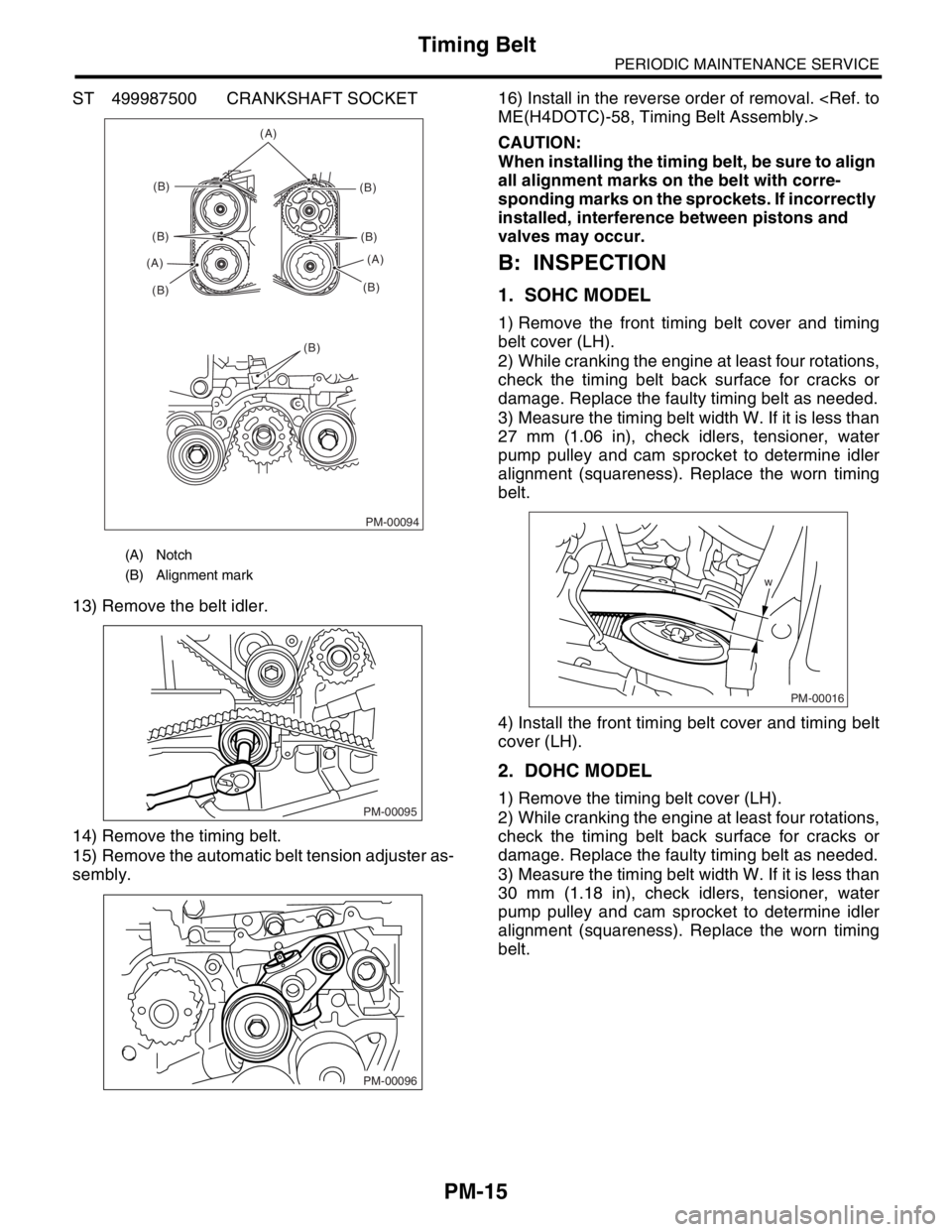
ST 499987500 CRANKSHAFT SOCKET
13) Remove the belt idler.
14) Remove the timing belt.
15) Remove the automatic belt tension adjuster as-
sembly.16) Install in the reverse order of removal.
CAUTION:
When installing the timing belt, be sure to align
all alignment marks on the belt with corre-
sponding marks on the sprockets. If incorrectly
installed, interference between pistons and
valves may occur.
B: INSPECTION
1. SOHC MODEL
1) Remove the front timing belt cover and timing
belt cover (LH).
2) While cranking the engine at least four rotations,
check the timing belt back surface for cracks or
damage. Replace the faulty timing belt as needed.
3) Measure the timing belt width W. If it is less than
27 mm (1.06 in), check idlers, tensioner, water
pump pulley and cam sprocket to determine idler
alignment (squareness). Replace the worn timing
belt.
4) Install the front timing belt cover and timing belt
cover (LH).
2. DOHC MODEL
1) Remove the timing belt cover (LH).
2) While cranking the engine at least four rotations,
check the timing belt back surface for cracks or
damage. Replace the faulty timing belt as needed.
3) Measure the timing belt width W. If it is less than
30 mm (1.18 in), check idlers, tensioner, water
pump pulley and cam sprocket to determine idler
alignment (squareness). Replace the worn timing
belt.
(A) Notch
(B) Alignment mark
PM-00094
(A)
(B)
(B)
(B) (A)(B)
(B)
(B)(A)
(B)
PM-00095
PM-00096
w
PM-00016
Page 757 of 2870
PM-20
PERIODIC MAINTENANCE SERVICE
Cooling System
11.Cooling System
A: INSPECTION
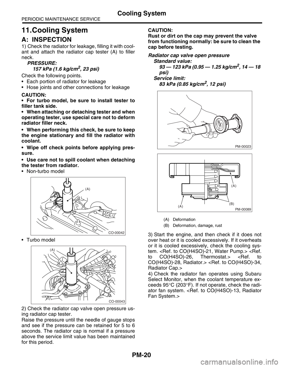
1) Check the radiator for leakage, filling it with cool-
ant and attach the radiator cap tester (A) to filler
neck.
PRESSURE:
157 kPa (1.6 kg/cm
2, 23 psi)
Check the following points.
Each portion of radiator for leakage
Hose joints and other connections for leakage
CAUTION:
For turbo model, be sure to install tester to
filler tank side.
When attaching or detaching tester and when
operating tester, use special care not to deform
radiator filler neck.
When performing this check, be sure to keep
the engine stationary and fill the radiator with
coolant.
Wipe off check points before applying pres-
sure.
Use care not to spill coolant when detaching
the tester from radiator.
Non-turbo model
Turbo model
2) Check the radiator cap valve open pressure us-
ing radiator cap tester.
Raise the pressure until the needle of gauge stops
and see if the pressure can be retained for 5 to 6
seconds. The radiator cap is normal if a pressure
above the service limit value has been maintained
for this period.CAUTION:
Rust or dirt on the cap may prevent the valve
from functioning normally: be sure to clean the
cap before testing.
Radiator cap valve open pressure
Standard value:
93 — 123 kPa (0.95 — 1.25 kg/cm2, 14 — 18
psi)
Service limit:
83 kPa (0.85 kg/cm
2, 12 psi)
3) Start the engine, and then check if it does not
over heat or it is cooled excessively. If it overheats
or it is cooled excessively, check the cooling sys-
tem.
4) Check the radiator fan operates using Subaru
Select Monitor, when the coolant temperature ex-
ceeds 95°C (203°F). If not operate, check the radi-
ator fan system.
CO-00042
(A)
CO-00043
(A)
(A) Deformation
(B) Deformation, damage, rust
PM-00023
PM-00089
(B)
(A)(A)
Page 848 of 2870

FU(H4SO)-66
FUEL INJECTION (FUEL SYSTEM)
Fuel System Trouble in General
29.Fuel System Trouble in General
A: INSPECTION
NOTE:
When the vehicle is left unattended for an ex-
tended period of time, water may accumulate in the
fuel tank.
To prevent water condensation.
(1) Top off the fuel tank or drain the fuel com-
pletely.
(2) Drain the water condensation from the fuel
filter.
Refilling the fuel tank.
Refill the fuel tank while there is still some fuel left in
the tank.
Protecting the fuel system against freezing and
water condensation.
(3) Cold areas :
In snow-covered areas, mountainous areas, ski-
ing areas, etc. where ambient temperatures
drop below 0°C (32°F) throughout the winter
season, use an anti-freeze solution in the fuel
tank. Refueling will also complement the effect
of anti-freeze solution each time the fuel leveldrops to about one-half. After the winter season,
drain the water which may have accumulated in
the fuel filter and fuel tank in the manner same
as that described under “Affected areas” below.
(4) Affected areas :
When the water condensation is notched in the
fuel filter, drain the water from both the fuel filter
and fuel tank or use a water removing agent (or
anti-freeze solution) in the fuel tank.
Observe the instructions, notes, etc., indicated
on the label affixed to the anti-freeze solution (wa-
ter removing agent) container before use.
Trouble and possible cause Corrective action
1. Insufficient fuel supply to the injector
1) Fuel pump will not operate.
❍Defective terminal contact.Inspect connections, especially ground, and tighten
securely.
❍Trouble in electromagnetic or electronic circuit parts. Replace fuel pump.
2) Lowering of fuel pump function. Replace fuel pump.
3) Clogged dust or water in the fuel filter. Replace fuel filter, clean or replace fuel tank.
4) Clogged or bent fuel pipe or hose. Clean, correct or replace fuel pipe or hose.
5) Air is mixed in the fuel system. Inspect or retighten each connection part.
6) Clogged or bent breather tube or pipe. Clean, correct or replace air breather tube or pipe.
7) Damaged diaphragm of pressure regulator. Replace.
2. Leakage or blow out fuel
1) Loosened joints of the fuel pipe. Retightening.
2) Cracked fuel pipe, hose and fuel tank. Replace.
3) Defective welding part on the fuel tank. Replace.
4) Defective drain packing of the fuel tank. Replace.
5) Clogged or bent air breather tube or air vent tube.Clean, correct or replace air breather tube or air vent
tube.
3. Gasoline smell inside of compartment
1)Loose joints at air breather tube, air vent tube and fuel filler
pipe.Retightening.
2) Defective packing air tightness on the fuel saucer. Correct or replace packing.
3) Cracked fuel separator. Replace separator.
4) Inoperative fuel pump modulator or circuit. Replace.
4. Defective fuel meter indicator
1) Defective operation of fuel level sensor. Replace.
2) Defective operation of fuel meter. Replace.
5. Noise
1) Large operation noise or vibration of fuel pump. Replace.
Page 879 of 2870
ME(H4SO)-10
MECHANICAL
General Description
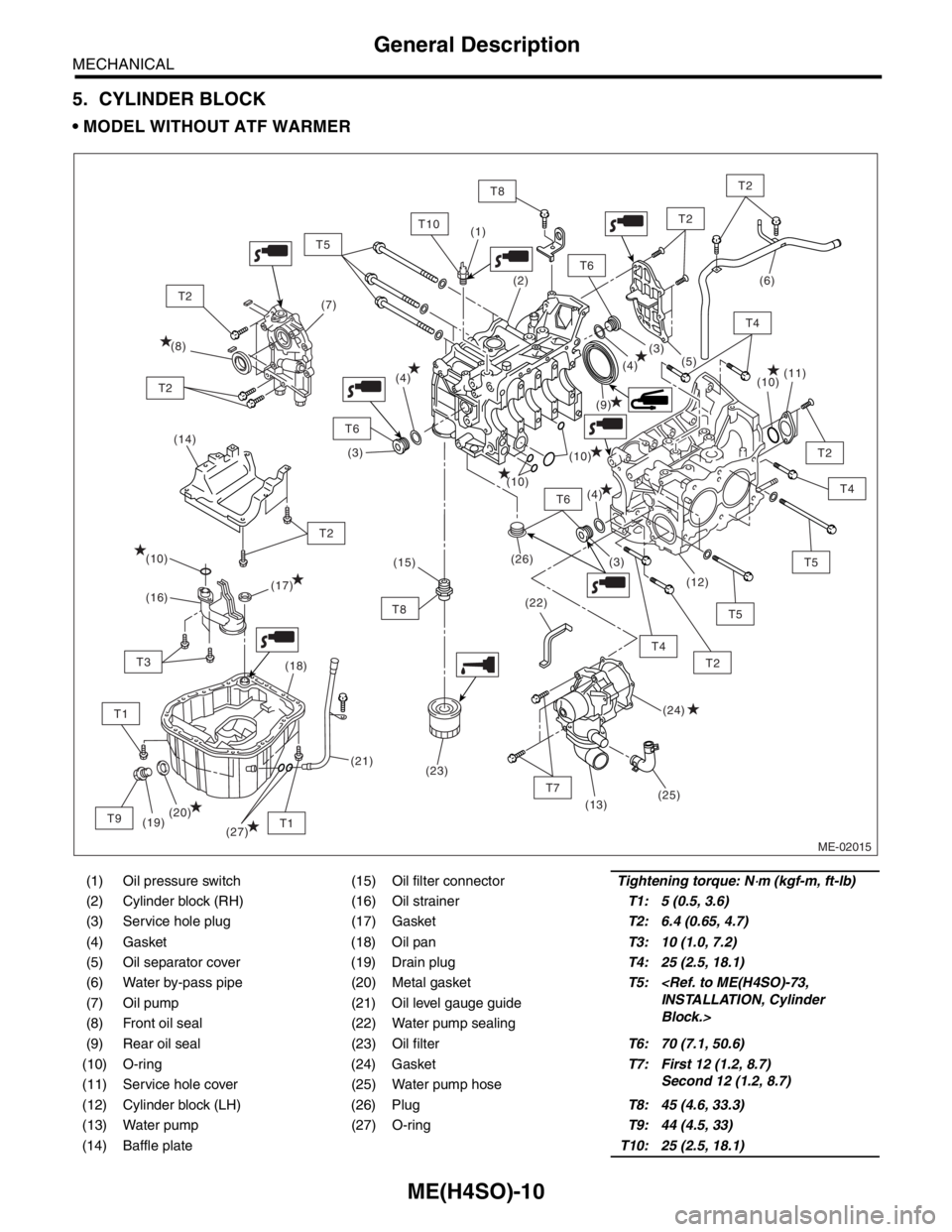
5. CYLINDER BLOCK
MODEL WITHOUT ATF WARMER
(1) Oil pressure switch (15) Oil filter connectorTightening torque: N⋅m (kgf-m, ft-lb)
(2) Cylinder block (RH) (16) Oil strainerT1: 5 (0.5, 3.6)
(3) Service hole plug (17) GasketT2: 6.4 (0.65, 4.7)
(4) Gasket (18) Oil panT3: 10 (1.0, 7.2)
(5) Oil separator cover (19) Drain plugT4: 25 (2.5, 18.1)
(6) Water by-pass pipe (20) Metal gasketT5:
Block.> (7) Oil pump (21) Oil level gauge guide
(8) Front oil seal (22) Water pump sealing
(9) Rear oil seal (23) Oil filterT6: 70 (7.1, 50.6)
(10) O-ring (24) GasketT7: First 12 (1.2, 8.7)
Second 12 (1.2, 8.7)
(11) Service hole cover (25) Water pump hose
(12) Cylinder block (LH) (26) PlugT8: 45 (4.6, 33.3)
(13) Water pump (27) O-ringT9: 44 (4.5, 33)
(14) Baffle plateT10: 25 (2.5, 18.1)
ME-02015
(14)
T6
T7
T2
T2
T4
T8
T4
T5
T2
T6
T6
T10
T1
T2
T8
T1
T3
T9
T2
T2
(9) (8)(7)(6)
(10)
(10)
(10)
(26)
(22)(11)
(12)
(13)
(19)(18)
(20)(17)
(16)
(24) (10)
(25)(5)
(4)
(4)
(4)(3)
(3)
(3) (2) (1)
(21)(15)
(23)
T5
T2
T5
T4
(27)
Page 880 of 2870
ME(H4SO)-11
MECHANICAL
General Description
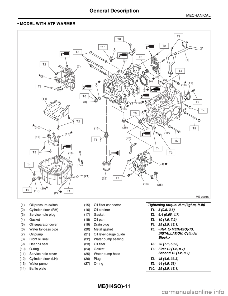
MODEL WITH ATF WARMER
(1) Oil pressure switch (15) Oil filter connectorTightening torque: N⋅m (kgf-m, ft-lb)
(2) Cylinder block (RH) (16) Oil strainerT1: 5 (0.5, 3.6)
(3) Service hole plug (17) GasketT2: 6.4 (0.65, 4.7)
(4) Gasket (18) Oil panT3: 10 (1.0, 7.2)
(5) Oil separator cover (19) Drain plugT4: 25 (2.5, 18.1)
(6) Water by-pass pipe (20) Metal gasketT5:
Block.> (7) Oil pump (21) Oil level gauge guide
(8) Front oil seal (22) Water pump sealing
(9) Rear oil seal (23) Oil filterT6: 70 (7.1, 50.6)
(10) O-ring (24) GasketT7: First 12 (1.2, 8.7)
Second 12 (1.2, 8.7)
(11) Service hole cover (25) Water pump hose
(12) Cylinder block (LH) (26) PlugT8: 45 (4.6, 33.3)
(13) Water pump (27) O-ringT9: 44 (4.5, 33)
(14) Baffle plateT10: 25 (2.5, 18.1)
ME-02016
(14)
T6
T2
T2
T4
T8
T5
T2
T6
T6
T10
T1
T2
T8
T1
T3
T9
T2
T2
(9) (8)(7)
(10)
(10)
(10)
(26)
(22)(11)
(12)
(19)(18)
(20)(17)
(16)
(24) (10)
(25)(5)
(4)
(4)
(4)(3)
(3)
(3) (2) (1)
(21)(15)
(23)
T5
T2
T5
T4
(27)
T7
(13)
(6)
T4
Page 941 of 2870
ME(H4SO)-70
MECHANICAL
Cylinder Block
NOTE:
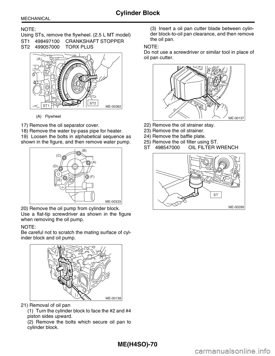
Using STs, remove the flywheel. (2.5 L MT model)
ST1 498497100 CRANKSHAFT STOPPER
ST2 499057000 TORX PLUS
17) Remove the oil separator cover.
18) Remove the water by-pass pipe for heater.
19) Loosen the bolts in alphabetical sequence as
shown in the figure, and then remove water pump.
20) Remove the oil pump from cylinder block.
Use a flat-tip screwdriver as shown in the figure
when removing the oil pump.
NOTE:
Be careful not to scratch the mating surface of cyl-
inder block and oil pump.
21) Removal of oil pan
(1) Turn the cylinder block to face the #2 and #4
piston sides upward.
(2) Remove the bolts which secure oil pan to
cylinder block.(3) Insert a oil pan cutter blade between cylin-
der block-to-oil pan clearance, and then remove
the oil pan.
NOTE:
Do not use a screwdriver or similar tool in place of
oil pan cutter.
22) Remove the oil strainer stay.
23) Remove the oil strainer.
24) Remove the baffle plate.
25) Remove the oil filter using ST.
ST 498547000 OIL FILTER WRENCH
(A) Flywheel
(A)
ME-00382
ST1ST2
ME-00333
(B)
(F) (D)(C)
(A)
(E)
ME-00138
ME-00137
ME-00299
ST
Page 951 of 2870
ME(H4SO)-80
MECHANICAL
Cylinder Block
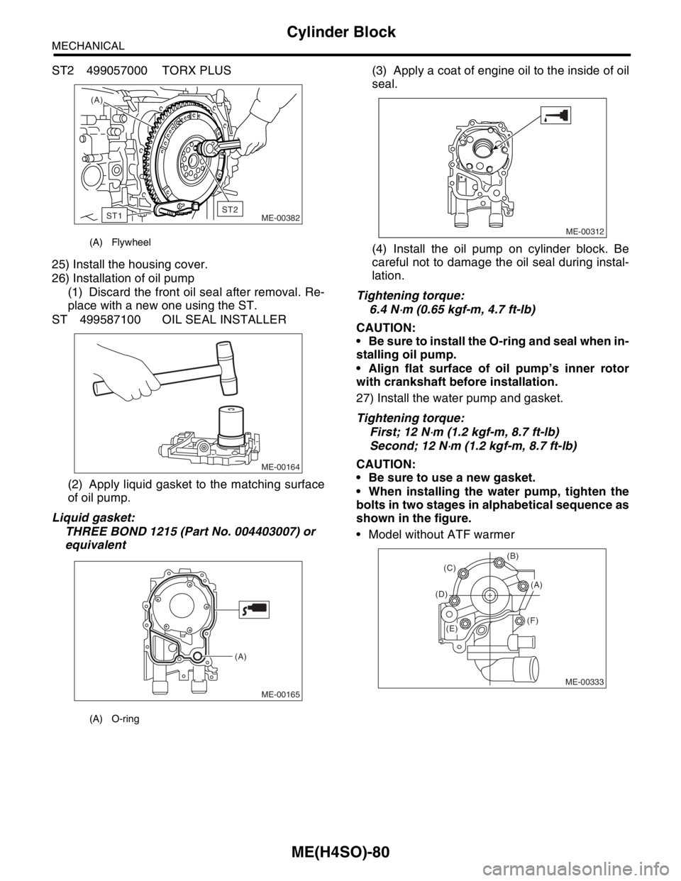
ST2 499057000 TORX PLUS
25) Install the housing cover.
26) Installation of oil pump
(1) Discard the front oil seal after removal. Re-
place with a new one using the ST.
ST 499587100 OIL SEAL INSTALLER
(2) Apply liquid gasket to the matching surface
of oil pump.
Liquid gasket:
THREE BOND 1215 (Part No. 004403007) or
equivalent(3) Apply a coat of engine oil to the inside of oil
seal.
(4) Install the oil pump on cylinder block. Be
careful not to damage the oil seal during instal-
lation.
Tightening torque:
6.4 N
⋅m (0.65 kgf-m, 4.7 ft-lb)
CAUTION:
Be sure to install the O-ring and seal when in-
stalling oil pump.
Align flat surface of oil pump’s inner rotor
with crankshaft before installation.
27) Install the water pump and gasket.
Tightening torque:
First; 12 N
⋅m (1.2 kgf-m, 8.7 ft-lb)
Second; 12 N
⋅m (1.2 kgf-m, 8.7 ft-lb)
CAUTION:
Be sure to use a new gasket.
When installing the water pump, tighten the
bolts in two stages in alphabetical sequence as
shown in the figure.
Model without ATF warmer
(A) Flywheel
(A) O-ring
(A)
ME-00382
ST1ST2
ME-00164
ME-00165
(A)
ME-00312
ME-00333
(B)
(F) (D)(C)
(A)
(E)
Page 967 of 2870

ME(H4SO)-96
MECHANICAL
Engine Noise
23.Engine Noise
A: INSPECTION
NOTE*:
When disconnecting fuel injector connector, the malfunction indicator light illuminates and DTC is stored in ECM memory.
Therefore, carry out the clear memory mode
Regular clicking soundSound increases as engine
speed increases. Valve mechanism is defective.
Incorrect valve clearance
Worn valve rocker
Worn camshaft
Broken valve spring
Heavy and dull clankOil pressure is low. Worn crankshaft main bearing
Worn connecting rod bearing (big end)
Oil pressure is normal. Loose flywheel mounting bolts
Damaged engine mounting
High-pitched clank (Spark
knock)Sound is noticeable when
accelerating with an overload. Ignition timing advanced
Accumulation of carbon inside combustion chamber
Wrong spark plug
Improper gasoline
Clank when engine speed is
medium (1,000 to 2,000 rpm).Sound is reduced when fuel
injector connector of noisy cyl-
inder is disconnected.
(NOTE*) Worn crankshaft main bearing
Worn bearing at crankshaft end of connecting rod
Knocking sound when engine
is operating under idling speed
and engine is warmSound is reduced when fuel
injector connector of noisy cyl-
inder is disconnected.
(NOTE*) Worn cylinder liner and piston ring
Broken or stuck piston ring
Worn piston pin and hole at piston end of connecting rod
Sound is not reduced if each
fuel injector connector is dis-
connected in turn. (NOTE*) Unusually worn valve lifter
Worn cam gear
Worn camshaft journal bore in crankcase
Squeaky sound — Insufficient generator lubrication
Rubbing sound — Defective generator brush and rotor contact
Gear scream when starting
engine— Defective ignition starter switch
Worn gear and starter pinion
Sound like polishing glass with
a dry cloth— Loose drive belt
Defective water pump shaft
Hissing sound — Loss of compression
Air leakage in air intake system, hoses, connections or mani-
folds
Timing belt noise — Loose timing belt
Belt contacting case/adjacent part
Valve tappet noise — Incorrect valve clearance