cooling SUBARU FORESTER 2010 SH / 3.G Owners Manual
[x] Cancel search | Manufacturer: SUBARU, Model Year: 2010, Model line: FORESTER, Model: SUBARU FORESTER 2010 SH / 3.GPages: 402, PDF Size: 14.36 MB
Page 156 of 402
Ventilator.............................................................. 4-2
Airflow selection ................................................. 4-2
Center and side ventilators .................................. 4-3
Manual climate control system (if equipped) ..................................................... 4-3
Control panel ...................................................... 4-3
Heater operation ................................................. 4-5
Air conditioner operation ..................................... 4-7
Automatic climate control system (if equipped) ..................................................... 4-8
Control panel ...................................................... 4-8
To use as full-automatic climate control system .............................................................. 4-8
To use as semi-automatic climate control system .............................................................. 4-8
Fan speed control dial ......................................... 4-9
Temperature control dial ...................................... 4-9
Airflow control dial .............................................. 4-9
Air inlet selection button .................................... 4-10 Air conditioner button
........................................ 4-10
Temperature sensors ......................................... 4-11
Operating tips for heater and air conditioner ...................................................... 4-12
Cleaning ventilation grille ................................... 4-12
Efficient cooling after parking in direct sunlight ........................................................... 4-12
Lubrication oil circulation in the refrigerant circuit ............................................................. 4-12
Checking air conditioning system before summer season ............................................... 4-12
Cooling and dehumidifying in high humidity and low temperature weather conditions ................. 4-12
Air conditioner compressor shut-off when engine is heavily loaded .............................................. 4-12
Refrigerant for your climate control system ... ..... 4-12
Air filtration system ........................................... 4-13
Replacing an air filter ......................................... 4-13Climate control
4
Page 159 of 402
4-4Climate control
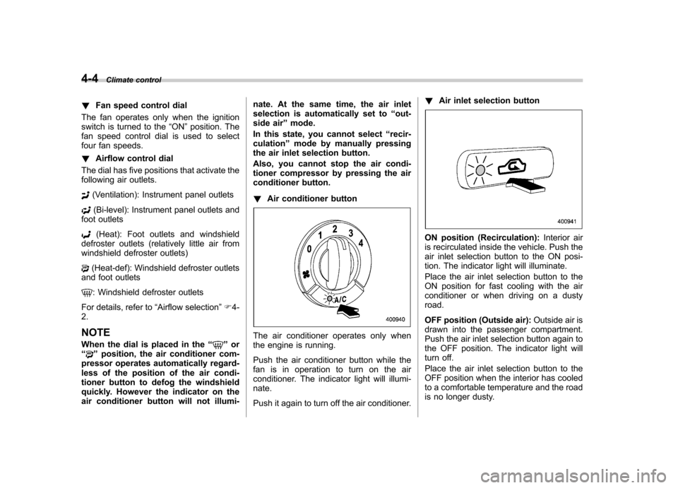
! Fan speed control dial
The fan operates only when the ignition
switch is turned to the “ON ”position. The
fan speed control dial is used to select
four fan speeds. ! Airflow control dial
The dial has five positions that activate the
following air outlets.
(Ventilation): Instrument panel outlets
(Bi-level): Instrument panel outlets and
foot outlets
(Heat): Foot outlets and windshield
defroster outlets (relatively little air from
windshield defroster outlets)
(Heat-def): Windshield defroster outlets
and foot outlets
: Windshield defroster outlets
For details, refer to “Airflow selection ”F 4-
2. NOTE
When the dial is placed in the “
”or
“” position, the air conditioner com-
pressor operates automatically regard-
less of the position of the air condi-
tioner button to defog the windshield
quickly. However the indicator on the
air conditioner button will not illumi- nate. At the same time, the air inlet
selection is automatically set to
“out-
side air ”mode.
In this state, you cannot select “recir-
culation ”mode by manually pressing
the air inlet selection button.
Also, you cannot stop the air condi-
tioner compressor by pressing the air
conditioner button. ! Air conditioner button
The air conditioner operates only when
the engine is running.
Push the air conditioner button while the
fan is in operation to turn on the air
conditioner. The indicator light will illumi-nate.
Push it again to turn off the air conditioner. !
Air inlet selection button
ON position (Recirculation): Interior air
is recirculated inside the vehicle. Push the
air inlet selection button to the ON posi-
tion. The indicator light will illuminate.
Place the air inlet selection button to the
ON position for fast cooling with the air
conditioner or when driving on a dustyroad.
OFF position (Outside air): Outside air is
drawn into the passenger compartment.
Push the air inlet selection button again to
the OFF position. The indicator light will
turn off.
Place the air inlet selection button to the
OFF position when the interior has cooled
to a comfortable temperature and the road
is no longer dusty.
Page 162 of 402
When driving on a dusty road, set the air
inlet selection button to the“ON ”position.
WARNING
Continued operation with the air
inletselectionbuttonintheON
position may fog up the windows.
Switch to the OFF position as soon
as the outside dusty conditionclears.
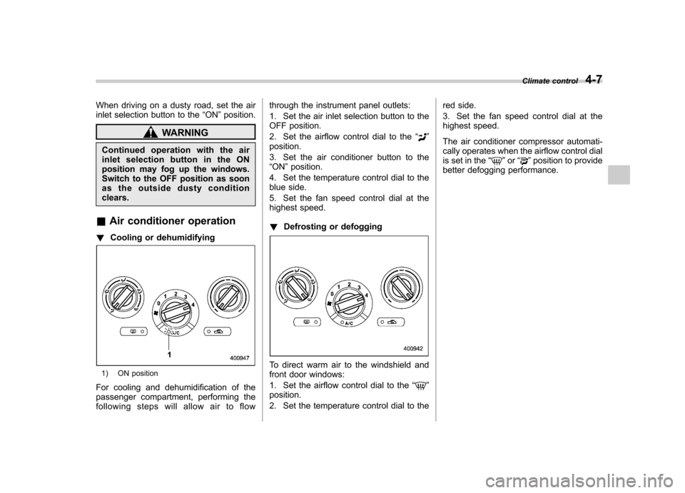
& Air conditioner operation
! Cooling or dehumidifying
1) ON position
For cooling and dehumidification of the
passenger compartment, performing the
following steps will allow air to flow through the instrument panel outlets:
1. Set the air inlet selection button to the
OFF position.
2. Set the airflow control dial to the
“
”
position.
3. Set the air conditioner button to the “ ON ”position.
4. Set the temperature control dial to the
blue side.
5. Set the fan speed control dial at the
highest speed. ! Defrosting or defogging
To direct warm air to the windshield and
front door windows:
1. Set the airflow control dial to the “
”
position.
2. Set the temperature control dial to the red side.
3. Set the fan speed control dial at the
highest speed.
The air conditioner compressor automati-
cally operates when the airflow control dial
is set in the
“
”or “”position to provide
better defogging performance. Climate control
4-7
Page 163 of 402

4-8Climate control
Automatic climate control
system (if equipped)
Although this climate control system can
be used as a full-automatic climate control
system, it can also, if desired, be used as
a semi-automatic climate control system.
When it is used as a full-automatic climate
control system, the outlet air temperature,
fan speed, airflow distribution, air inlet
control, and air conditioner compressor
operation are all automatically controlled
to maintain a constant, comfortable tem-
perature inside the vehicle. NOTE .Operate the automatic climate con-
trol system when the engine is running. . When the engine coolant is cold, the
blower does not run.. In the “AUTO ”mode, when the air
temperature in the passenger compart-
ment is sufficiently cool, the air condi-
tioner compressor does not operate.
For efficient defogging or dehumidify-
ing in cold weather, press the “A/C ”
button to operate the air conditioner
compressor.. Even when cooling is not necessary,
setting the temperature much lower
than the current outlet air temperature
turns on the air conditioner compres- sor automatically and the
“A/C ”indi-
cator light on the control panel illumi-nates. & Control panel
1) Temperature control dial
2) Fan speed control dial
3) Airflow control dial
4) Control switch of the defogger and deicer
system (Refer to “Defogger and deicer ”
F 3-40.)
5) Air inlet selection button
6) Air conditioner button
& To use as full-automatic cli-
mate control system
Place the temperature control dial in the
position for your desired temperature, then set the other dials and buttons as de-
scribed in the following. The system
’s
functions will then switch to AUTO mode
and be controlled automatically. . Airflow control dial: AUTO position
. Fan speed control dial: AUTO position
& To use as semi-automatic
climate control system
Each function can be individually set to
AUTO mode independently of the others.
Any function set to AUTO mode is con-
trolled automatically. Any function not set
to AUTO mode can be manually adjusted
as desired.
The temperature can be set within a range
of 65 to 85 8F (20 to 30 8C).
Page 164 of 402

&Fan speed control dial
The fan operates only with the ignition
switch in the ON position. The fan speed
control dial is used to select the AUTO
(automatic control) mode or to select the
desired fan speed. The dial ’s positions
and their functions are as follows. OFF: The fan does not operate.
AUTO: The fan speed is adjusted auto-
maticallyinaccordancewiththeair
temperature inside and outside the pas-
senger compartment, the intensity of sun-
light, and other factors. SUBARU recom-
mends using the AUTO position.
Other positions: The fan speed can be
adjusted in 7 steps. NOTE
With the fan speed control dial in the
AUTO position and the airflow control
dial in the
“
”, “”,or “”position,
the fan does not operate during engine
warm-up until the engine coolant tem-
perature exceeds approximately 122 8F
(50 8C).
& Temperature control dial
This dial is used to set the desired interior
temperature. With the dial set to your
desired temperature, the system automa-
tically adjusts the temperature of air
supplied from the outlets such that the
desired temperature is achieved andmaintained.
If the dial is turned fully counterclockwise, the system gives maximum cooling per-
formance. If the dial is turned fully clock-
wise, the system gives maximum heatingperformance. &
Airflow control dial
The dial has six positions that activate the
following outlets. AUTO: The airflow control is adjusted
automatically in accordance with the air
temperature inside and outside the pas-
senger compartment, the intensity of sun-
light, and other factors. SUBARU recom-
mends using the AUTO position.
(Ventilation): Instrument panel outlets
(Bi-level): Instrument panel outlets and
foot outlets Climate control
4-9
– CONTINUED –
Page 165 of 402
4-10Climate control
(Heat): Foot outlets and windshield
defroster outlets (relatively little air from
windshield defroster outlets)
(Heat-def): Windshield defroster outlets
and foot outlets
: Windshield defroster outlets
For details, refer to “Airflow selection ”F 4-
2. NOTE
When the dial is placed in the “
”or
“” position, the air inlet selection is
automatically set to “outside air ”
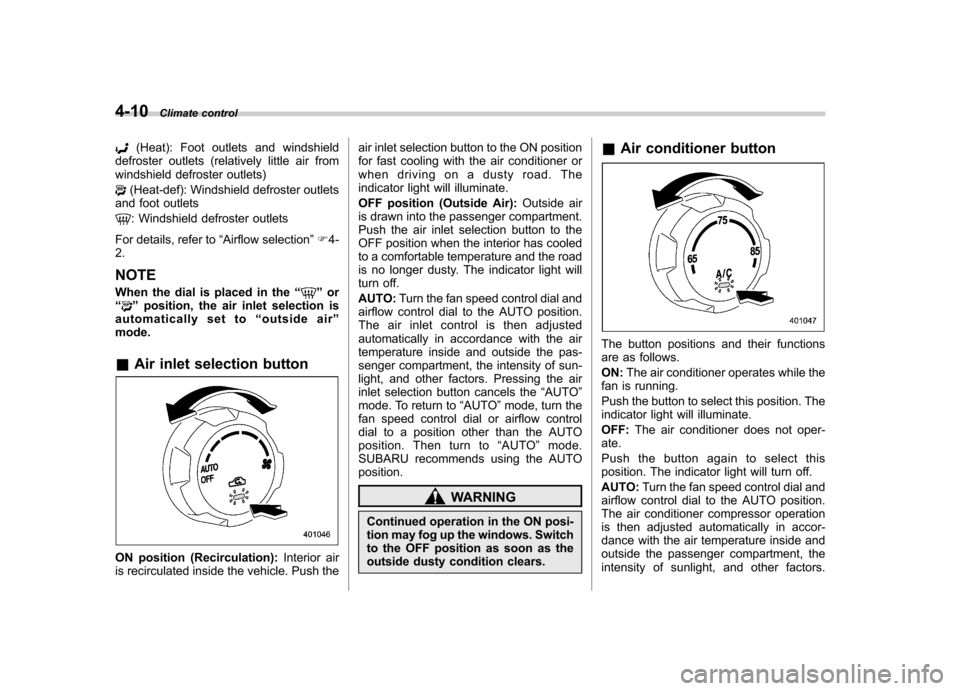
mode. & Air inlet selection button
ON position (Recirculation): Interior air
is recirculated inside the vehicle. Push the air inlet selection button to the ON position
for fast cooling with the air conditioner or
when driving on a dusty road. The
indicator light will illuminate.
OFF position (Outside Air):
Outside air
is drawn into the passenger compartment.
Push the air inlet selection button to the
OFF position when the interior has cooled
to a comfortable temperature and the road
is no longer dusty. The indicator light will
turn off. AUTO: Turn the fan speed control dial and
airflow control dial to the AUTO position.
The air inlet control is then adjusted
automatically in accordance with the air
temperature inside and outside the pas-
senger compartment, the intensity of sun-
light, and other factors. Pressing the air
inlet selection button cancels the “AUTO ”
mode. To return to “AUTO ”mode, turn the
fan speed control dial or airflow control
dial to a position other than the AUTO
position. Then turn to “AUTO ”mode.
SUBARU recommends using the AUTOposition.
WARNING
Continued operation in the ON posi-
tion may fog up the windows. Switch
to the OFF position as soon as the
outside dusty condition clears. &
Air conditioner button
The button positions and their functions
are as follows. ON: The air conditioner operates while the
fan is running.
Push the button to select this position. The
indicator light will illuminate. OFF: The air conditioner does not oper-
ate.
Push the button again to select this
position. The indicator light will turn off. AUTO: Turn the fan speed control dial and
airflow control dial to the AUTO position.
The air conditioner compressor operation
is then adjusted automatically in accor-
dance with the air temperature inside and
outside the passenger compartment, the
intensity of sunlight, and other factors.
Page 167 of 402
4-12Climate control
Operating tips for heater and
air conditioner &Cleaning ventilation grille
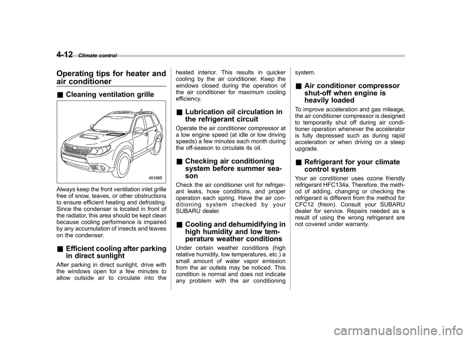
Always keep the front ventilation inlet grille
free of snow, leaves, or other obstructions
to ensure efficient heating and defrosting.
Since the condenser is located in front of
the radiator, this area should be kept clean
because cooling performance is impaired
by any accumulation of insects and leaves
on the condenser. &Efficient cooling after parking
in direct sunlight
After parking in direct sunlight, drive with
the windows open for a few minutes to
allow outside air to circulate into the heated interior. This results in quicker
cooling by the air conditioner. Keep the
windows closed during the operation of
the air conditioner for maximum cooling
efficiency.
& Lubrication oil circulation in
the refrigerant circuit
Operate the air conditioner compressor at
a low engine speed (at idle or low driving
speeds) a few minutes each month during
the off-season to circulate its oil. & Checking air conditioning
system before summer sea-son
Check the air conditioner unit for refriger-
ant leaks, hose conditions, and proper
operation each spring. Have the air con-
ditioning system checked by your
SUBARU dealer. & Cooling and dehumidifying in
high humidity and low tem-
perature weather conditions
Under certain weather conditions (high
relative humidity, low temperatures, etc.) a
small amount of water vapor emission
from the air outlets may be noticed. This
condition is normal and does not indicate
any problem with the air conditioning system. &
Air conditioner compressor
shut-off when engine is
heavily loaded
To improve acceleration and gas mileage,
the air conditioner compressor is designed
to temporarily shut off during air condi-
tioner operation whenever the accelerator
is fully depressed such as during rapid
acceleration or when driving on a steepupgrade. & Refrigerant for your climate
control system
Your air conditioner uses ozone friendly
refrigerant HFC134a. Therefore, the meth-
od of adding, changing or checking the
refrigerant is different from the method for
CFC12 (freon). Consult your SUBARU
dealer for service. Repairs needed as a
result of using the wrong refrigerant are
not covered under warranty.
Page 218 of 402
Fuel...................................................................... 7-2
Fuel requirements ............................................... 7-2
Fuel filler lid and cap ........................................... 7-3
State emission testing (U.S. only) ...................... 7-6
Preparing to drive ............................................... 7-7
Starting the engine .............................................. 7-7
Manual transmission model ................................. 7-7
Automatic transmission model ............................ 7-8
Stopping the engine ............................................ 7-9
Remote engine start system (dealer option) ................................................. 7-10
Starting your vehicle .......................................... 7-10
Remote start safety features ............................... 7-10
Entering the vehicle while it is running via remote start ................................................................. 7-11
Entering the vehicle following remote engine start shutdown ......................................................... 7-11
Pre-heating or pre-cooling the interior of the vehicle ............................................................. 7-11
Service mode ..................................................... 7-11
Remote transmitter programming and programmable feature option ............................ 7-11
System maintenance .......................................... 7-12
Manual transmission .......................................... 7-14
Shifting speeds .................................................. 7-14
Driving tips ........................................................ 7-15
Automatic transmission ..................................... 7-15
Select lever ........................................................ 7-16
Shift lock function .............................................. 7-17
Selection of manual mode .................................. 7-19
Driving tips ........................................................ 7-20 SPORT mode
..................................................... 7-20
Power steering ................................................... 7-21
Braking ............................................................... 7-21
Braking tips ....................................................... 7-21
Brake system .................................................... 7-22
Disc brake pad wear warning indicators ............. 7-22
ABS (Anti-lock Brake System) .......................... 7-23
ABS system self-check ...................................... 7-23
ABS warning light .............................................. 7-23
Electronic Brake Force Distribution (EBD) system ............................................................. 7-24
Steps to take if EBD system malfunctions ..... ..... 7-25
Vehicle Dynamics Control system .................... 7-26
Vehicle Dynamics Control system monitor..... ..... 7-27
Vehicle Dynamics Control OFF switch ................ 7-29
Tire pressure monitoring system (TPMS) (U.S.-spec. models). ........................................ 7-30
Parking your vehicle ......................................... 7-31
Parking brake .................................................... 7-31
Parking tips ....................................................... 7-32
Hill start assist system (MT models) ................ 7-33
Hill start assist warning light .............................. 7-34
Cruise control .................................................... 7-34
To set cruise control .......................................... 7-35
To temporarily cancel the cruise control ............. 7-35
To turn off the cruise control .............................. 7-36
To change the cruising speed .. .......................... 7-36
Cruise control indicator light .............................. 7-37
Cruise control set indicator light ........................ 7-38
Starting and operating
7
Page 228 of 402

&Entering the vehicle while it
is running via remote start
1. Unlock the vehicle doors using the
keyless entry system. If the vehicle ’s
doors are unlocked manually using the
key, the vehicle ’s alarm system will trigger
and the remote engine start system will
turn off. Inserting the key into the ignition
switch and turning it to the “ON ”position or
pressing the unlock button “
”on the
remote keyless entry transmitter will dis-
arm the alarm system. Refer to “Alarm
system ”F 2-14.
2. Enter the vehicle. Do not depress the
brake pedal.
3. Insert the key into the ignition switch
and turn to the “ON ”position. If the ignition
switch is accidentally turned to the“ START ”position, the system ’s “starter
anti-grind ”feature will prevent the starter
from re-cranking.
4. Depress the brake pedal. The remote
starter disengages, the vehicle ’s power
window features are re-enabled and the
vehicle will operate normally.
& Entering the vehicle follow-
ing remote engine start shut-down
An alarm trigger may occur if the vehicle is
opened by the remote keyless entry transmitter within a few seconds immedi-
ately following remote engine start shut-down.
& Pre-heating or pre-cooling
the interior of the vehicle
Before exiting the vehicle, set the tem-
perature controls to the desired setting
and operation. After the system starts the
vehicle, the heater or air-conditioning will
activate and heat or cool the interior to
your setting. & Service mode
In service mode, the remote start function
is temporarily disabled to prevent the
system from unexpectedly starting the
engine while being serviced. ! To engage the service mode
Turn the ignition switch to the “ON ”
position, depress and hold the brake
pedal, then press and release the “
”
button on the remote control transmitter
three times. The system will pause for 1
second and then flash the turn signal
lights and honk the horn three times
indicating that the system is in service
mode. When attempting to activate the
remote start system while in service
mode, the turn signal lights will flash and
the horn will honk two times and will not start. !
To disengage the service mode
Turntheignitionswitchtothe “ON ”
position, depress and hold the brake
pedal, then press and release the “
”
button on the remote control transmitter
three times. The system will pause for 1
second and flash the turn signal lights 1
time indicating that the system has exited
service mode.
NOTE
When taking your vehicle in for service,
it is recommended that you inform the
service personnel that your vehicle is
equipped with a remote control startsystem. & Remote transmitter program-
ming and programmable fea-
ture option
New transmitters can be programmed to
the engine starter system in the event that
remote transmitters are lost, stolen or
damaged. The remote engine start system
also has one programmable feature that
can be adjusted for user preference.
The remote engine starter system can be
programmed to either make an audible
horn chirp upon remote start activation or
not. Remote transmitter programming and Starting and operating
7-11
– CONTINUED –
Page 291 of 402
9-10In case of emergency
Jump starting
WARNING
. Battery fluid is SULFURIC ACID.
Do not let it come in contact with
the eyes, skin, clothing or thevehicle.
If battery fluid gets on you,
thoroughly flush the exposed
area with water immediately. Get
medical help if the fluid has
entered your eyes.
If battery fluid is accidentally
swallowed, immediately drink a
large amount of milk or water,
and obtain immediate medicalhelp.
Keep everyone including chil-
dren away from the battery.
. The gas generated by a battery
explodes if a flame or spark is
brought near it. Do not smoke or
light a match while jump starting.
. Never attempt jump starting if the
discharged battery is frozen. It
could cause the battery to burst
or explode.
. Whenever working on or around
a battery, always wear suitable eye protectors, and remove metal
objects such as rings, bands or
other metal jewelry.
. Be sure the jumper cables and
clamps on them do not have
loose or missing insulation.
Do not jump start unless cables
in suitable condition are avail-able.
. A running engine can be danger-
ous. Keep your fingers, hands,
clothing, hair and tools away
from the cooling fan, belts and
any other moving engine parts.
Removing rings, watches and
ties is advisable.
. Jump starting is dangerous if it
done incorrectly. If you are un-
sure about the proper procedure
for jump starting, consult a com-
petent mechanic.
When your vehicle does not start due to a
run down (discharged) battery, the vehicle
may be jump started by connecting your
battery to another battery (called the
booster battery) with jumper cables. &
How to jump start
1. Make sure the booster battery is 12
volts and the negative terminal isgrounded.
2. If the booster battery is in another
vehicle, do not let the two vehicles touch.
3. Turn off all unnecessary lights and accessories.
4. Connect the jumper cables exactly in
the sequence illustrated.