heating SUBARU FORESTER 2010 SH / 3.G Owners Manual
[x] Cancel search | Manufacturer: SUBARU, Model Year: 2010, Model line: FORESTER, Model: SUBARU FORESTER 2010 SH / 3.GPages: 402, PDF Size: 14.36 MB
Page 5 of 402
2
Chapter 4: Climate control
This chapter informs you how to operate
the climate control.
Chapter 5: Audio
This chapter informs you how to operate
your audio system.
Chapter 6: Interior equipment
This chapter informs you how to operate
interior equipment.
Chapter 7: Starting and operating
This chapter informs you how to start and
operate your SUBARU.
Chapter 8: Driving tips
This chapter informs you how to drive your
SUBARU in various conditions and ex-
plains some safety tips on driving.
Chapter 9: In case of emergency
This chapter informs you what to do if you
have a problem while driving, such as a
flat tire or engine overheating.
Chapter 10: Appearance care
This chapter informs you how to keep your
SUBARU looking good.
Chapter 11: Maintenance and service
This chapter informs you when you need
to take your SUBARU to the dealer for
scheduled maintenance and informs you
how to keep your SUBARU running
properly.Chapter 12: Specifications
This chapter informs you about dimen-
sions and capacities of your SUBARU.
Chapter 13: Consumer information and
Reporting safety defects
This chapter informs you about Uniform
tire quality grading standards and Report-
ing safety defects.
Chapter 14: Index
This is an alphabetical listing of all that
’sin
this manual. You can use it to quickly find
something you want to read.
& Safety warnings
You will find a number of WARNINGs,
CAUTIONs and NOTEs in this manual.
These safety warnings alert you to poten-
tial hazards that could result in injury to
you or others.
Please read these safety warnings as well
as all other portions of this manual care-
fully in order to gain a better understand-
ing of how to use your SUBARU vehicle
safely.
WARNING
A WARNING indicates a situation in
which serious injury or death could
result if the warning is ignored.
CAUTION
A CAUTION indicates a situation in
which injury or damage to your
vehicle, or both, could result if the
caution is ignored.
NOTE
A NOTE gives information or sugges-
tions how to make better use of yourvehicle. & Safety symbol
You will find a circle with a slash through it
in this manual. This symbol means “Do
not ”, “Do not do this ”,or “Do not let this
happen ”, depending upon the context.
Page 124 of 402

take several driving trips. If the light does
not turn off, take your vehicle to your
authorized SUBARU dealer immediately. !If the light is blinking
If the light is blinking while driving, an
engine misfire condition has been de-
tected which may damage the emission
control system.
To prevent serious damage to the emis-
sion control system, you should do thefollowing. . Reduce vehicle speed.
. Avoid hard acceleration.
. Avoid steep uphill grades.
. Reduce the amount of cargo, if possi-
ble.
The CHECK ENGINE warning light may
stop blinking and illuminate steadily after
several driving trips. You should have your
vehicle checked by an authorized
SUBARU dealer immediately. &
Coolant temperature
low indicator light/Cool-
ant temperature high
warning light
CAUTION
. After turning the ignition switch
to the “ON ”position, if this
indicator light/warning light be-
haves under any of the following
conditions, the electrical system
may be malfunctioning. Contact
your SUBARU dealer immedi-
ately for an inspection. – It remains blinking in RED.
– It remains illuminated in RED
for more than 2 seconds.
– It remains blinking in RED and
BLUE alternately.
. While driving, if this indicator
light/warning light behaves under
any of the following conditions,
take the specified appropriate
measure listed below. – Blinking or illuminated in
RED:
Safely stop the vehicle as
soon as possible, and refer
to the emergency steps for the
engine overheating. After- ward, have the system
checked by your nearest
SUBARU dealer. Refer to
“En-
gine overheating ”F 9-12.
– Blinking in RED and BLUE
alternately:
The electrical system may be
malfunctioning. Contact your
SUBARU dealer for an inspec-tion.
This coolant temperature low indicator
light/coolant temperature high warning
light has the following three functions. . Illumination in BLUEindicates insuffi-
cient warming up of the engine. Blinking in REDindicates that the
engine is close to overheating. Illumination in REDindicates overheat-
ing condition of the engine
For the system check, this indicator light/
warning light illuminates in REDfor
approximately 2 seconds when the igni-
tion switch is turned to the “ON ”position.
After that, this indicator light/warning light
changes to BLUEand maintains illumina-
tion in BLUE. This BLUE illuminated light
turns off when the engine is warmed up
sufficiently.
If the engine coolant temperature in- Instruments and controls
3-13
– CONTINUED –
Page 125 of 402
3-14Instruments and controls
creases over the specified range, the
indicator light/warning light blinks inRED. At this time, the engine is close to
overheating.
If the engine coolant temperature in-
creases further, the indicator light/warning
light illuminates in REDcontinuously. At
this time, the engine may be overheating.
When the indicator light/warning light
blinks in REDor illuminates in RED, safely
stop the vehicle as soon as possible, and
refer to the emergency steps for the
engine overheating. Refer to “Engine
overheating ”F 9-12. Afterward, have the
system checked by your nearest
SUBARU dealer.
Also, if the indicator light/warning light
often blinks in RED, the electrical system
may be malfunctioning. Contact your
SUBARU dealer for an inspection.
NOTE
If the engine is restarted after a certain
driving condition, this indicator light/
warning light may illuminate in RED.
However, this is not a malfunction if the
indicator light/warning light turns off
after a short time. &
Charge warning light
If this light illuminates when the engine is
running, it may indicate that the charging
system is not working properly.
If the light illuminates while driving or does
not turn off after the engine starts, stop the
engine at the first safe opportunity and
check the alternator belt. If the belt is
loose, broken or if the belt is in good
condition but the light remains on, contact
your nearest SUBARU dealer immedi-
ately. &Oil pressure warning light
If this light illuminates when the engine is
running, it may indicate that the engine oil
pressure is low and the lubricating system
is not working properly.
If the light illuminates while driving or does
not turn off after the engine starts, stop the
engine at the first safe opportunity and
check the engine oil level. If the oil level is
low, add oil immediately. If the engine oil is
at the proper level but the light remains on,
contact your nearest SUBARU dealer
immediately.
CAUTION
Do not operate the engine with the
oil pressure warning light on. This
may cause serious engine damage.
& AT OIL TEMP warning
light (AT models)
The AT oil temperature warning light “AT
OIL TEMP ”illuminates when the ignition
switch is turned to the “ON ”position and
turns off after the engine has started.
If this light illuminates when the engine is
running, it may indicate that the automatic
transmission fluid temperature is too hot.
If the light illuminates while driving, im-
mediately stop the vehicle in a safe place
and let the engine idle until the warning
light turns off. ! Automatic transmission control
system warning
If the light flashes after the engine starts, it
may indicate that the automatic transmis-
sion control system is not working prop-
erly. Contact your nearest SUBARU deal-
er for service immediately.
Page 140 of 402
Wiper and washer
WARNING
In freezing weather, do not use the
windshield washer until the wind-
shield is sufficiently warmed by the
defroster.
Otherwise the washer fluid can
freeze on the windshield, blocking
your view.
CAUTION
. Do not operate the washer con-
tinuously for more than 10 sec-
onds, or when the washer fluid
tank is empty. This may cause
overheating of the washer motor.
Check the washer fluid level
frequently, such as at fuel stops.
. Do not operate the wipers when
the windshield or rear window is
dry. This may scratch the glass,
damage the wiper blades and
cause the wiper motor to burn
out. Before operating the wiper
on a dry windshield or rear
window, always use the wind-
shield washer. .
In freezing weather, be sure that
the wiper blades are not frozen to
the windshield or rear window
before switching on the wipers.
Attempting to operate the wiper
with the blades frozen to the
window glass could cause not
only the wiper blades to be
damaged but also the wiper mo-
tor to burn out. If the wiper
blades are frozen to the window
glass, be sure to operate the
defroster, windshield wiper dei-
cer (if equipped) or rear window
defogger before turning on the
wiper.
. If the wipers stop during opera-
tion because of ice or some other
obstruction on the window, the
wiper motor could burn out even
if the wiper switch is turned off. If
this occurs, promptly stop the
vehicle in a safe place, turn the
ignition switch to the “LOCK ”
position and clean the window
glass to allow proper wiper op-eration.
. Use clean water if windshield
washer fluid is unavailable. In
areas where water freezes in
winter, use SUBARU Windshield
Washer Fluid or the equivalent. Refer to
“Windshield washer
fluid ”F 11-38.
Also, when driving the vehicle
when there are freezing tempera-
tures, use non-freezing type wi-
per blades.
. Do not clean the wiper blades
with gasoline or a solvent, such
as paint thinner or benzine. This
will cause deterioration of the
wiper blades.
NOTE . The wiper operates only when the
ignition switch is in the “ON ”or “Acc ”
position. . The front wiper motor is protected
against overloads by a circuit breaker.
If the motor operates continuously
under an unusually heavy load, the
circuit breaker may trip to stop the
motor temporarily. If this happens, park
your vehicle in a safe place, turn off the
wiper switch, and wait for approxi-
mately 10 minutes. The circuit breaker
will reset itself, and the wipers will
again operate normally.. Clean your wiper blades and win-
dow glass periodically with a washer
solution to prevent streaking, and to
remove accumulations of road salt or Instruments and controls
3-29
– CONTINUED –
Page 160 of 402
WARNING
Continued operation with the air
inletselectionbuttonintheON
position may fog up the windows.
Switch to the OFF position as soon
as the outside dusty conditionclears.
& Heater operation
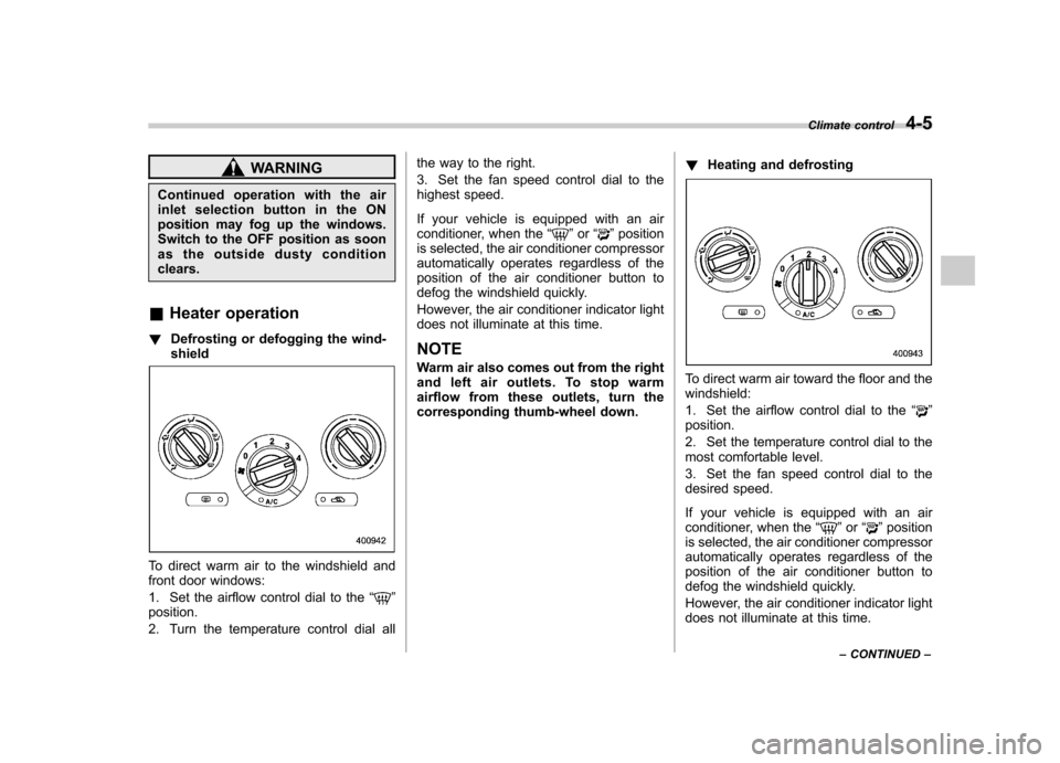
! Defrosting or defogging the wind-shield
To direct warm air to the windshield and
front door windows:
1. Set the airflow control dial to the “
”
position.
2. Turn the temperature control dial all the way to the right.
3. Set the fan speed control dial to the
highest speed.
If your vehicle is equipped with an air
conditioner, when the
“
”or “”position
is selected, the air conditioner compressor
automatically operates regardless of the
position of the air conditioner button to
defog the windshield quickly.
However, the air conditioner indicator light
does not illuminate at this time. NOTE
Warm air also comes out from the right
and left air outlets. To stop warm
airflow from these outlets, turn the
corresponding thumb-wheel down. !
Heating and defrosting
To direct warm air toward the floor and the windshield:
1. Set the airflow control dial to the “
”
position.
2. Set the temperature control dial to the
most comfortable level.
3. Set the fan speed control dial to the
desired speed.
If your vehicle is equipped with an air
conditioner, when the “
”or “”position
is selected, the air conditioner compressor
automatically operates regardless of the
position of the air conditioner button to
defog the windshield quickly.
However, the air conditioner indicator light
does not illuminate at this time. Climate control
4-5
– CONTINUED –
Page 161 of 402
4-6Climate control
NOTE
Warm air also comes out from the right
andleftairoutlets.Tostopwarm
airflow from these outlets, turn the
corresponding thumb-wheel down. ! Heating
To direct warm air toward the floor:
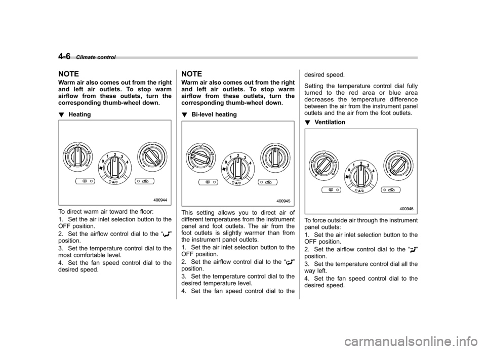
1. Set the air inlet selection button to the
OFF position.
2. Set the airflow control dial to the “
”
position.
3. Set the temperature control dial to the
most comfortable level.
4. Set the fan speed control dial to the
desired speed. NOTE
Warm air also comes out from the right
and left air outlets. To stop warm
airflow from these outlets, turn the
corresponding thumb-wheel down. !
Bi-level heating
This setting allows you to direct air of
different temperatures from the instrument
panel and foot outlets. The air from the
foot outlets is slightly warmer than from
the instrument panel outlets.
1. Set the air inlet selection button to the
OFF position.
2. Set the airflow control dial to the “
”
position.
3. Set the temperature control dial to the
desired temperature level.
4. Set the fan speed control dial to the desired speed.
Setting the temperature control dial fully
turned to the red area or blue area
decreases the temperature difference
between the air from the instrument panel
outlets and the air from the foot outlets. !
Ventilation
To force outside air through the instrument
panel outlets:
1. Set the air inlet selection button to the
OFF position.
2. Set the airflow control dial to the “
”
position.
3. Set the temperature control dial all the
way left.
4. Set the fan speed control dial to the
desired speed.
Page 164 of 402

&Fan speed control dial
The fan operates only with the ignition
switch in the ON position. The fan speed
control dial is used to select the AUTO
(automatic control) mode or to select the
desired fan speed. The dial ’s positions
and their functions are as follows. OFF: The fan does not operate.
AUTO: The fan speed is adjusted auto-
maticallyinaccordancewiththeair
temperature inside and outside the pas-
senger compartment, the intensity of sun-
light, and other factors. SUBARU recom-
mends using the AUTO position.
Other positions: The fan speed can be
adjusted in 7 steps. NOTE
With the fan speed control dial in the
AUTO position and the airflow control
dial in the
“
”, “”,or “”position,
the fan does not operate during engine
warm-up until the engine coolant tem-
perature exceeds approximately 122 8F
(50 8C).
& Temperature control dial
This dial is used to set the desired interior
temperature. With the dial set to your
desired temperature, the system automa-
tically adjusts the temperature of air
supplied from the outlets such that the
desired temperature is achieved andmaintained.
If the dial is turned fully counterclockwise, the system gives maximum cooling per-
formance. If the dial is turned fully clock-
wise, the system gives maximum heatingperformance. &
Airflow control dial
The dial has six positions that activate the
following outlets. AUTO: The airflow control is adjusted
automatically in accordance with the air
temperature inside and outside the pas-
senger compartment, the intensity of sun-
light, and other factors. SUBARU recom-
mends using the AUTO position.
(Ventilation): Instrument panel outlets
(Bi-level): Instrument panel outlets and
foot outlets Climate control
4-9
– CONTINUED –
Page 167 of 402
4-12Climate control
Operating tips for heater and
air conditioner &Cleaning ventilation grille
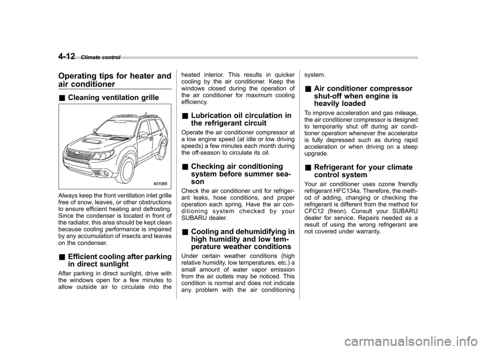
Always keep the front ventilation inlet grille
free of snow, leaves, or other obstructions
to ensure efficient heating and defrosting.
Since the condenser is located in front of
the radiator, this area should be kept clean
because cooling performance is impaired
by any accumulation of insects and leaves
on the condenser. &Efficient cooling after parking
in direct sunlight
After parking in direct sunlight, drive with
the windows open for a few minutes to
allow outside air to circulate into the heated interior. This results in quicker
cooling by the air conditioner. Keep the
windows closed during the operation of
the air conditioner for maximum cooling
efficiency.
& Lubrication oil circulation in
the refrigerant circuit
Operate the air conditioner compressor at
a low engine speed (at idle or low driving
speeds) a few minutes each month during
the off-season to circulate its oil. & Checking air conditioning
system before summer sea-son
Check the air conditioner unit for refriger-
ant leaks, hose conditions, and proper
operation each spring. Have the air con-
ditioning system checked by your
SUBARU dealer. & Cooling and dehumidifying in
high humidity and low tem-
perature weather conditions
Under certain weather conditions (high
relative humidity, low temperatures, etc.) a
small amount of water vapor emission
from the air outlets may be noticed. This
condition is normal and does not indicate
any problem with the air conditioning system. &
Air conditioner compressor
shut-off when engine is
heavily loaded
To improve acceleration and gas mileage,
the air conditioner compressor is designed
to temporarily shut off during air condi-
tioner operation whenever the accelerator
is fully depressed such as during rapid
acceleration or when driving on a steepupgrade. & Refrigerant for your climate
control system
Your air conditioner uses ozone friendly
refrigerant HFC134a. Therefore, the meth-
od of adding, changing or checking the
refrigerant is different from the method for
CFC12 (freon). Consult your SUBARU
dealer for service. Repairs needed as a
result of using the wrong refrigerant are
not covered under warranty.
Page 168 of 402
Air filtration system
Replace the filter element according to the
replacement schedule as follows. This
schedule should be followed to maintain
the filter’s dust collection ability. Under
extremely dusty conditions, the filter
should be replaced more frequently. It is
recommended that you have your filter
checked or replaced by your SUBARU
dealer. For replacement, use only a
genuine SUBARU air filter kit.
Replacement schedule: Every 12 months or 7,500 miles (12,000
km) whichever comes first
CAUTION
Contact your SUBARU dealer if the
following occurs, even if it is not yet
time to change the filter. – Reduction of the airflow through
the vents.
– Windshield gets easily fogged ormisted.
NOTE
The filter can influence the air condi-
tioning, heating and defroster perfor- mance if not properly maintained.
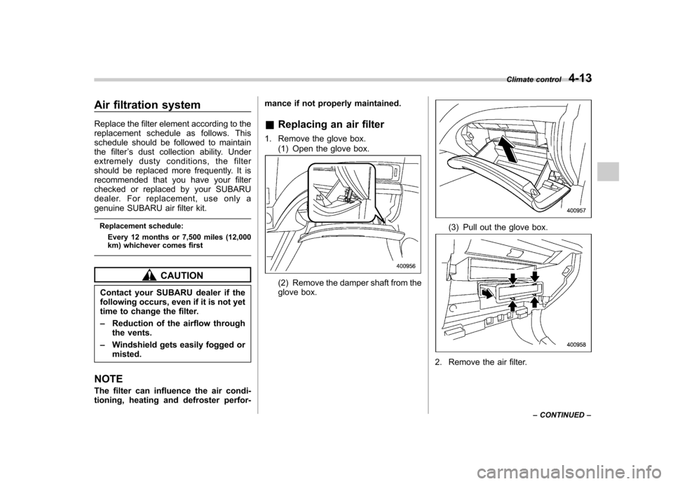
& Replacing an air filter
1. Remove the glove box. (1) Open the glove box.(2) Remove the damper shaft from the
glove box.
(3) Pull out the glove box.
2. Remove the air filter. Climate control
4-13
– CONTINUED –
Page 212 of 402
&Use with a cigarette lighter
(dealer option)
To use the accessory power outlet as a
cigarette lighter socket, purchase the
cigarette lighter plug, which is an optional
accessory.
A cigarette lighter plug is available from
your SUBARU dealer.
The cigarette lighter operates only when
the ignition switch is in the “ON ”or “Acc ”
position.
To use the cigarette lighter, push in the
knob and wait a few moments. It will
automatically spring up when ready foruse.
WARNING
To avoid being burned, never grasp
the lighter by the end with the
heating element. Doing so could
result in injury and could also
damage the heating element.
CAUTION
. Do not hold the lighter pushed in,
because it will overheat.
. Do not use a non-genuine cigar-
ette lighter plug in the socket.
Doing so may cause a short- circuit and overheating, resulting
in a fire.
. If the socket is ever used for a
plug-in accessory such as a cell
phone, that may damage the
portion of the socket ’s internal
mechanism that causes a cigar-
ette lighter plug to “pop out ”
after its lighter element is heated.
Therefore, do not place a cigar-
ette lighter plug in a socket that
has been used, even once, to
power a plug-in accessory. Doing
so may cause the plug to stick
and overheat, creating a potential
fire hazard. Ashtray (if equipped)
CAUTION
Do not use ashtrays as waste re-
ceptacles or leave a lighted cigarette
in an ashtray. This could cause afire.
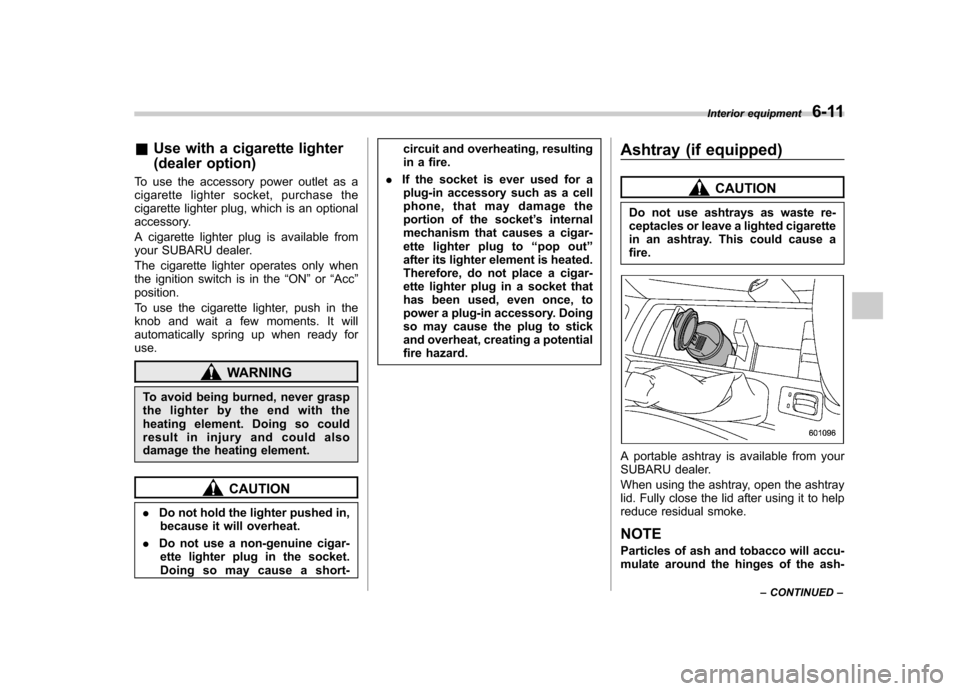
A portable ashtray is available from your
SUBARU dealer.
When using the ashtray, open the ashtray
lid. Fully close the lid after using it to help
reduce residual smoke. NOTE
Particles of ash and tobacco will accu-
mulate around the hinges of the ash- Interior equipment
6-11
– CONTINUED –