instruments SUBARU FORESTER 2017 SJ / 4.G Owners Manual
[x] Cancel search | Manufacturer: SUBARU, Model Year: 2017, Model line: FORESTER, Model: SUBARU FORESTER 2017 SJ / 4.GPages: 634, PDF Size: 11.77 MB
Page 6 of 634
Warranties
&Warranties for U.S.A.
All SUBARU vehicles distributed by
Subaru of America, Inc. and sold at retail
by an authorized SUBARU dealer in the
United States come with the following
warranties:
. SUBARU Limited Warranty
. Emission Control Systems Warranty
. Emissions Performance Warranty
All warranty information, including details
of coverage and exclusions, is in the
“ Warranty and Maintenance Booklet ”.
Read these warranties carefully.
& Warranties for Canada
All SUBARU vehicles distributed by
Subaru Canada, Inc. and sold at retail by
an authorized SUBARU dealer in Canada
come with the following warranties:
. SUBARU Limited Warranty
. Anti-Corrosion Warranty
. Emission Control Warranty
All warranty information, including details
of coverage and exclusions, is in the
“ Warranty and Service Booklet ”. Read
these warranties carefully.
& Warranties except for U.S.A.
and Canada
All warranty information, including details
of coverage and exclusions, is in the
“Warranty and Maintenance Booklet ”.
Read these warranties carefully.
How to use this Owner ’s
Manual
& Using your Owner ’s Manual
Before you operate your vehicle, carefully
read this manual. To protect yourself and
extend the service life of your vehicle,
follow the instructions in this manual.
Failure to observe these instructions may
result in serious injury and damage to your
vehicle.
This manual is composed of fourteen
chapters. Each chapter begins with a brief
table of contents, so you can usually tell at
a glance if that chapter contains the
information you want.
Chapter 1: Seat, seatbelt and SRS
airbags
This chapter informs you how to use the
seat and seatbelt and contains precau-
tions for the SRS airbags.
Chapter 2: Keys and doors
This chapter informs you how to operate
the keys, locks and windows.
Chapter 3: Instruments and controls
This chapter informs you about the opera-
tion of instrument panel indicators and
how to use the instruments and other
switches.
– CONTINUED –
1
Page 16 of 634
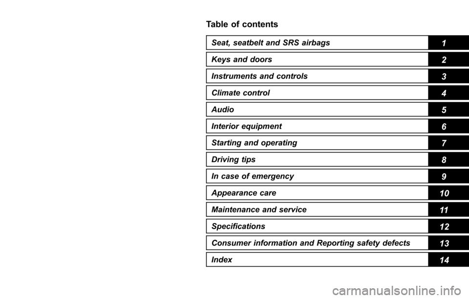
Table of contents
Seat, seatbelt and SRS airbags1
Keys and doors2
Instruments and controls
Climate control4
Audio5
Interior equipment6
Starting and operating7
Driving tips8
In case of emergency9
Appearance care10
Maintenance and service11
Specifications12
Consumer information and Reporting safety defects13
Index14
3
Page 152 of 634
Ignition switch (models without push-button start system) ......................................... 3-4
LOCK.................................................................. 3-4
ACC.................................................................... 3-5
ON...................................................................... 3-5
START ................................................................ 3-5
Key reminder chime ............................................ 3-5
Ignition switch light (if equipped) ......................... 3-6
Push-button ignition switch (models with
push-button start system) ............................... 3-6
Safety precautions.............................................. 3-6
Operating range for push-button start system ...... 3-6
Switching power status ....................................... 3-7
When access key does not operate properly ........ 3-8
Hazard warning flasher....................................... 3-8
Meters and gauges. ............................................. 3-9
Combination meter illumination ........................... 3-9
Canceling the function for meter/gauge needle movement upon turning on the ignition
switch ............................................................... 3-9
Speedometer ...................................................... 3-10
Odometer ........................................................... 3-10
Double trip meter ............................................... 3-10
Tachometer ........................................................ 3-11
Fuel gauge ......................................................... 3-12
ECO gauge (if equipped) .................................... 3-12
Warning and indicator lights ............................. 3-13Seatbelt warning light and chime ........................ 3-14
SRS airbag system warning light ........................ 3-15
Front passenger ’s frontal airbag ON and OFF
indicators ......................................................... 3-16 CHECK ENGINE warning light/Malfunction
indicator light .................................................. 3-16
Coolant temperature low indicator light/Coolant temperature high warning light ......................... 3-17
Charge warning light .......................................... 3-18
Oil pressure warning light .................................. 3-18
Engine low oil level warning light ....................... 3-18
Windshield washer fluid warning light ................ 3-19
AT OIL TEMP warning light (CVT models) ........... 3-19
Low tire pressure warning light (U.S.-spec. models) ........................................................... 3-19
ABS warning light .............................................. 3-21
Brake system warning light ................................ 3-21
Low fuel warning light ....................................... 3-22
Hill start assist warning light/Hill start assist OFF indicator light .................................................. 3-23
Door open warning light .................................... 3-23
All-Wheel Drive warning light (CVT models) ... ..... 3-23
Power steering warning light .............................. 3-23
Vehicle Dynamics Control warning light/Vehicle Dynamics Control operation indicator light .. ..... 3-24
Vehicle Dynamics Control OFF indicator light ..... 3-25
Warning chimes and warning light of the keyless access with push-button start system (if
equipped) ........................................................ 3-25
Security indicator light ....................................... 3-30
SI-DRIVE indicator light (if equipped) .................. 3-31
Select lever/gear position indicator (CVT models) ........................................................... 3-31
Turn signal indicator lights ................................. 3-32
High beam indicator light ................................... 3-32
High beam assist indicator light (if equipped) ..... 3-32
Instruments and controls
3
Page 153 of 634
Instruments and controls
Cruise control indicator light (if equipped).......... 3-32
Cruise control set indicator light (if equipped) ......................................................... 3-32
Automatic headlight beam leveler warning light (if equipped) ......................................................... 3-32
Steering Responsive Headlight warning light/ Steering Responsive Headlight OFF indicator
light (if equipped) ............................................. 3-33
Front fog light indicator light (if equipped) .......... 3-33
Headlight indicator light (if equipped) ................. 3-33
X-mode indicator light (if equipped) .................... 3-33
Hill descent control indicator light (if equipped) ......................................................... 3-33
Steering responsive fog lights warning indicator/ Steering responsive fog lights OFF indicator (if
equipped) ......................................................... 3-33
BSD/RCTA warning indicator (if equipped) .......... 3-33
BSD/RCTA OFF indicator (if equipped) ................ 3-34
RAB warning light (if equipped) .......................... 3-34
RAB OFF indicator light (if equipped) .................. 3-34
Information display (Mexico-spec. models) ...... 3-34Outside temperature indicator............................ 3-34
Driving information display ................................. 3-35
Clock ................................................................. 3-38
Multi information display (models with type
B combination meter) ..................................... 3-39
Basic operation.................................................. 3-40
Welcome screen and Good-bye screen ............... 3-40
Warning screen .................................................. 3-41
Basic screens .................................................... 3-41
Menu screens .................................................... 3-42
Multi function display (if equipped) .................. 3-44Basic operation................................................. 3-45
Welcome screen ................................................ 3-45
Ending screen ................................................... 3-46
Self-check screen .............................................. 3-46
Interruption screen ............................................ 3-48
Basic screens .................................................... 3-48
Selection screen ................................................ 3-56
Date and time settings ....................................... 3-59
Image quality and volume settings ..................... 3-66
Screen settings. ................................................. 3-68
Maintenance settings ......................................... 3-76
Driving history registration ................................. 3-79
Car settings ....................................................... 3-80
Initialize ............................................................. 3-90
Light control switch ........................................... 3-93Headlights......................................................... 3-93
High/low beam change (dimmer) ... ..................... 3-95
Headlight flasher ............................................... 3-98
Daytime running light system ............................. 3-98
Steering Responsive Headlight (SRH) (if
equipped) ........................................................ 3-99
SRH OFF switch ................................................ 3-99
Turn signal lever .............................................. 3-100One-touch lane changer ................................... 3-101
Illumination brightness control ....................... 3-101
Headlight beam leveler (if equipped) ............. 3-102
Automatic headlight beam leveler (models with
LED headlights) ............................................. 3-102
Page 154 of 634
Instruments and controls
Fog light switch (if equipped)......................... 3-102Steering responsive fog lights system (if
equipped) ....................................................... 3-103
Wiper and washer ............................................ 3-104Windshield wiper and washer switches ............. 3-105
Rear window wiper and washer switch .............. 3-106
Mirrors............................................................... 3-107Inside mirror .................................................... 3-107
Auto-dimming mirror/compass (if equipped) ...... 3-108Auto-dimming mirror/compass with HomeLink
®(if equipped)
.................................................. 3-109
Outside mirrors ............................................... 3-115
Defogger and deicer ........................................ 3-116
Tilt/telescopic steering wheel ......................... 3-118
Horn .................................................................. 3-118
Heated Steering Wheel system (if equipped) ...................................................... 3-119
Page 155 of 634
Instruments and controls/Ignition switch (models without push–button start system)
Ignition switch (models with-
out push-button start sys-
tem)
WARNING
. Never turn the ignition switch to
the “LOCK ”position while the
vehicle is being driven or towed
because that will lock the steer-
ing wheel, preventing steering
control. And when the engine is
turned off, it takes a much great-
er effort than usual to steer.
. Before leaving the vehicle, al-
ways remove the key from the
ignition switch for safety and
never allow an unattended child
to remain in the vehicle. Failure
to follow this procedure could
result in injury to a child or
others. Children could operate
the power windows, the moon-
roof or other controls or even
make the vehicle move.
CAUTION
Do not attach a large key holder or
key case to either key. If it banged
against your knees or hands while
you are driving, it could turn the
ignition switch from the “ON ”posi-
tion to the “ACC ”or “LOCK ”posi-
tion, thereby stopping the engine.
Also, if the key is attached to a
keyholder or to a large bunch of
other keys, centrifugal force may act
on it as the vehicle moves, resulting
in unwanted turning of the ignition
switch.
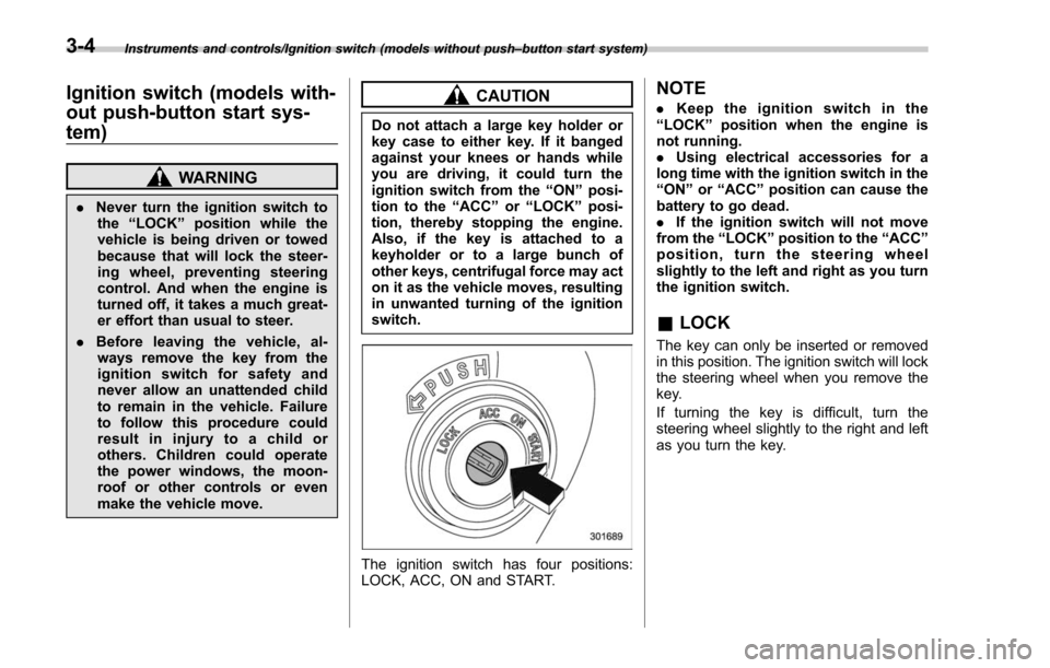
The ignition switch has four positions:
LOCK, ACC, ON and START.
NOTE
. Keep the ignition switch in the
“ LOCK ”position when the engine is
not running.
. Using electrical accessories for a
long time with the ignition switch in the
“ ON ”or “ACC ”position can cause the
battery to go dead.
. If the ignition switch will not move
from the “LOCK ”position to the “ACC ”
position, turn the steering wheel
slightly to the left and right as you turn
the ignition switch.
& LOCK
The key can only be inserted or removed
in this position. The ignition switch will lock
the steering wheel when you remove the
key.
If turning the key is difficult, turn the
steering wheel slightly to the right and left
as you turn the key.
3-4
Page 156 of 634
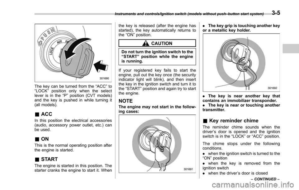
The key can be turned from the“ACC”to
“ LOCK ”position only when the select
lever is in the “P”position (CVT models)
and the key is pushed in while turning it
(all models).
& ACC
In this position the electrical accessories
(audio, accessory power outlet, etc.) can
be used.
&ON
This is the normal operating position after
the engine is started.
&START
The engine is started in this position. The
starter cranks the engine to start it. When the key is released (after the engine has
started), the key automatically returns to
the
“ON ”position.
CAUTION
Do not turn the ignition switch to the
“START ”position while the engine
is running.
If your registered key fails to start the
engine, pull out the key once (the security
indicator light will blink), and then insert
the key in the ignition switch and turn it to
the “START ”position and again try to start
the engine.
NOTE
The engine may not start in the follow-
ing cases:
. The key grip is touching another key
or a metallic key holder.
. The key is near another key that
contains an immobilizer transponder.
. The key is near or touching another
transmitter.
& Key reminder chime
The reminder chime sounds when the
driver ’s door is opened and the ignition
switch is in the “LOCK ”or “ACC ”position.
The chime stops under the following
conditions.
. when the ignition switch is turned to the
“ON ”position
. when the key is removed from the
ignition switch
. when the driver ’s door is closed
Instruments and controls/Ignition switch (models without push –button start system)
–CONTINUED –3-5
Page 157 of 634
Instruments and controls/Push–button ignition switch (models with push –button start system)
& Ignition switch light (if
equipped)
For easy access to the ignition switch in
the dark, the ignition switch light illumi-
nates when the driver ’s door is opened or
when the driver ’s door is unlocked using
the remote keyless entry transmitter.
The light remains illuminated for several
tens of seconds and then gradually turns
off under the following conditions.
. when the driver ’s door is closed
. when the doors are unlocked using the
remote keyless entry transmitter
The light turns off immediately under the
following conditions.
. when the ignition switch is turned to the
“ ON ”position
. when all doors and the rear gate are
locked using the remote keyless entry
transmitter
Push-button ignition switch
(models with push-button
start system)
& Safety precautions
Refer to “Safety precautions” F2-10.
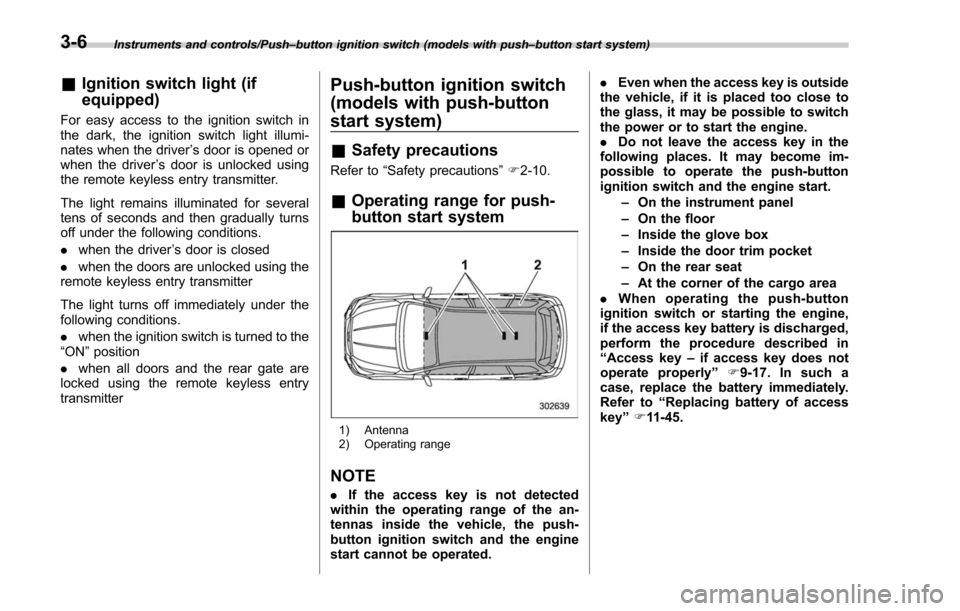
& Operating range for push-
button start system
1) Antenna
2) Operating range
NOTE
. If the access key is not detected
within the operating range of the an-
tennas inside the vehicle, the push-
button ignition switch and the engine
start cannot be operated. .
Even when the access key is outside
the vehicle, if it is placed too close to
the glass, it may be possible to switch
the power or to start the engine.
. Do not leave the access key in the
following places. It may become im-
possible to operate the push-button
ignition switch and the engine start.
–On the instrument panel
– On the floor
– Inside the glove box
– Inside the door trim pocket
– On the rear seat
– At the corner of the cargo area
. When operating the push-button
ignition switch or starting the engine,
if the access key battery is discharged,
perform the procedure described in
“ Access key –if access key does not
operate properly ”F9-17. In such a
case, replace the battery immediately.
Refer to “Replacing battery of access
key ”F 11-45.
3-6
Page 158 of 634
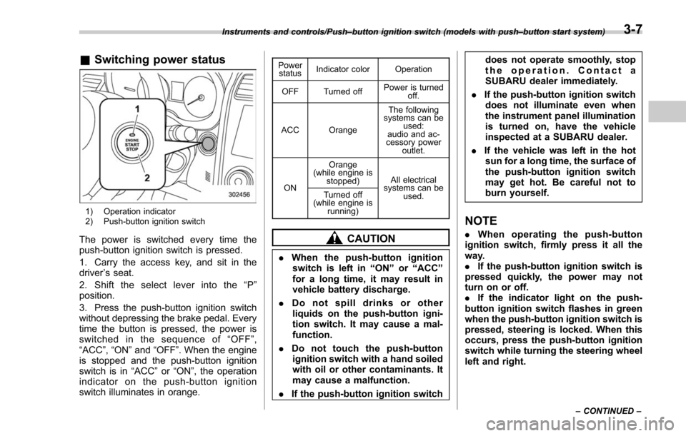
&Switching power status
1) Operation indicator
2) Push-button ignition switch
The power is switched every time the
push-button ignition switch is pressed.
1. Carry the access key, and sit in the
driver ’s seat.
2. Shift the select lever into the “P ”
position.
3. Press the push-button ignition switch
without depressing the brake pedal. Every
time the button is pressed, the power is
switched in the sequence of “OFF ”,
“ACC ”,“ON ”and “OFF ”. When the engine
is stopped and the push-button ignition
switch is in “ACC”or “ON ”, the operation
indicator on the push-button ignition
switch illuminates in orange.
Power status Indicator color Operation
OFF Turned off Power is turned
off.
ACC Orange The following
systems can be used:
audio and ac-
cessory power
outlet.
ON Orange
(while engine is stopped) All electrical
systems can be
used.
Turned off
(while engine is
running)
CAUTION
.When the push-button ignition
switch is left in “ON ”or “ACC ”
for a long time, it may result in
vehicle battery discharge.
. Do not spill drinks or other
liquids on the push-button igni-
tion switch. It may cause a mal-
function.
. Do not touch the push-button
ignition switch with a hand soiled
with oil or other contaminants. It
may cause a malfunction.
. If the push-button ignition switch does not operate smoothly, stop
the operation. Contact a
SUBARU dealer immediately.
. If the push-button ignition switch
does not illuminate even when
the instrument panel illumination
is turned on, have the vehicle
inspected at a SUBARU dealer.
. If the vehicle was left in the hot
sun for a long time, the surface of
the push-button ignition switch
may get hot. Be careful not to
burn yourself.
NOTE
. When operating the push-button
ignition switch, firmly press it all the
way.
. If the push-button ignition switch is
pressed quickly, the power may not
turn on or off.
. If the indicator light on the push-
button ignition switch flashes in green
when the push-button ignition switch is
pressed, steering is locked. When this
occurs, press the push-button ignition
switch while turning the steering wheel
left and right.
Instruments and controls/Push –button ignition switch (models with push –button start system)
–CONTINUED –3-7
Page 159 of 634
Instruments and controls/Hazard warning flasher
!Battery drainage prevention func-
tion
When the push-button ignition switch is
left in the “ACC”or “ON ”position for
approximately 1 hour, the push-button
ignition switch will be automatically
switched to “OFF”to prevent the battery
from going dead. This function is activated
when the select lever is in the “P ”position.
& When access key does not
operate properly
Refer to “Access key –if access key does
not operate properly ”F 9-17.
Hazard warning flasher
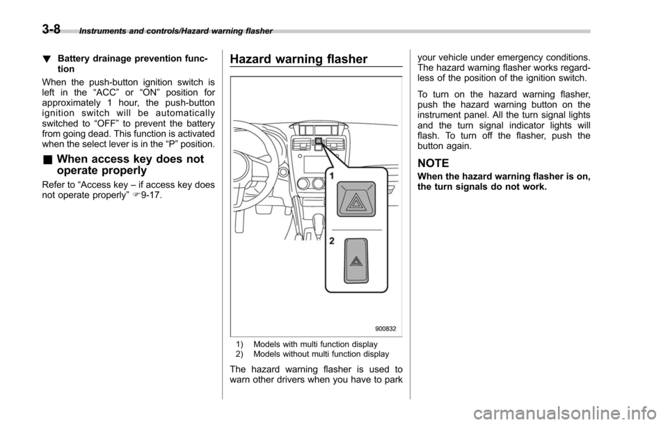
1) Models with multi function display
2) Models without multi function display
The hazard warning flasher is used to
warn other drivers when you have to park your vehicle under emergency conditions.
The hazard warning flasher works regard-
less of the position of the ignition switch.
To turn on the hazard warning flasher,
push the hazard warning button on the
instrument panel. All the turn signal lights
and the turn signal indicator lights will
flash. To turn off the flasher, push the
button again.
NOTE
When the hazard warning flasher is on,
the turn signals do not work.
3-8