battery SUBARU IMPREZA 2011 4.G Owners Manual
[x] Cancel search | Manufacturer: SUBARU, Model Year: 2011, Model line: IMPREZA, Model: SUBARU IMPREZA 2011 4.GPages: 458, PDF Size: 16.22 MB
Page 29 of 458

26
Function settings
A SUBARU dealer can change the settings of the functions shown in the following table to meet your personal requirements. Contact
the nearest SUBARU dealer for details. If your vehicle is equipped with the genuine SUBARU navigation system, the settings for some
of these functions can be changed using the navigation monitor. For details, please refer to the Owner’s Manual supplement for the
navigation system.
Item Function Possible settings Default setting Page
Alarm system Alarm system Operation/Non-operation Operation 2-16 Monitoring start delay time (after closure of doors) 0 second/30 seconds 30 seconds 2-18
Impact sensor operation (only models with
shock sensors (dealer option)) Operation/Non-operation Non-operation 2-20
Passive arming Operation/Non-operation Non-operation 2-19
Dome light and map lights illumination
(models with moonroof) ON/OFF OFF 2-16
Dome light illumination
(models without moonroof)
Remote keyless entry system Hazard warning flasher Operation/Non-operation Operation 2-8 Audible signal Operation/Non-operation Operation 2-11
Key lock-in prevention Key lock-in prevention Operation/Non-operation Operation 2-7
Remote engine start system
(dealer option) Horn chirp confirmation ON/OFF ON 7-12
Defogger and deicer system for
models with the automatic climate
control system Rear window defogger, outside mirror
defogger and windshield wiper deicer
Operation for 15 minutes/
Continuous operationOperation for 15 minutes 3-48
Dome light Operation of dome light/map light OFF delay timer OFF/Short/Normal/Long Long 6-2, 6-3
Map light for models with a moonroof
Battery drainage prevention function Battery drainage prevention function Operation/Non-operation Operation 2-5
Page 37 of 458
1-6Seat, seatbelt and SRS airbags
Seat heater (if equipped)
The seat heater is equipped in the front seats.
The seat heater operates when the igni-
tion switch is either in the “Acc ”or “ON ”
position.
CAUTION
. There is a possibility that people
with delicate skin may suffer
slight burns even at low tempera-
tures if they use the seat heater
for a long period of time. When
using the heater, always be sure
to warn the persons concerned.
. Do not put anything on the seat
which insulates against heat,
such as a blanket, cushion, or
similar items. This may cause the
seat heater to overheat.
NOTE
Use of the seat heater for a long period
of time while the engine is not running
can cause battery discharge. &
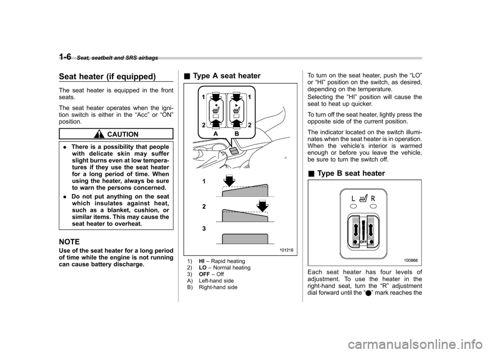
Type A seat heater
1) HI–Rapid heating
2) LO–Normal heating
3) OFF –Off
A) Left-hand side
B) Right-hand side To turn on the seat heater, push the
“LO ”
or “HI ”position on the switch, as desired,
depending on the temperature.
Selecting the “HI ”position will cause the
seat to heat up quicker.
To turn off the seat heater, lightly press the
opposite side of the current position.
The indicator located on the switch illumi-
nates when the seat heater is in operation.
When the vehicle ’s interior is warmed
enough or before you leave the vehicle,
be sure to turn the switch off.
& Type B seat heater
Each seat heater has four levels of
adjustment. To use the heater in the
right-hand seat, turn the “R ” adjustment
dial forward until the “
”mark reaches the
Page 50 of 458
CAUTION
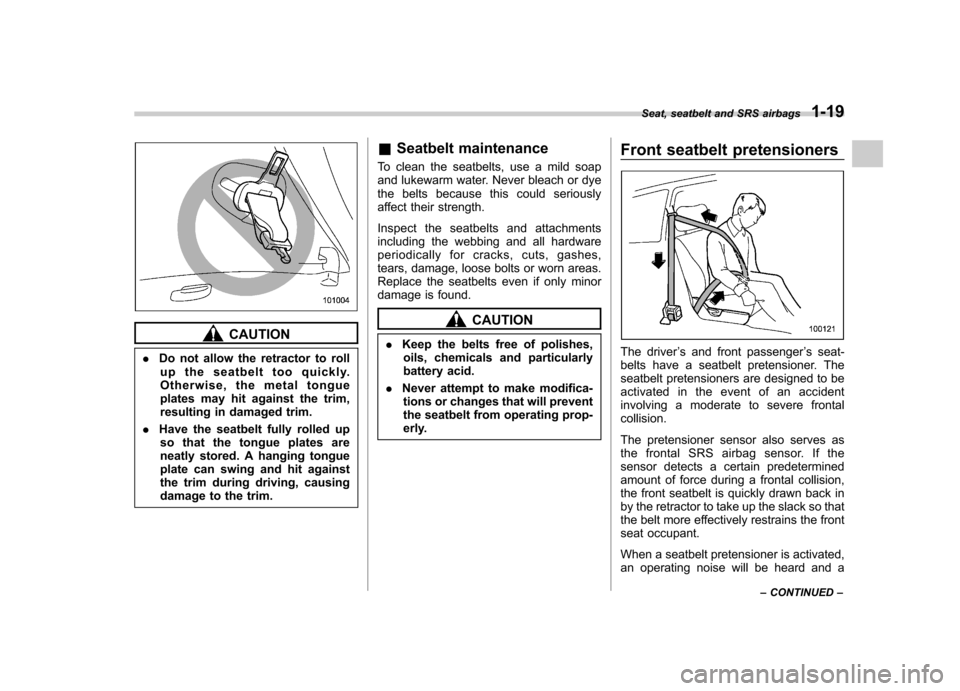
. Do not allow the retractor to roll
up the seatbelt too quickly.
Otherwise, the metal tongue
plates may hit against the trim,
resulting in damaged trim.
. Have the seatbelt fully rolled up
so that the tongue plates are
neatly stored. A hanging tongue
plate can swing and hit against
the trim during driving, causing
damage to the trim. &
Seatbelt maintenance
To clean the seatbelts, use a mild soap
and lukewarm water. Never bleach or dye
the belts because this could seriously
affect their strength.
Inspect the seatbelts and attachments
including the webbing and all hardware
periodically for cracks, cuts, gashes,
tears, damage, loose bolts or worn areas.
Replace the seatbelts even if only minor
damage is found.
CAUTION
. Keep the belts free of polishes,
oils, chemicals and particularly
battery acid.
. Never attempt to make modifica-
tions or changes that will prevent
the seatbelt from operating prop-
erly. Front seatbelt pretensioners
The driver
’s and front passenger ’s seat-
belts have a seatbelt pretensioner. The
seatbelt pretensioners are designed to be
activated in the event of an accident
involving a moderate to severe frontalcollision.
The pretensioner sensor also serves as
the frontal SRS airbag sensor. If the
sensor detects a certain predetermined
amount of force during a frontal collision,
the front seatbelt is quickly drawn back in
by the retractor to take up the slack so that
the belt more effectively restrains the front
seat occupant.
When a seatbelt pretensioner is activated,
an operating noise will be heard and a Seat, seatbelt and SRS airbags
1-19
– CONTINUED –
Page 90 of 458

Keys..................................................................... 2-2
Key number plate ................................................ 2-2
Immobilizer .......................................................... 2-2
Security ID plate .................................................. 2-3
Security indicator light ........................................ 2-3
Key replacement ................................................. 2-3
Door locks ........................................................... 2-4
Locking and unlocking from the outside .. ............ 2-4
Locking and unlocking from the inside ................ 2-5
Battery drainage prevention function ................... 2-5
Power door locking switches ............................. 2-6
Key lock-in prevention function ........................... 2-7
Remote keyless entry system ............................ 2-8
Locking the doors ............................................... 2-9
Unlocking the doors ............................................ 2-9
Opening the trunk lid/unlocking rear gate ........... 2-10
Vehicle finder function ........................................ 2-10
Sounding a panic alarm ...................................... 2-10
Selecting audible signal operation ...................... 2-11
Replacing the battery ......................................... 2-11
Replacing lost transmitters ................................. 2-12 Alarm system
..................................................... 2-16
System operation ............................................... 2-16
Activating and deactivating the alarm system ..... 2-16
If you have accidentally triggered the alarm system ............................................................ 2-17
Arming the system ............................................ 2-17
Disarming the system ........................................ 2-19
Valet mode ........................................................ 2-19
Passive arming .................................................. 2-19
Tripped sensor identification .............................. 2-20
Shock sensors (dealer option).. .......................... 2-20
Child safety locks .............................................. 2-21
Windows ............................................................. 2-21
Power windows ................................................. 2-21
Trunk lid (4-door) ............................................... 2-25
To open and close the trunk lid from outside . ..... 2-25
To open the trunk lid from inside. ....................... 2-25
To lock and unlock the trunk lid release lever ................................................................ 2-25
Internal trunk lid release handle ......................... 2-25
Rear gate (5-door) .............................................. 2-27
Moonroof (if equipped) ...................................... 2-29
Moonroof switches ............................................ 2-29
Sun shade ......................................................... 2-30 Keys and doors
2
Page 94 of 458
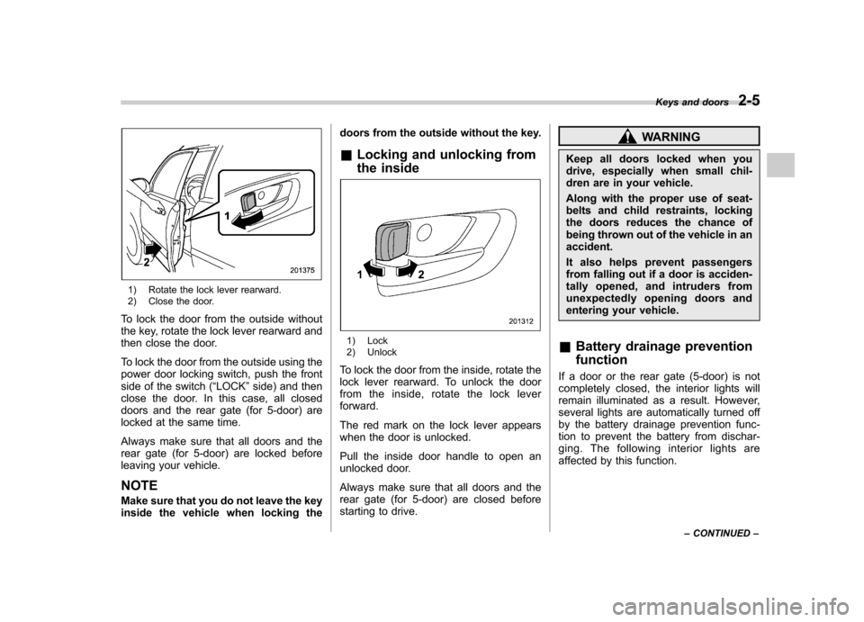
1) Rotate the lock lever rearward.
2) Close the door.
To lock the door from the outside without
the key, rotate the lock lever rearward and
then close the door.
To lock the door from the outside using the
power door locking switch, push the front
side of the switch ( “LOCK ”side) and then
close the door. In this case, all closed
doors and the rear gate (for 5-door) are
locked at the same time.
Always make sure that all doors and the
rear gate (for 5-door) are locked before
leaving your vehicle. NOTE
Make sure that you do not leave the key
inside the vehicle when locking the doors from the outside without the key.
& Locking and unlocking from
the inside
1) Lock
2) Unlock
To lock the door from the inside, rotate the
lock lever rearward. To unlock the door
from the inside, rotate the lock leverforward.
The red mark on the lock lever appears
when the door is unlocked.
Pull the inside door handle to open an
unlocked door.
Always make sure that all doors and the
rear gate (for 5-door) are closed before
starting to drive.
WARNING
Keep all doors locked when you
drive, especially when small chil-
dren are in your vehicle.
Along with the proper use of seat-
belts and child restraints, locking
the doors reduces the chance of
being thrown out of the vehicle in anaccident.
It also helps prevent passengers
from falling out if a door is acciden-
tally opened, and intruders from
unexpectedly opening doors and
entering your vehicle.
& Battery drainage prevention function
If a door or the rear gate (5-door) is not
completely closed, the interior lights will
remain illuminated as a result. However,
several lights are automatically turned off
by the battery drainage prevention func-
tion to prevent the battery from dischar-
ging. The following interior lights are
affected by this function. Keys and doors
2-5
– CONTINUED –
Page 95 of 458

2-6Keys and doors
Item Switch
position Automatically turning
off
Map lights
*1OFF*1Approximately 30 seconds later
Dome light DOOR Approximately 20
minutes later
Ignition
switch light —Approximately 20
minutes later
Door steplights —
None
*2
Cargo arealightDOOR
None*2
*1: The battery drainage prevention function
affects only the map lights on models with the
moonroof, and only when the map light
switches are in the OFF position. The map
lights on models without the moonroof do not
turn off automatically, so push the light switches
manually to turn them off.
*2: The door step lights and the cargo area light
are not affected by the battery drainage
prevention function, so the lights do not turn
off automatically. To turn off the lights, it is
necessary that each door and the rear gate (5-
door) are completely closed.
The operational/non-operational setting of
this function can be changed by a
SUBARU dealer. Contact your SUBARU
dealer to change the setting. NOTE .
The factory setting (default setting)
for this function is set as “operational ”.
. When leaving the vehicle, please
make sure that all doors and the rear
gate (5-door) are completely closed.. The battery drainage prevention
function does not operate while the
key is in the ignition switch. Power door locking switches
Type A
Type B
1) Lock
2) Unlock
Page 97 of 458

2-8Keys and doors
Remote keyless entry system
CAUTION
. Do not expose the remote trans-
mitter to severe shocks, such as
those experienced as a result of
dropping or throwing.
. Do not take the remote transmit-
ter apart except when replacing
the battery.
. Do not get the remote transmitter
wet. If it gets wet, wipe it dry with
a cloth immediately.
. When you carry the remote trans-
mitter on an airplane, do not
press the button of the remote
transmitter while in the airplane.
When any button of the remote
transmitter is pressed, radio
waves are sent and may affect
the operation of the airplane.
When you carry the remote trans-
mitter in a bag on an airplane,
take measures to prevent the
buttons of the remote transmitter
from being pressed.
. FCC WARNING
Changes or modifications not
expressly approved by the party responsible for compliance
could void the user
’s authority
to operate the equipment.
This device complies with Part 15 of
the FCC Rules and RSS-Gen of IC
Rules. Operation is subject to the
following two conditions: (1) this de-
vice may not cause harmful interfer-
ence, and (2) this device must accept
any interference received, including
interference that may cause undesiredoperation.
Two transmitters are provided for your vehicle.
The remote keyless entry system has the
following functions. . Locking and unlocking the doors (and
rear gate on the 5-door) without a key. Unlocking the rear gate on the 5-door
without a key. Opening the trunk lid on the 4-door
without a key. Sounding a panic alarm
. Arming and disarming the alarm sys-
tem. For detailed information, refer to “ Alarm system ”F 2-16.
The operable distance of the remote
keyless entry system is approximately 30
feet (10 meters). However, this distance will vary depending on environmental
conditions. The system
’s operable dis-
tance will be shorter in areas near a
facility or electronic equipment emitting
strong radio waves such as a power plant,
broadcast station, TV tower, or remote
controller of home electronic appliances.
The remote keyless entry system does not
operate when the key is inserted in the
ignition switch.
: Trunk lid/rear gate unlock button: Unlock/disarm button: Lock/arm button
A: Panic button
1) Front
2) Back
Page 100 of 458
&Selecting audible signal op- eration
Using an electronic chirp, the system will
give you an audible signal when the doors
lock and unlock. If desired, you may turn
the audible signal off.
Do the following to deactivate the audible
signal. You can also use the same steps
to restore the function.
1. Sit in the driver ’s seat and shut all
doors and the rear gate.
2. Hold down the REAR (UNLOCK) side
of the power door locking switch.
3. While holding down the REAR (UN-
LOCK) side of the power door locking
switch, pull the key out and re-insert it into
the ignition switch at least 6 times within
10 seconds after Step 2.
4. Open and close the driver ’s door once
within 10 seconds after Step 3.
5. The turn signal lights flash 3 times to
indicate completion of the setting.
You may have the above settings done by
your SUBARU dealer. Also, for models
with the genuine SUBARU navigation
system, the setting can be changed using
the navigation monitor. For details, please
refer to the Owner ’s Manual supplement
for the navigation system. &
Replacing the battery
CAUTION
. Do not let dust, oil or water get on
or in the transmitter when repla-
cing the battery.
. Be careful not to damage the
printed circuit board in the trans-
mitter when replacing the battery.
. Be careful not to allow children to
touch the battery and any re-
moved parts; children could
swallow them.
. There is a danger of explosion if
an incorrect replacement battery
is used. Replace only with the
same or equivalent type of bat-
tery.
. Batteries should not be exposed
to excessive heat such as sun-
shine, fire or the like.
When the transmitter battery begins to get
weak, transmitter range will begin to
decrease. Replace the battery as soon
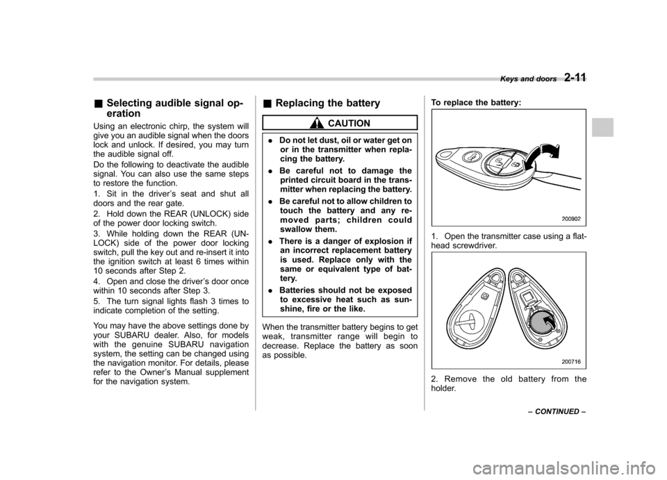
as possible. To replace the battery:
1. Open the transmitter case using a flat-
head screwdriver.
2. Remove the old battery from the
holder.Keys and doors
2-11
– CONTINUED –
Page 101 of 458
2-12Keys and doors
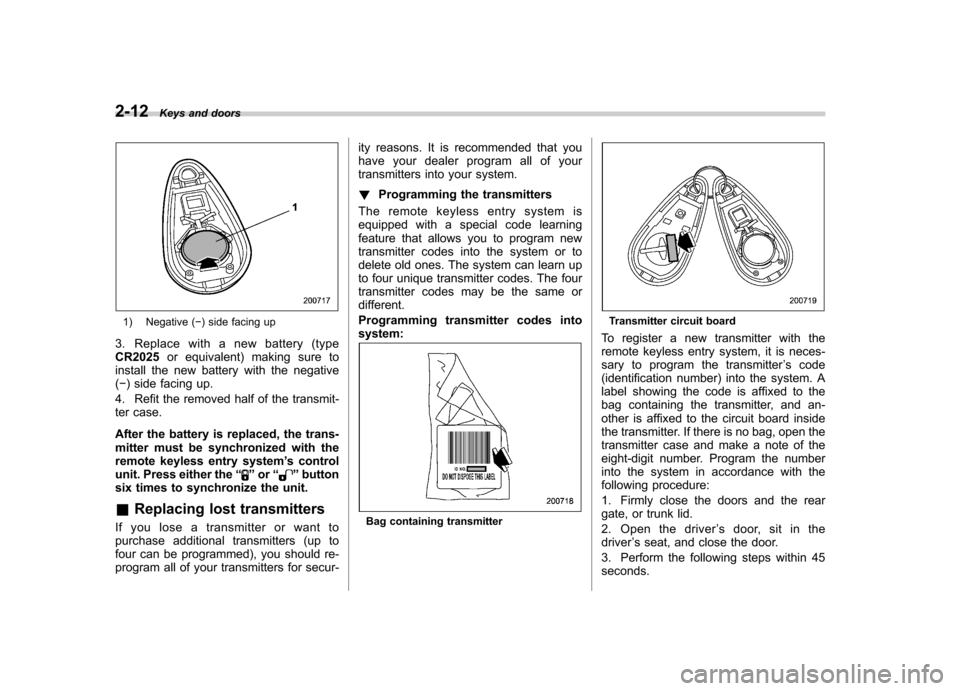
1) Negative ( �) side facing up
3. Replace with a new battery (type CR2025 or equivalent) making sure to
install the new battery with the negative( � ) side facing up.
4. Refit the removed half of the transmit-
ter case.
After the battery is replaced, the trans-
mitter must be synchronized with the
remote keyless entry system ’s control
unit. Press either the “
”or “”button
six times to synchronize the unit. & Replacing lost transmitters
If you lose a transmitter or want to
purchase additional transmitters (up to
four can be programmed), you should re-
program all of your transmitters for secur- ity reasons. It is recommended that you
have your dealer program all of your
transmitters into your system. !
Programming the transmitters
The remote keyless entry system is
equipped with a special code learning
feature that allows you to program new
transmitter codes into the system or to
delete old ones. The system can learn up
to four unique transmitter codes. The four
transmitter codes may be the same or
different.
Programming transmitter codes into system:
Bag containing transmitter
Transmitter circuit board
To register a new transmitter with the
remote keyless entry system, it is neces-
sary to program the transmitter ’s code
(identification number) into the system. A
label showing the code is affixed to the
bag containing the transmitter, and an-
other is affixed to the circuit board inside
the transmitter. If there is no bag, open the
transmitter case and make a note of the
eight-digit number. Program the number
into the system in accordance with the
following procedure:
1. Firmly close the doors and the rear
gate, or trunk lid.
2. Open the driver ’s door, sit in the
driver ’s seat, and close the door.
3. Perform the following steps within 45 seconds.
Page 108 of 458
&Disarming the system
Briefly press the “
”button (for less than
2 seconds) on the remote transmitter. The
driver ’s door will unlock, an electronic
chirp will sound twice, the turn signal
lights will flash twice. The flashing of the
security indicator light will then change
slowly (once approximately every 3 sec-
onds from twice approximately every 2
seconds), indicating that the alarm system
has been disarmed. NOTE
After disarming the alarm system,
briefly press the “
”button a second
time within 5 seconds to unlock all
other doors and the rear gate (5-door). ! Emergency disarming
If you cannot disarm the system using the
transmitter (i.e. the transmitter is lost,
broken or the transmitter battery is too
weak), you can disarm the system without
using the transmitter as follows. . Turn the ignition switch from the
“ LOCK ”to the “ON ”position with a
registered key. & Valet mode
When you choose the valet mode, the
alarm system does not operate. In valet
mode, the remote transmitter is used only for locking and unlocking the doors and
rear gate (5-door) and panic activation.
To enter the valet mode, change the
setting of your vehicle
’s alarm system for
deactivation mode. Refer to “Activating
and deactivating the alarm system ”F 2-
16. The security indicator light will con-
tinue to flash once every 3 seconds
indicating that the system is in the valetmode.
To exit valet mode, change the setting of
your vehicle ’s alarm system for activation
mode. Refer to “Activating and deactivat-
ing the alarm system ”F 2-16.
& Passive arming
When passive arming mode has been
programmed by the dealer, arming of the
system is automatically accomplished
without using the remote transmitter. Note
that in this mode, DOORS MUST BE
MANUALLY LOCKED. ! To enter the passive mode
If you wish to program the passive arming
mode, have it done by your SUBARU
dealer. !
Arming the system
CAUTION
In passive mode, the system will
automatically activate the alarm but
WILL NOT automatically lock the
doors. In order to lock the doors
you must either lock them as in-
dicated in step 4 below or with the
key once they have been closed.
Failure to lock the doors manually
will result in a higher security risk.
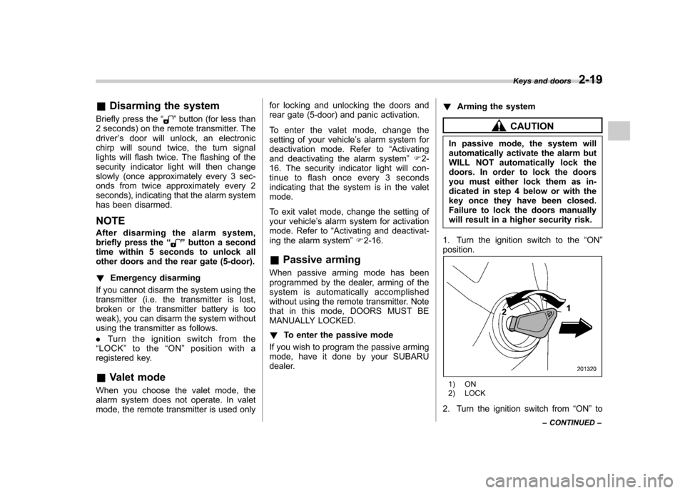
1. Turn the ignition switch to the “ON ”
position.
1) ON
2) LOCK
2. Turn the ignition switch from “ON ”to
Keys and doors
2-19
– CONTINUED –