brake fluid SUBARU IMPREZA 2016 5.G Owners Manual
[x] Cancel search | Manufacturer: SUBARU, Model Year: 2016, Model line: IMPREZA, Model: SUBARU IMPREZA 2016 5.GPages: 594, PDF Size: 5.36 MB
Page 8 of 594

&Abbreviation list
You may find several abbreviations in this
manual. The meanings of the abbrevia-
tions are shown in the following list.
Abbreviation Meaning
A/C Air conditioner
ALR/ELR Automatic locking retractor/
Emergency locking retractor
ABS Anti-lock brake system
AKI Anti knock index
ALR Automatic locking retractor
AWD All-wheel drive
BSD/RCTA Blind Spot Detection/Rear
Cross Traffic Alert
CVT Continuously variable trans-
mission
DRL Daytime running light
EBD Electronic brake force distri-
bution
ELR Emergency locking retractor
GAW Gross axle weight
GAWR Gross axle weight rating
GPS Global positioning system
GVW Gross vehicle weight
GVWR Gross vehicle weight rating
HID High intensity discharge Abbreviation
Meaning
INT Intermittent
LATCH Lower anchors and tethers for
children
LED Light emitting diode
MIL Malfunction indicator light
MMT Methylcyclopentadienyl man-
ganese tricarbonyl
MT Manual transmission
OBD On-board diagnostics
RON Research octane number
SRF Steering responsive fog lights
system
SRS Supplemental restraint sys-
tem
TIN Tire identification number
TPMS Tire pressure monitoring sys-
tem
Vehicle symbols
There are some of the symbols you may
see on your vehicle.
For warning and indicator lights, refer to
“
Warning and indicator lights ”F 22.
Mark Name
WARNING
CAUTION
Read these instructions care-
fully
Wear eye protection
Battery fluid contains sulfuric
acid
Keep children away
Keep flames away
Prevent explosions
3
Page 13 of 594
General information
&California proposition 65
warning
WARNING
Engine exhaust, some of its consti-
tuents, and certain vehicle compo-
nents contain or emit chemicals
known to the State of California to
cause cancer and birth defects or
other reproductive harm. In addi-
tion, certain fluids in vehicles and
certain components of product wear
contain or emit chemicals known to
the State of California to cause
cancer and birth defects or other
reproductive harm.
&California Perchlorate Advi-
sory
Certain vehicle components such as air-
bag modules, seatbelt pretensioners and
keyless entry transmitter batteries may
contain perchlorate material. Special
handling may apply for service or vehicle
end of life disposal. See www.dtsc.ca.gov/
hazardouswaste/perchlorate.
&Noise from under the vehicle
NOTE
You may hear a noise from under the
vehicle approximately 5 to 10 hours
after the ignition switch is turned to the
“LOCK ”/“OFF ”position. However, this
does not indicate a malfunction. This
noise is caused by the operation of the
fuel evaporation leakage checking sys-
tem and the operation is normal. The
noise will stop after approximately 15
minutes.
& Event data recorder
This vehicle is equipped with an event
data recorder (EDR). The main purpose of
an EDR is to record, in certain crash or
near crash-like situations, such as an air
bag deployment or hitting a road obstacle,
data that will assist in understanding how
a vehicle’ s systems performed. The EDR
is designed to record data related to
vehicle dynamics and safety systems for
a short period of time, typically 30 seconds
or less. The EDR in this vehicle is
designed to record such data as:
. How various systems in your vehicle
were operating;
. Whether or not the driver and passen-
ger safety belts were buckled/fastened;
. How far (if at all) the driver was depressing the accelerator and/or brake
pedal; and,
.
How fast the vehicle was traveling.
These data can help provide a better
understanding of the circumstances in
which crashes and injuries occur. NOTE:
EDR data are recorded by your vehicle
only if a non-trivial crash situation occurs;
no data are recorded by the EDR under
normal driving conditions and no personal
data (e.g., name, gender, age, and crash
location) are recorded. However, other
parties, such as law enforcement, could
combine the EDR data with the type of
personally identifying data routinely ac-
quired during a crash investigation.
To read data recorded by an EDR, special
equipment is required, and access to the
vehicle or the EDR is needed. In addition
to the vehicle manufacturer, other parties,
such as law enforcement, that have the
special equipment, can read the informa-
tion if they have access to the vehicle or
the EDR.
8
Page 27 of 594

&Warning and indicator lights
Mark Name Page
Seatbelt warning light 3-14
Front passenger’s
seatbelt warning light 3-14
SRS airbag system
warning light3-15
/Front passenger
’s
frontal airbag ON indi-
cator 3-16
/Front passenger
’s
frontal airbag OFF in-
dicator 3-16
CHECK ENGINE
warning light/Malfunc-
tion indicator light3-16
Coolant temperature
low indicator light/
Coolant temperature
high warning light3-17
Charge warning light 3-18
Oil pressure warning
light
3-18
Engine oil level warn-
ing light3-18Mark Name Page
AT OIL TEMP warning
light (CVT models)
3-19
ABS warning light 3-21
Brake system warning
light
3-21
Door open warning
light3-23
AWD warning light
(CVT models)
3-23
Power steering warn-
ing light3-23
Hill start assist warn-
ing light/Hill start assist
OFF indicator light3-22
Vehicle Dynamics
Control warning light/
Vehicle Dynamics
Control operation indi-
cator light3-24
Vehicle Dynamics
Control OFF indicator
light
3-25
Turn signal indicator
lights
3-31Mark Name Page
High beam indicator
light
3-31
Automatic headlight
beam leveler warning
light (if equipped)3-31
Front fog light indicator
light (if equipped)
3-31
Access key warning
indicator (if equipped)3-25
Security indicator light 3-30
Headlight indicator
light (if equipped)
3-32
Cruise control indica-
tor light (if equipped)3-31
Cruise control set in-
dicator light (if
equipped)3-31
Low fuel warning light 3-22
Low tire pressure
warning light
(U.S.-spec. models)3-19
Windshield washer
fluid warning light
3-19
22
Page 146 of 594

Ignition switch (models without“keyless
access with push-button start system ”)......... 3-4
LOCK .................................................................. 3-4
ACC.................................................................... 3-5
ON...................................................................... 3-5
START ................................................................ 3-5
Key reminder chime ............................................ 3-5
Ignition switch light (if equipped) ......................... 3-6
Push-button ignition switch (models with
push-button start system) ............................... 3-6
Safety precautions.............................................. 3-6
Operating range for push-button start system ...... 3-6
Switching power ................................................. 3-7
When access key does not operate properly ........ 3-8
Hazard warning flasher....................................... 3-8
Meters and gauges. ............................................. 3-9
Combination meter illumination ........................... 3-9
Canceling the function for meter/gauge needle movement upon turning on the ignition
switch ............................................................... 3-9
Speedometer ...................................................... 3-10
Odometer ........................................................... 3-10
Double trip meter ............................................... 3-11
Tachometer ........................................................ 3-11
Fuel gauge ......................................................... 3-12
ECO gauge (if equipped) .................................... 3-12
Warning and indicator lights ............................. 3-13Initial illumination for system check .................... 3-13
Seatbelt warning light and chime ........................ 3-14
SRS airbag system warning light ........................ 3-15Front passenger
’s frontal airbag ON and OFF
indicators ........................................................ 3-16
CHECK ENGINE warning light/Malfunction indicator light .................................................. 3-16
Coolant temperature low indicator light/Coolant temperature high warning light ......................... 3-17
Charge warning light .......................................... 3-18
Oil pressure warning light .................................. 3-18
Engine low oil level warning light ....................... 3-18
Windshield washer fluid warning light ................ 3-19
AT OIL TEMP warning light (CVT models) ........... 3-19
Low tire pressure warning light (U.S.-spec. models) ........................................................... 3-19
ABS warning light .............................................. 3-21
Brake system warning light (red) ........................ 3-21
Low fuel warning light ....................................... 3-22
Hill start assist warning light/Hill start assist OFF indicator light .................................................. 3-22
Door open warning light .................................... 3-23
All-Wheel Drive warning light (CVT models) ... ..... 3-23
Power steering warning light .............................. 3-23
Vehicle Dynamics Control warning light/Vehicle Dynamics Control operation indicator light .. ..... 3-24
Vehicle Dynamics Control OFF indicator light ..... 3-25
Warning chimes and warning indicator of the keyless access with push-button start system (if
equipped) ........................................................ 3-25
Security indicator light ....................................... 3-30
Select lever/gear position indicator (CVT models) ........................................................... 3-30
Turn signal indicator lights ................................. 3-31
High beam indicator light ................................... 3-31
Instruments and controls
3
Page 158 of 594
efficiency.
NOTE
.The ECO gauge shows only an
approximate indication of fuel effi-
ciency.
. After resetting the trip meter, the
average rate of fuel consumption is not
shown until driving 0.6 mile (1 km).
Before that time, the ECO gauge does
not operate.
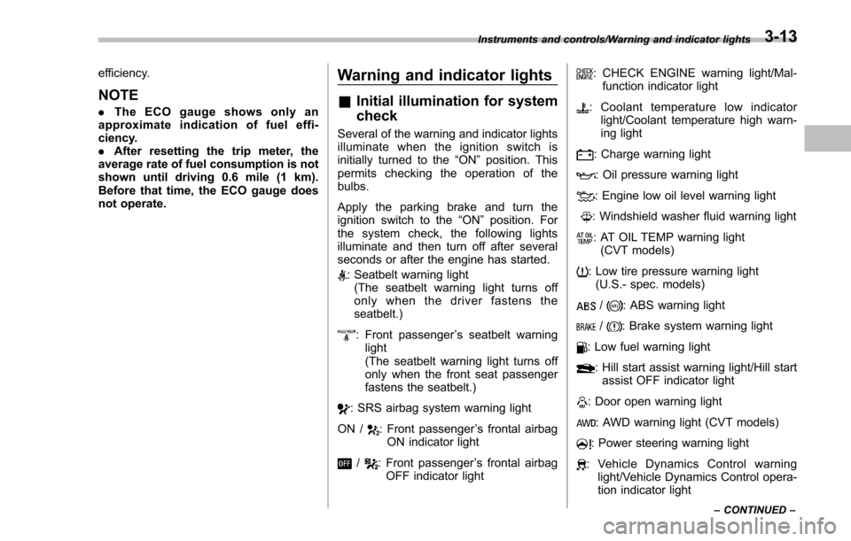
Warning and indicator lights
& Initial illumination for system
check
Several of the warning and indicator lights
illuminate when the ignition switch is
initially turned to the “ON ”position. This
permits checking the operation of the
bulbs.
Apply the parking brake and turn the
ignition switch to the “ON”position. For
the system check, the following lights
illuminate and then turn off after several
seconds or after the engine has started.
: Seatbelt warning light (The seatbelt warning light turns off
only when the driver fastens the
seatbelt.)
: Front passenger ’s seatbelt warning
light
(The seatbelt warning light turns off
only when the front seat passenger
fastens the seatbelt.)
: SRS airbag system warning light
ON /
: Front passenger ’s frontal airbag
ON indicator light
/: Front passenger ’s frontal airbag
OFF indicator light
: CHECK ENGINE warning light/Mal- function indicator light
: Coolant temperature low indicator light/Coolant temperature high warn-
ing light
: Charge warning light
: Oil pressure warning light
: Engine low oil level warning light
: Windshield washer fluid warning light
: AT OIL TEMP warning light(CVT models)
: Low tire pressure warning light(U.S.- spec. models)
/: ABS warning light
/: Brake system warning light
: Low fuel warning light
: Hill start assist warning light/Hill startassist OFF indicator light
: Door open warning light
: AWD warning light (CVT models)
: Power steering warning light
: Vehicle Dynamics Control warning light/Vehicle Dynamics Control opera-
tion indicator light
Instruments and controls/Warning and indicator lights
–CONTINUED –3-13
Page 166 of 594
&ABS warning light
CAUTION
.If any of the following conditions
occur, we recommend that you
have the ABS repaired at the first
available opportunity by your
SUBARU dealer.
– The warning light does not
illuminate when the ignition
switch is turned to the “ON”
position.
– The warning light illuminates
when the ignition switch is
turned to the “ON”position,
but it does not turn off even
when the vehicle speed ex-
ceeds approximately 25 mph
(40 km/h).
– The warning light illuminates
during driving.
. When the warning light is on (and
the brake system warning light is
off), the ABS function shuts
down. However, the conventional
brake system continues to oper-
ate normally.
The ABS warning light illuminates to-
gether with the brake system warning light if the EBD system malfunctions. For
further details of the EBD system mal-
function warning, refer to
“Electronic
Brake Force Distribution (EBD) system
warning ”F 3-22.
NOTE
If the warning light behavior is as
described in the following conditions,
the ABS may be considered normal.
. The warning light illuminates when
the ignition switch is turned to the
“ON ”position and turns off approxi-
mately 2 seconds after the engine has
started.
. The warning light illuminates right
after the engine is started but turns off
immediately, remaining off.
. The warning light remains illumi-
nated after the engine has been started,
but it turns off when the vehicle speed
reaches approximately 25 mph (40
km/h).
. The warning light illuminates during
driving, but it turns off immediately and
remains off.
When driving with an insufficient battery
voltage such as when the engine is jump
started, the ABS warning light may illumi-
nate. This is due to the low battery voltage
and does not indicate a malfunction.
When the battery becomes fully charged, the light will turn off.
&Brake system
warning light (red)
The light illuminates with the parking
brake applied while the ignition switch is
in the
“ON”position. It turns off when the
parking brake is fully released.
WARNING
. Driving with the brake system
warning light on is dangerous.
This indicates your brake system
may not be working properly. If
the light remains illuminated,
have the brakes inspected by a
SUBARU dealer immediately.
. If at all in doubt about whether
the brakes are operating prop-
erly, do not drive the vehicle.
Have your vehicle towed to the
nearest SUBARU dealer for re-
pair.
The brake system warning light has the
following functions.
! Brake fluid level warning
This light illuminates when the brake fluid
level has dropped to near the “MIN”level
of the brake fluid reservoir with the ignition
Instruments and controls/Warning and indicator lights
–CONTINUED –3-21
Page 167 of 594
Instruments and controls/Warning and indicator lights
switch in the“ON”position and with the
parking brake fully released.
If the brake system warning light should
illuminate while driving (with the parking
brake fully released and with the ignition
switch positioned in “ON”), it could be an
indication of leaking of brake fluid or worn
brake pads. If this occurs, immediately
stop the vehicle at the nearest safe
location and check the brake fluid level.
If the fluid level is below the “MIN”mark in
the reservoir, do not drive the vehicle.
Have the vehicle towed to the nearest
SUBARU dealer for repair.
! Electronic Brake Force Distribution
(EBD) system warning
The brake system warning light also
illuminates if a malfunction occurs in the
EBD system. In that event, it illuminates
together with the ABS warning light.
The EBD system may be malfunctioning if
the brake system warning light and ABS
warning light illuminate simultaneously
during driving.
Even if the EBD system fails, the conven-
tional braking system will still function.
However, the rear wheels will be more
prone to locking when the brakes are
applied harder than usual and the vehi-
cle ’s motion may therefore become some-
what harder to control. If the brake system warning light and ABS
warning light illuminate simultaneously,
take the following steps.
1. Stop the vehicle in the nearest safe,
flat location.
2. Shut down the engine, apply the
parking brake and then restart it.
3. Release the parking brake. Even if
both warning lights turn off, the EBD
system may be malfunctioning. Drive
carefully to the nearest SUBARU dealer
and have the system inspected.
4. If both warning lights illuminate again
and remain illuminated after the engine
has been restarted, shut down the engine
again, apply the parking brake, and check
the brake fluid level.
5. If the brake fluid level is not below the
“
MIN ”mark, the EBD system may be
malfunctioning. Drive carefully to the
nearest SUBARU dealer and have the
system inspected.
6. If the brake fluid level is below the
“ MIN ”mark, DO NOT drive the vehicle.
Instead, have the vehicle towed to the
nearest SUBARU dealer for repair.
&Low fuel warning light
The low fuel warning light illuminates
when the tank is nearly empty, at approxi-
mately 2.6 US gal (10.0 liters, 2.2 Imp gal). It only operates when the ignition switch is
in the
“ON”position.
CAUTION
Promptly put fuel in the tank when-
ever the low fuel warning light
illuminates. Engine misfires as a
result of an empty tank could cause
damage to the engine.
NOTE
This light does not turn off unless the
tank is replenished up to an internal
fuel quantity of approximately 4.5 US
gal (17 liters, 3.7 Imp gal).
&Hill start assist warning
light/Hill start assist
OFF indicator light
! Hill start assist warning light
While the engine is running, if there are
any malfunctions in the Hill start assist
system, the warning light will illuminate.
WARNING
When the Hill start assist warning
light illuminates, have the vehicle
inspected at an authorized SUBARU
3-22
Page 394 of 594
CAUTION
Trapping small animals in the cool-
ing fan and belts of the engine may
result in a malfunction. Check that
no small animal enters the engine
compartment and under the vehicle
before starting the engine.
NOTE
Engine oil, engine coolant, brake fluid,
washer fluid and other fluid levels
should be checked daily, weekly or at
fuel stops.
Starting and stopping the
engine (models without
push-button start system)
CAUTION
Do not operate the starter motor
continuously for more than 10 sec-
onds. If the engine fails to start after
operating the starter for 5 to 10
seconds, wait for 10 seconds or
more before trying again.
NOTE
It may be difficult to start the engine
when the battery has been discon-
nected and reconnected (for mainte-
nance or other purposes). This diffi-
culty is caused by the electronically
controlled throttle’s self-diagnosis
function. To overcome it, keep the
ignition switch in the “ON”position
for approximately 10 seconds before
starting the engine.
& Starting engine
! General precautions when starting
engine
WARNING
.Never start the engine from out-
side the vehicle (except when
using the remote engine start
system). It may result in an
accident.
. Do not leave the engine running
in locations with poor ventilation,
such as a garage and indoors.
The exhaust gas may enter the
vehicle or indoors, and it may
result in carbon monoxide poi-
soning.
. Do not start the engine near dry
foliage, paper, or other flam-
mable substances. The exhaust
pipe and exhaust emissions can
create a fire hazard at high
temperatures.
CAUTION
. If the engine is stopped during
driving, the catalyst may over-
heat and burn.
Starting and operating/Starting and stopping the engine (models without push –button start system)
–CONTINUED –7-9
Page 408 of 594
mph (km/h)
Gear Except
Crosstrek models Crosstrek models
1st 30 (48) 28 (46)
2nd 55 (89) 53 (86)
3rd 80 (130) 78 (126)
4th Legal speed limit
(Posted limit speed)
5th
WARNING
When shifting down a gear, ensure
that the vehicle is not travelling at a
speed exceeding the Maximum Al-
lowable Speed for the gear which is
about to be selected. Failure to
observe this precaution can lead to
engine over-revving and this in turn
can result in engine damage.
In addition, sudden application of
engine brakes when the vehicle is
travelling on a slippery surface can
lead to wheel locking; as a conse-
quence, control of the vehicle may
be lost and the risk of an accident
increased.
NOTE
Never exceed the posted speed limit.
& Driving tips
Do not drive with your foot resting on the
clutch pedal and do not use the clutch to
hold your vehicle at a standstill on an
upgrade. Either of those actions may
cause clutch damage.
Do not drive with your hand resting on the
shift lever. This may cause wear on the
transmission components.
When it is necessary to reduce vehicle
speed due to slow traffic, turning corners,
or driving up steep hills, downshift to a
lower gear before the engine starts to
labor.
On steep downgrades, downshift the
transmission to 4th, 3rd or 2nd gear as
necessary; this helps to maintain a safe
speed and to extend brake pad life.
In this way, the engine provides a braking
effect. Remember, if you “ride”(over use)
the brakes while descending a hill, they
may overheat and not work properly.
The engine may, on rare occasions, knock
when the vehicle rapidly accelerates or
rapidly pulls away from a standstill. This
phenomenon is not an indication of a
problem in your vehicle.
Continuously variable trans-
mission
WARNING
Do not shift from the “P”or “N”
position into the “D”or “R”position
while depressing the accelerator
pedal. This may cause the vehicle
to jump forward or backward.
CAUTION
. Shift into the “P ” or “R”position
only after the vehicle is comple-
tely stopped. Shifting while the
vehicle is moving may cause
damage to the transmission.
. Do not race the engine for more
than 5 seconds in any position
except the “N”or “P ” position
when the brake is applied or
when chocks are used in the
wheels. This may cause the
transmission fluid to overheat.
. Do not shift from the “D”position
into the “R ” position or vice
versa until the vehicle has com-
pletely stopped. Such shifting
may cause damage to the trans-
Starting and operating/Continuously variable transmission
–CONTINUED –7-23
Page 409 of 594
Starting and operating/Continuously variable transmission
mission.
. When parking the vehicle, first
securely apply the parking brake
and then place the select lever in
the “P”position. Do not park for
a long time with the select lever
in any other position as doing so
could result in a dead battery.
& Continuously variable trans-
mission features
The continuously variable transmission is
electronically controlled and provides an
infinite number of forward speeds and 1
reverse speed. For some models, it also
has a manual mode or an “L”position.
NOTE
. When the engine coolant tempera-
ture is still low, the transmission will
upshift or downshift at higher engine
speeds than when the coolant tempera-
ture is sufficiently high in order to
shorten the warm-up time and improve
driveability. The gearshift timing will
automatically shift to the normal timing
after the engine has warmed up.
. Immediately after transmission fluid
is replaced, you may feel that the
transmission operation is somewhat
unusual. This results from invalidation of data which the on-board computer
has collected and stored in memory to
allow the transmission to shift at the
most appropriate times for the current
condition of your vehicle. Optimized
shifting will be restored as the vehicle
continues to be driven for a while.
.
When driving a CVT model under
continuous heavy load conditions such
as when towing a camper or climbing a
long, steep hill, the engine speed or the
vehicle speed may automatically be
reduced. This is not a malfunction. This
phenomenon results from the engine
control function maintaining the cool-
ing performance of the vehicle. The
engine and vehicle speed will return to
a normal speed when the engine is able
to maintain the optimum cooling per-
formance after the heavy load de-
creases. Driving under a heavy load
must be performed with extreme care.
Do not try to pass a vehicle in front
when driving on an uphill slope while
towing. .
The continuously variable transmis-
sion is a chain type system that
provides superior transmission effi-
ciency for maximum fuel economy. At
times, depending on varying driving
conditions, a chain operating sound
may be heard that is characteristic of
this type of system.
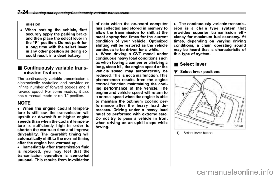
& Select lever
! Select lever positions
1) Select lever button
7-24