SUBARU IMPREZA WRX 2007 3.G Manual Online
Manufacturer: SUBARU, Model Year: 2007, Model line: IMPREZA WRX, Model: SUBARU IMPREZA WRX 2007 3.GPages: 364, PDF Size: 11.91 MB
Page 81 of 364
1-56Seat, seatbelt and SRS airbags
ger’s side)
. Side airbag sensor (Center pillar right-
hand side) . Side airbag sensor (Center pillar left-
hand side). Side airbag module (Driver ’s side)
. Side airbag module (Front passenger ’s
side). Seatbelt pretensioner (Driver ’s side)
. Seatbelt pretensioner (Front passen-
ger ’s side)
. Seatbelt buckle switch (Driver ’s side)
. Seatbelt buckle switch (Front passen-
ger ’s side)
. Driver ’s seat position sensor
. Front passenger ’s seatbelt tension
sensor. Front passenger ’s occupant detection
system weight sensor. Front passenger ’s occupant detection
control module. Front passenger ’s frontal airbag ON
and OFF indicator. All related wiring
WARNING
If the warning light exhibits any of
the following conditions, there may
be a malfunction in the seatbelt
pretensioners and/or SRS airbag system. Immediately take your vehi-
cle to your nearest SUBARU dealer
to have the system checked. Unless
checked and properly repaired, the
seatbelt pretensioners and/or SRS
airbag will not operate properly in
the event of a collision, which may
increase the risk of injury. .
Flashing or flickering of the warn-
ing light
. No illumination of the warning
light when the ignition switch is
first turned to the “ON ”position
. Continuous illumination of the
warning light
. Illumination of the warning light
while driving
& SRS airbag system servicing
WARNING
. When discarding an airbag mod-
ule or scrapping the entire vehi-
cle damaged by a collision, con-
sult your SUBARU dealer.
. The SRS airbag has no user-
serviceable parts. Do not use
electrical test equipment on any
circuit related to the SRS airbag system. For required servicing of
the SRS airbag, see your nearest
SUBARU dealer. Tampering with
or disconnecting the system
’s
wiring could result in accidental
inflation of the SRS airbag or
could make the system inopera-
tive, which may result in serious
injury. The wiring harnesses of
the SRS airbag system are cov-
ered with yellow insulation and
system connectors are yellow for
easy identification.
CAUTION
If you need service or repair in areas
listed in the following, have an
authorized SUBARU dealer perform
the work. The SRS airbag control
module, impact sensors and airbag
modules are stored in these areas. . Under the center console
. Inside each front fender
. Steering wheel and column and
nearby areas
. Top of the dashboard on front
passenger ’s side and nearby
areas
. Each front seat and nearby area
Page 82 of 364
.Inside each center pillar
In the event that the SRS airbag is
deployed, replacement of the system
should be performed only by an author-
ized SUBARU dealer. When the compo-
nents of the SRS airbag system are
replaced, use only genuine SUBARUparts.
To ensure their long-term reliability, the
SRS airbags must be inspected by a
SUBARU dealer ten years after the date
of manufacture, which is shown on the
certification plate attached to the driver ’s
doorjamb. NOTE
In the following cases, contact your
SUBARU dealer as soon as possible. . The front part of the vehicle was
involved in an accident in which only
the driver ’s SRS frontal airbag or both
driver ’s and front passenger ’sSRS
frontal airbags did not deploy.. The pad section of the steering
wheel or front passenger ’s frontal air-
bag cover is scratched, cracked, or
otherwise damaged.
In addition, if your vehicle is equipped
with SRS side airbags, contact your
SUBARU dealer as soon as possible in the following cases. .
Either center pillar or a nearby area
of the vehicle was involved in an
accident in which the SRS side airbag
did not deploy.. The fabric or leather of either front
seatback is cut, frayed, or otherwisedamaged.
& Precautions against vehicle modification
WARNING
. To avoid accidental activation of
the system or rendering the sys-
tem inoperative, which may re-
sult in serious injury, no modifi-
cations should be made to any
components or wiring of the SRS
airbag system.
This includes following modifica- tions: . Installation of custom steering
wheels
. Attachment of additional trim
materials to the dashboard
. Installation of custom seats
. Replacement of seat fabric or
leather .
Installation of additional fabric
or leather on the front seat
. Installation of additional elec-
trical/electronic equipment
such as a mobile two-way
radioonorneartheSRS
airbag system components
and/or wiring is not advisable.
This could interfere with prop-
er operation of the SRS airbagsystem.CAUTION
Do not perform any of the following
modifications. Such modifications
can interfere with proper operation
of the SRS airbag system. . Attachment of any equipment
(bush bar, winches, snow plow,
skid plate, etc.) other than genu-
ine SUBARU accessory parts to
the front end.
. Modification of the suspension
system or front end structure.
. Installation of a tire of different
size and construction from the
tires specified on the vehicle
placard attached to the driver ’s
door pillar or specified for indivi-
dual vehicle models in this Own-
Seat, seatbelt and SRS airbags
1-57
– CONTINUED –
Page 83 of 364

1-58Seat, seatbelt and SRS airbags
er’s Manual.
. Attachment of any equipment
(side steps or side sill protectors,
etc.) other than genuine SUBARU
accessory parts to the side body.
Always consult your SUBARU dealer if
you want to install any accessory parts on
your vehicle.
Page 84 of 364

Keys..................................................................... 2-2
Key number plate ................................................ 2-2
Immobilizer (Turbo models) ................................ 2-3
Security ID plate .................................................. 2-3
Security indicator light ........................................ 2-4
Key replacement ................................................. 2-4
Door locks ........................................................... 2-4
Locking and unlocking from the outside .. ............ 2-4
Locking and unlocking from the inside ................ 2-5
Key lock-in prevention function ........................... 2-5
Power door locking switches ............................. 2-6
Remote keyless entry system ............................ 2-7
Locking the doors ............................................... 2-7
Unlocking the doors ............................................ 2-8
Illuminated entry ................................................. 2-8
Vehicle finder function ......................................... 2-8
Sounding a panic alarm ....................................... 2-8
Selecting audible signal operation ....................... 2-8
Replacing the battery .......................................... 2-9
Replacing lost transmitters ................................. 2-10
Alarm system ..................................................... 2-13
System operation ............................................... 2-13 Activating and deactivating the alarm system
..... 2-13
If you have accidentally triggered the alarm system ............................................................ 2-14
Arming the system ............................................ 2-14
Disarming the system ........................................ 2-15
Valet mode ........................................................ 2-16
Passive arming .................................................. 2-16
Tripped sensor identification .............................. 2-17
Shock sensors (dealer option).. .......................... 2-17
Child safety locks .............................................. 2-18
Windows ............................................................. 2-18
Power windows ................................................. 2-18
Trunk lid (Sedan) ............................................... 2-20
To open and close the trunk lid from outside . ..... 2-21
To open the trunk lid from inside. ....................... 2-21
To cancel the trunk lid release . .......................... 2-21
Internal trunk lid release handle ......................... 2-21
Rear gate (Wagon) ............................................. 2-23
Moonroof (if equipped) ...................................... 2-24
Tilt function ....................................................... 2-24
Sliding function ................................................. 2-25
Sun shade ......................................................... 2-26 Keys and doors
2
Page 85 of 364
2-2Keys and doors
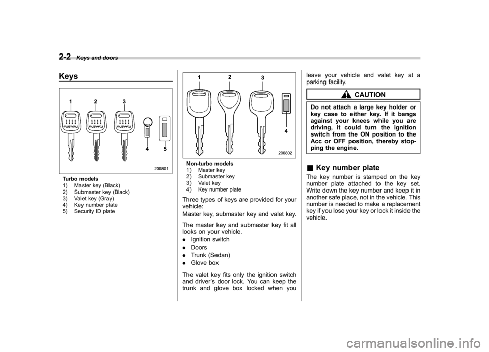
Keys
Turbo models
1) Master key (Black)
2) Submaster key (Black)
3) Valet key (Gray)
4) Key number plate
5) Security ID plate
Non-turbo models
1) Master key
2) Submaster key
3) Valet key
4) Key number plate
Three types of keys are provided for your vehicle:
Master key, submaster key and valet key.
The master key and submaster key fit all
locks on your vehicle. . Ignition switch
. Doors
. Trunk (Sedan)
. Glove box
The valet key fits only the ignition switch
and driver ’s door lock. You can keep the
trunk and glove box locked when you leave your vehicle and valet key at a
parking facility.
CAUTION
Do not attach a large key holder or
key case to either key. If it bangs
against your knees while you are
driving, it could turn the ignition
switch from the ON position to the
Acc or OFF position, thereby stop-
ping the engine.
& Key number plate
The key number is stamped on the key
number plate attached to the key set.
Write down the key number and keep it in
another safe place, not in the vehicle. This
number is needed to make a replacement
key if you lose your key or lock it inside thevehicle.
Page 86 of 364
Immobilizer (Turbo models)
The immobilizer system is designed to
prevent an unauthorized person from
starting the engine. Only keys registered
with your vehicle’s immobilizer system can
be used to operate your vehicle. Even if
an unregistered key fits into the ignition
switch and can be turned to the “START ”
position, the engine will automatically stop
after several seconds.
Each immobilizer key contains a trans-
ponder in which the key ’s ID code is
stored. When a key is inserted into the
ignition switch and turned to the “ON ”
position, the transponder transmits thekey ’s ID code to the immobilizer system ’s
receiver. If the transmitted ID code
matches the ID code registered in the
immobilizer system, the system allows the
engine to be started. Since the ID code is
transmitted and acted upon almost in-
stantly, the immobilizer system does not
impede normal starting of the engine.
If the engine fails to start, pull out the key
once before trying again. (Refer to the“ Ignition switch ”section in chapter 3.)
This device complies with Part 15 of
the FCC Rules and with RSS-210 of
Industry Canada. Operation is subject
to the following two conditions: (1) This device may not cause harmful inter-
ference, and (2) this device must
accept any interference received, in-
cluding interference that may cause
undesired operation.
Changes or modifications not ex-
pressly approved by the party respon-
sible for compliance could void theuser
’s authority to operate the equip-
ment.
NOTE
To protect your vehicle from theft,
please pay close attention to the fol-
lowing security precautions: . Never leave your vehicle unattended
with its keys inside. . Before leaving your vehicle, close all
windows and lock the doors and reargate.. Do not leave spare keys or any
record of your key number in thevehicle.
CAUTION
. Do not place the key under direct
sunlight or anywhere it may
become hot. .
Do not get the key wet. If the key
gets wet, wipe it dry with a cloth
immediately.
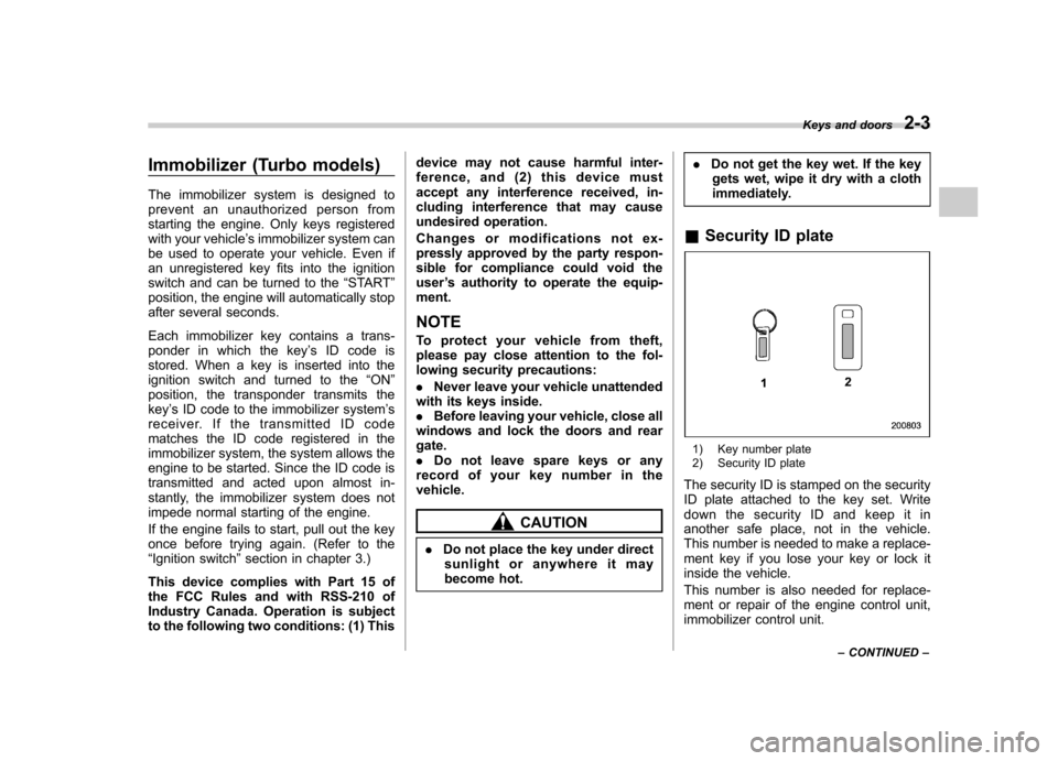
& Security ID plate
1) Key number plate
2) Security ID plate
The security ID is stamped on the security
ID plate attached to the key set. Write
down the security ID and keep it in
another safe place, not in the vehicle.
This number is needed to make a replace-
ment key if you lose your key or lock it
inside the vehicle.
This number is also needed for replace-
ment or repair of the engine control unit,
immobilizer control unit. Keys and doors
2-3
– CONTINUED –
Page 87 of 364

2-4Keys and doors
&Security indicator light
The security indicator light deters potential
thieves by indicating that the vehicle is
equipped with an immobilizer system. It
begins flashing (approximately once every
3 seconds) approximately 60 seconds
after the ignition switch is turned from the“ON ”position to the “Acc ”or “LOCK ”
position or immediately after the key is
pulled out.
If the security indicator light does not flash,
the immobilizer system may be faulty. If
this occurs, we recommend that you
contact your SUBARU dealer as soon aspossible.
In case an unauthorized key is used (e.g.
an imitation key), the security indicator
light comes on. NOTE
Even if the security indicator light
flashes irregularly or its fuse blows
(the light does not flash if its fuse is
blown), the immobilizer system will
function normally. &
Key replacement
Your key number plate and security ID
plate will be required if you ever need a
replacement key made. Any new key must
be registered for use with your vehicle ’s
immobilizer system before it can be used.
Up to four keys can be registered for use
with one vehicle.
For security, all the keys registered with
your vehicle ’s immobilizer system will
have their ID codes erased and re-
registered when a new key is made.
Therefore, all of your vehicle ’s keys must
be presented when a new key is regis-
tered. Any key that is not re-registered
when a new key is made cannot be used
after the other keys are re-registered. For
information on replacement keys and on
the registration of keys with your immo-
bilizer system, contact your SUBARU
dealer. Door locks &
Locking and unlocking from
the outside
To lock the driver ’s door from the outside
with the key, turn the key toward the rear.
To unlock the door, turn the key toward thefront.
Pull the outside door handle to open an
unlocked door.
Page 88 of 364
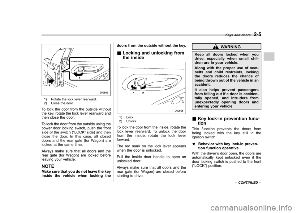
1) Rotate the lock lever rearward.
2) Close the door.
To lock the door from the outside without
the key, rotate the lock lever rearward and
then close the door.
To lock the door from the outside using the
power door locking switch, push the front
side of the switch ( “LOCK ”side) and then
close the door. In this case, all closed
doors and the rear gate (for Wagon) are
locked at the same time.
Always make sure that all doors and the
rear gate (for Wagon) are locked before
leaving your vehicle. NOTE
Make sure that you do not leave the key
inside the vehicle when locking the doors from the outside without the key.
& Locking and unlocking from
the inside
1) Lock
2) Unlock
To lock the door from the inside, rotate the
lock lever rearward. To unlock the door
from the inside, rotate the lock leverforward.
The red mark on the lock lever appears
when the door is unlocked.
Pull the inside door handle to open an
unlocked door.
Always make sure that all doors and the
rear gate (for Wagon) are closed before
starting to drive.
WARNING
Keep all doors locked when you
drive, especially when small chil-
dren are in your vehicle.
Along with the proper use of seat-
belts and child restraints, locking
the doors reduces the chance of
being thrown out of the vehicle in anaccident.
It also helps prevent passengers
from falling out if a door is acciden-
tally opened, and intruders from
unexpectedly opening doors and
entering your vehicle.
& Key lock-in prevention func- tion
This function prevents the doors from
being locked with the key still in the
ignition switch. ! Behavior with key lock-in preven-
tion function operative
With the driver ’s door open, the doors are
automatically kept unlocked even if the
door locking switch is pushed to the front( “ LOCK ”) position. Keys and doors
2-5
– CONTINUED –
Page 89 of 364

2-6Keys and doors
!Behavior with key lock-in preven-
tion function non-operative
. If the lock lever is turned to the rear
( “ LOCK ”) position with the driver ’s door
open and the driver ’s door is then closed
with the lock lever in that position, thedriver ’s door is locked.
. If the spare key is used to lock the
driver ’s door from the outside of the
vehicle, the door is locked.
This function ’s operative/non-operative
setting can be changed by a SUBARU
dealer. Contact a SUBARU dealer fordetails.
NOTE
When leaving the vehicle, make sure
you are holding the key before locking
the doors. Power door locking switches
1) Lock
2) Unlock
All doors and the rear gate (for Wagon)
can be locked and unlocked by the power
door locking switches located at thedriver ’s side and the front passenger ’s
side doors.
To lock the doors, push the front side of
the switch.
To unlock the doors, push the rear side of
the switch.
When you close the doors after you set
the door locks, the doors remain locked. NOTE
Make sure that you do not leave the key
inside the vehicle before locking the
doors from the outside using the power
door locking switches.
Page 90 of 364

Remote keyless entry system
Two transmitters are provided for your vehicle.
The remote keyless entry system has the
following functions. .Locking and unlocking the doors (and
rear gate on the Wagon) without a key. Sounding a panic alarm
. Arming and disarming the alarm sys-
tem. See the next section “Alarm system ”
for detailed information.
This device complies with Part 15 of
the FCC Rules and with RSS-210 of
Industry Canada. Operation is subject
to the following two conditions: (1) This
device may not cause harmful inter-
ference, and (2) this device must
accept any interference received, in-
cluding interference that may cause
undesired operation.
Changes or modifications not ex-
pressly approved by the party respon-
sible for compliance could void theuser ’s authority to operate the equip-
ment.
The operable distance of the keyless entry
system is approximately 30 feet (10
meters). However, this distance will vary
depending on environmental conditions. The system
’s operable distance will be
shorter in areas near a facility or electronic
equipment emitting strong radio waves
such as a power plant, broadcast station,
TV tower, or remote controller of home
electronic appliances.
The remote keyless entry system does not
operate when the key is inserted in the
ignition switch to prevent accidental lock-out.
CAUTION
. Do not expose the transmitter to
severe shocks, such as those
experienced as a result of drop-
ping or throwing.
. Do not take the transmitter apart
except when replacing the bat-
tery.
. Do not get the transmitter wet. If it
gets wet, wipe it dry with a cloth
immediately.
: LOCK/ARM button Press to Lock all doors.
Press and Hold to activate panic alarm.
Press 3 times in a 5-second period to
use vehicle finder function.
: UNLOCK/DISARM button1) Press once to Unlock driver ’s door.
2) Press a second time to Unlock all
other doors (and rear gate on the
Wagon).
& Locking the doors
Briefly press the “
”button (for less than 2
seconds) to lock all doors (and rear gate
on the Wagon).
An electronic chirp will sound once and
the turn signal lights will flash once.
If any of the doors (or the rear gate) is not Keys and doors
2-7
– CONTINUED –